

K-WANG
+086-15305925923
Service expert in industrial control field!


Product
Article
NameDescriptionContent
Adequate Inventory, Timely Service
pursuit of excellence


Ship control system
Equipment control system
Power monitoring system
Brand
Product parameters
- Telephone:+86-15305925923
- contacts:Mr.Wang
- Email:wang@kongjiangauto.com
Description
Discrete output modules IC200MDL741 and BXIOODP1624 provide
one group of 16 discrete outputs.
GE IC200MDL741 ESCPOutput Module
Discrete output modules IC200MDL742 and BXIOODP3224, shown
below, provides two groups of 16 discrete outputs.
Each point has electronic overcurrent protection and short circuit
protection, and generates a fault if either condition exists. The outputs
are positive or sourcing type outputs. They switch the loads to the
positive side of the DC supply and thus supply current to the loads.
OUTPUT 24VDC
POS LOG ESCP .5A 32PT
FLD
OK PWR
1 2 3 4 5 6 7 8 9 10 11 12 13 14 15 16
Q
Q
17 18 19 20 21 22 23 24 25 26 27 28 29 30 31 32
FLD OK PWR
An external DC power supply must be provided to switch power to the
loads.
Intelligent processing for this module is performed by the CPU or NIU.
LED Indicators
Individual green LEDs indicate the on/off state of the output points. The
LEDs are dependent on field power, but independent of load conditions.
Individual amber LEDs indicate overload conditions on each output.
The green FLD PWR LED is on when field power is applied to the
module.
The green OK LED is on when backplane power is present to the
module.
Diagnostics
The module reports the presence of any overloaded points to the
system on a per-module basis. Amber LEDs indicate the overload
conditions on a per-point basis. Once the overload condition is
removed, normal operation is resumed.
Preinstallation Check
Carefully inspect all shipping containers for damage. If any equipment
is damaged, notify the delivery service immediately. Save the damaged
shipping container for inspection by the delivery service. After
unpacking the equipment, record all serial numbers. Save the shipping
containers and packing material in case it is necessary to transport or
ship any part of the system.
External Power Supply Requirements
The external power supply used to power the loads must provide
sufficient field power for the module during short circuit events. When a
load is shorted, an inadequate external power supply may allow field
power to drop below the specified operating range, causing
misoperation of the module. The external power supply must be
capable of providing short circuit energy without degradation of output
voltage levels. The amount of energy required depends on the number
of simultaneously-shorted points that might occur. Refer to power
supply short circuit operation specifications when selecting the power
supply to be used with the loads.
Local energy storage (either batteries or capacitors) can be used to
compensate for insufficient power supply characteristics. Additional
best practices including minimizing wiring resistance from the external
power supply to the module must be observed.
Module Characteristics
Points IC200MDL741, BXIOODP1624: 1 group of 16 outputs
IC200MDL742, BXIOODP3224: 2 groups of 16 outputs
Module ID IC200MDL741, BXIOODP1624: FFFF8080
IC200MDL742, BXIOODP3224: 80808080
User input to logic (optical) and frame ground: 250VAC
continuous; 1500VAC for 1 minute
IC200MDL741, BXIOODP1624: Group to group: not
applicable
IC200MDL742, BXIOODP3224: Group to group: 250VAC
continuous; 1500VAC for 1 minute
Isolation:
Point to point: none
LED indicators One green LED per point shows individual point on/off
state
One amber LED per point shows individual point
overloads
FLD PWR LED indicates field power is present
OK LED indicates backplane power is present
Backplane current
consumption
IC200MDL741, BXIOODP1624: 5V output: 75mA
maximum
IC200MDL742, BXIOODP3224: 5V output: 150mA
maximum
External power supply +18 to +30VDC, +24VDC nominal
Thermal derating See diagrams
Output Characteristics
Output voltage +18 to +30VDC, +24VDC nominal
Output voltage drop 0.5V maximum
Load current 0.5A at 30VDC maximum (resistive)
2.0A inrush maximum for 100ms
Steady-state
overcurrent trip point
1.6A typ., 0.7A to 2.5A max range
Output leakage
current
0.5mA at 30VDC maximum
On and Off response
time
0.5ms, maximum
Protection (each
output)
Short circuit and overcurrent protection, free-wheeling
diodes
Product Revision History
Rev Date Description
IC200MDL741F
BXIOODP1624F
IC200MDL742E
BXIOODP3224E
October 2008 Updated Power Supply OK signal
circuitry.
IC200MDL741E
BXIOODP1624E
IC200MDL742D
BXIOODP3224D
April 2005 Improvement to latching mechanism
IC200MDL741D
IC200MDL742C
April 2004 Changed to V0 plastic for module
housing.
IC200MDL741C
IC200MDL742B
January 2004 ATEX approval for Group 2 Category
3 applications.
BXIOODP1624D
BXIOODP3224C
January 2004 Changed to V0 plastic for module
housing. ATEX approval for Group 2
Category 3 applications.
IC200MDL741A
BXIOODP1624A
IC200MDL742A
BXIOODP3224A
December 1998 Initial product release.
Installation in Hazardous Locations
• EQUIPMENT LABELED WITH REFERENCE TO CLASS I,
GROUPS A, B, C & D, DIV. 2 HAZARDOUS LOCATIONS IS
SUITABLE FOR USE IN CLASS I, DIVISION 2, GROUPS A, B,
C, D OR NON-HAZARDOUS LOCATIONS ONLY
• WARNING - EXPLOSION HAZARD - SUBSTITUTION OF
COMPONENTS MAY IMPAIR SUITABILITY FOR CLASS I,
DIVISION 2;
• WARNING - EXPLOSION HAZARD - WHEN IN HAZARDOUS
LOCATIONS, TURN OFF POWER BEFORE REPLACING OR
WIRING MODULES; AND
• WARNING - EXPLOSION HAZARD - DO NOT DISCONNECT
EQUIPMENT UNLESS POWER HAS BEEN SWITCHED OFF
OR THE AREA IS KNOWN TO BE NONHAZARDOUS.
Field Wiring Terminals
Terminal Connection Terminal Connection
A1 Output 1 B1 Output 17 *
A2 Output 2 B2 Output 18 *
A3 Output 3 B3 Output 19 *
A4 Output 4 B4 Output 20 *
A5 Output 5 B5 Output 21 *
A6 Output 6 B6 Output 22 *
A7 Output 7 B7 Output 23 *
A8 Output 8 B8 Output 24 *
A9 Output 9 B9 Output 25 *
A10 Output 10 B10 Output 26 *
A11 Output 11 B11 Output 27 *
A12 Output 12 B12 Output 28 *
A13 Output 13 B13 Output 29 *
A14 Output 14 B14 Output 30 *
A15 Output 15 B15 Output 31 *
A16 Output 16 B16 Output 32 *
A17 DC - B17 DC - *
A18 DC + B18 DC + *
* Inputs for 32-point modules only.
Each group of 16 outputs has a DC+ and a DC- terminal.
When wiring outputs to inductive loads, use of external suppression
circuits is recommended. See chapter 2, “Installing Wiring for I/O
Devices-Wiring to Inductive Loads” in the VersaMax I/O System
Manual, GFK-1504, for more information.
For modules IC200MDL741 and BXIOODP1624, if additional bussed
terminals are needed, the B terminals can be made available by using
a shorting bar. The shorting bar has a maximum current-carrying
capacity of 2A per point. See chapter 2 of the VersaMax I/O System
Manual, for additional information about the shorting bar.
Wiring Connections for Carriers with Two Rows of Terminals
Row B connections are for 32-point modules only.
Q1 Q2 Q3 Q4 Q5 Q6 Q7 Q8 Q9 Q10 Q11 Q12 Q13 Q14 Q15 Q16
Q28 Q29 Q30 Q32 Q1 Q1 Q1 Q2 Q2 Q2 Q2 Q2 Q2 Q2 Q2 Q3
1 2 3 4 5 6 7 8 9 11 12 13 14 15 16 17 18
1 2 3 4 5 6 7 8 9 11 12 13 14 15 16 17 18 10
10
B
A
Wiring Connections for Carriers with Three Rows of Terminals
Side B connections are for 32-point modules only.
1 2 3 4 5 6
13 14 15 16 17 18
7 8 9 11 12 10
B
+ -
Q1 Q1 Q1 Q2 Q2 Q2
Q28 Q2 Q2 Q2 Q2 Q2
Q29 Q30 Q32 Q3
A 1 2 3 4 5 6
13 14 15 16 17 18
7 8 9 11 12 10
Q1 Q3
Q7
Q15
Q5
Q9 Q11
Q13
Q2 Q4
Q8
Q16
Q6
Q10 Q12
Q14
Operating Note
If hot insertion of a module is done improperly, the operation of other
modules on the same backplane may be disrupted. See Installing a
Module on a Carrier in the VersaMax Modules Manual, GFK-1504.
Thermal Derating
The number of points that can be on at the same time depends on the
ambient temperature, the external voltage, and the orientation of the
module and DIN rail. The charts below show example thermal deratings
for the module at 24VDC and 30VDC with the maximum output current
per point.
Purchase history
| User name | Member Level | Quantity | Specification | Purchase Date |
|---|
Total 0 Record
Customer Reviews
Satisfaction :
5 Stars
No evaluation information


-
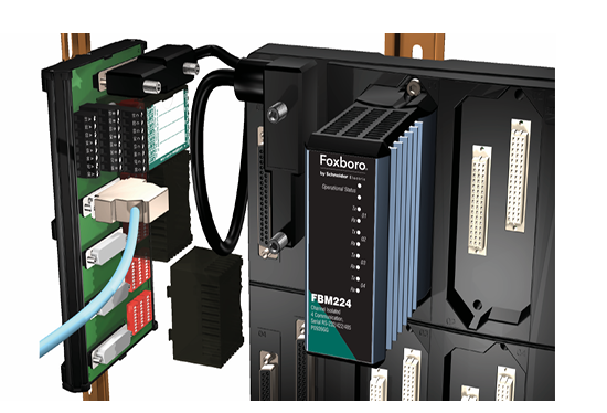 Foxboro FBM224 Modbus ® communication module
 -
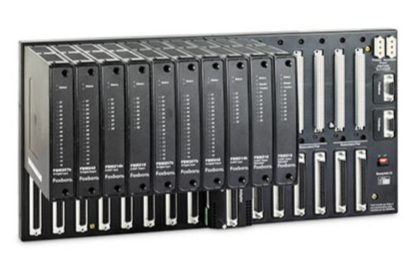 Foxboro Evo ™ Compact 200 Series I/O Subsystem
 -
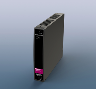 Foxboro ™ DCS Compact FBM201 Analog Input Interface Module
 -
 SIEMENS SGT-2000E series gas turbine
 -
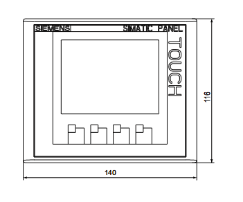
 SIEMENS SIMATIC HMI Intelligent Panel
 -
 SIEMENS SIMATIC HMI Intelligent Panel Operation Instructions
 -
 SIEMENS SIMATIC S7 300/400 operates MICROMASTER 4 (MM4) frequency converter through Profibus DP
 -
 SIEMENS SIMATIC HMI Basic Panels Operating Manual
 -
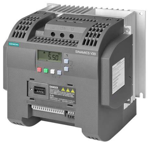
 SIEMENS SINAMICS G120 Control Unit CU240E
 -
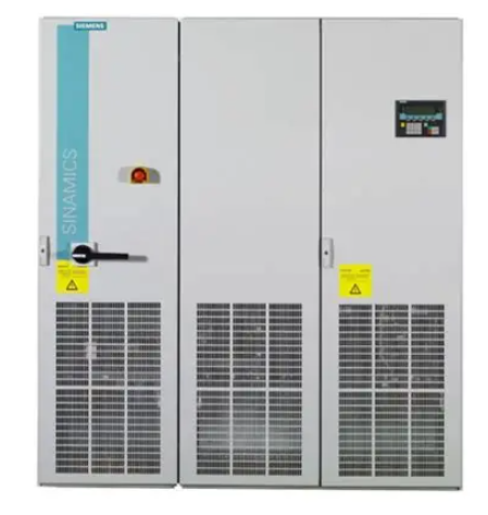 SIEMENS SINAMICS G130/G150 products
 -
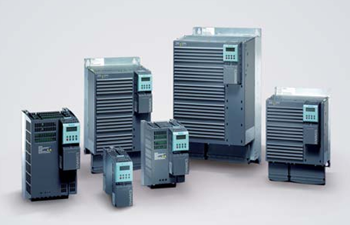
 SIEMENS SINAMICS Low Voltage Inverter
 -
 SIEMENS Climatix ™ S400 STD HVAC Controller (POS646 Series)
 -
 SIEMENS 3AH3 vacuum circuit breaker
 -
 SIEMENS QFM31xx series air duct sensor
 -
 SIEMENS SIMOTICS SD 1LE7 series low-voltage motor (shaft height 71-315)
 -
 SIEMENS SIMOTICS L-1FN3 series linear motor
 -
 SIEMENS SITRANS P DS III series pressure transmitter
 -
 SIEMENS ICROMASTER 420 frequency converter
 -
 SIEMENS SIMOGEAR Gear Motor Products
 -
 SIEMENS 40.5kV 3AE8 Solid Sealed Series Vacuum Circuit Breaker
 -
 SIEMENS PL and ES Series Load Centers Selection and Application Guide
 -
 SIEMENS SIMATIC Drive Controller System
 -
 SIEMENS SIMATIC S7-1500/ET 200MP Automation System
 -
 SINAMICS SIRIUS series switchgear
 -
 SIEMENS G120 CU240BE-2 frequency converter
 -
 SIEMENS 3AH3 series vacuum circuit breaker
 -
 SIEMENS 1PH7 series asynchronous motors for machine tools
 -
 SIEMENS SIMOTICS 1LE8 series low-voltage high-power motor
 -
 SIEMENS SIMATIC S5 series PLC STEP 5 programming software
 -
 SIEMENS E50 series terminal power distribution products
 -
 SIEMENS SIMOTICS SD 1LE5 series low-voltage motor
 -
 SIEMENS SIMOTICS L-1FN3 Linear Motor Operating Instructions
 -
 SIEMENS VVF53./VXF53. series flange valves
 -
 SIEMENS SIMATIC S5 S5-115U Programmable Controller
 -
 SIEMENS SMART S7-200 Intelligent Programmable Controller
 -
 SIEMIENS MCCB Series Short Circuit Rating Guide
 -
 SIEMIENS SIPART PS2 (6DR5...) Electrical Positioner Operation Guide
 -
 SIEMIENS SIMATIC TP170B Touch Screen
 -
 SIEMENS SIMATIC TI545/TI555 Controller
 -
 SIEMIENS SIMATIC 505 Analog I/O Module
 -
 SIEMIENS S7-1200/1500 Controller TIA Portal Programming Guide
 -
 SIEMIENS PFT6 series weighing sensor
 -
 SIEMIENS 1FK6 series three-phase servo motor
 -
 Siemens medium voltage vacuum switch technology and components
 -
 TEKTRONIX CFG 253 Function Generator
 -
 TEKTRONIX P6022 Current Probe
 -
 Tektronix AWG70000 series arbitrary waveform generator
 -
 Tektronix AWG2021 250 MHz Arbitrary Waveform Generator
 -
 Tektronix DMM4050 6 half bit high-precision digital multimeter
 -
 Tektronix 370B Programmable Curve Tracer
 -
 TEKTRONIX TCPA300/400 current probe amplifier
 -
 Tektronix AFG1022 Function Generator
 -
 Tektronix P6139A 10X Passive Probe
 -
 Tektronix 3 Series Hybrid Domain Oscilloscope
 -
 TEKTRONIX AFG31000 series arbitrary function generator
 -
 TEKTRONIX THDP0100/0200 and TMDP0200 series high-voltage differential probes
 -
 TEKTRONIX 3 Series Mixed Domain Oscilloscope MDO32 and MDO34
 -
 Tektronix 2440 digital oscilloscope
 -
 Tektronix MSO4000/DPO4000 series digital fluorescence oscilloscope
 -
 Tektronix TPS2000 series digital storage oscilloscope
 -
 Tektronix TBS1000B and TBS1000B-EDU series digital storage oscilloscopes
 -
 Tektronix XYZs of Oscilloscopes
 -
 TEKTRONIX 4K/UHD Monitoring and Measurement Guidelines
 -
 Tektronix 5 Series Mixed Signal Oscilloscope (MSO54/56/58)
 -
 Tektronix TDS3000 series digital fluorescence oscilloscope
 -
 TEKTRONIX MSO5000B, DPO5000B series mixed signal oscilloscope
 -
 Tektronix TBS1000 series digital storage oscilloscope
 -
 Tektronix 4000 series oscilloscope
 -
 TEKTRONIX VX4240 VXIbus protocol waveform digitizer/analyzer module
 -
 GE PACSystems RSTi EP EPSCPE100 Programmable Controller
 -
 TEKTRONIX 5B12N Dual Time Base Plugin
 -
 TEKTRONIX 5A22N Differential Amplifier
 -
 Tektronix 5440 oscilloscope
 -
 TOSHIBA MULTIFUNCTIONAL DIGITAL SYSTEMS TopAccess Guide
 -
 TOSHIBA e-STUDIO 7516AC Color Multifunctional Printer
 -
 TOSHIBA e-STUDIO 7516AC Series Color Multifunctional Printer
 -
 TOSHIBA CANVIO BASICS portable hard drive
 -
 TOSHIBA TOSBERT TM VF-nC1 Industrial Inverter
 -
 TOSHIBA TE2 series low-voltage digital solid-state soft starter
 -
 ABB Sace BSD series brushless servo drive
 -
 TOSHIBA VF-S15 frequency converter
 -
 TOSHIBA Color TV User Manual
 -
 TOSHIBA 2505AC, 3005AC, 3505AC mid to high end commercial grade multifunctional composite machine
 -
 TOSHIBA External and Internal Hard Drives
 -
 TOSHIBA 1600XPi Series UPS Installation and Operation
 -
 TOSHIBA TOSBERT S11 series frequency converter
 -
 Toshiba TOSBERT S7 series frequency converter
 -
 Toshiba Motor's Low Voltage Product Series
 -
 TOSHIBA VF-AS3 inverter RS485 communication function
 -
 TOSHIBA TOSBERT VF-A3 frequency converter
 -
 TOSHIBA V200 series programmable logic controller
 -
 TOSHIBA TOSBERT VF-S15 series frequency converter
 -
 TRICON ®/ Installation and maintenance of E/E2/E3 transmitters
 -
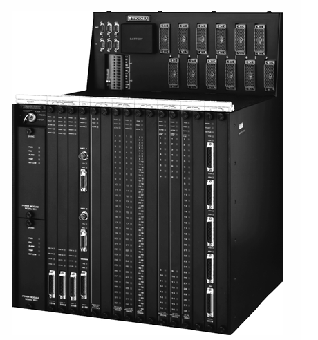 TRLC0NEX Tricon fault-tolerant controller
 -
 WAGO 221 series LEVER-NUTS ® Compact splicing connector
 -
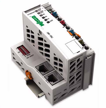 WAGO-I/O-SYSTEM 750 Programmable Fieldbus Controller ETHERNET
 -
 WAGO Rail-Mount Terminal Blocks with Screw and Stud Connection
 -
 WAGO series molded case circuit breaker (MCCB)
 -
 WAGO Rail-Mount Terminal Blocks
 -
 WAGO I/O System 750/753 Series Distributed Automation System
 -
 HIMA X-CPU 01 processor module
 -
 Westinghouse iGen5000 Digital Inverter Generator
 -
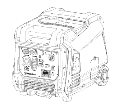
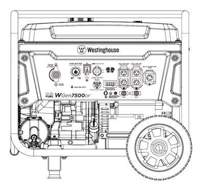 Westinghouse WGen7500DF Dual Fuel Portable Generator
 -
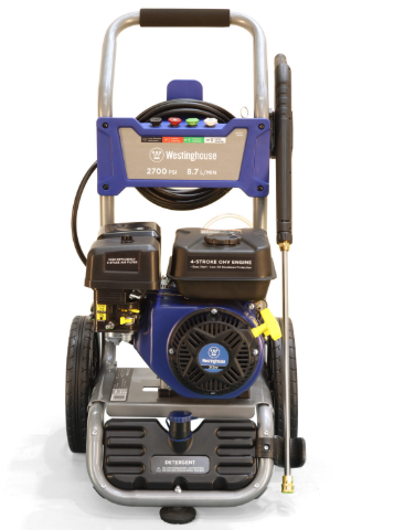 Westinghouse WPX2700H/WPX3100H High Pressure Cleaning Machine
 -
 Westinghouse WH7500V portable generator
 -
 Westinghouse WGen9500c portable generator
 -
 Westinghouse DS/DSL series low-voltage power circuit breakers
 -
 Westinghouse ePX3500 Electric High Voltage Cleaning Machine
 -
 Westinghouse ST Switch Intelligent Automatic Portable Transfer Switch
 -
 Westinghouse 2400i digital inverter generator
 -
 Westinghouse iGen series digital inverter generator
 -
 HIMA CPU 01 Controller Module
 -
 Westinghouse WPX3000e/WPX3400e electric high-pressure cleaning machine
 -
 Westinghouse WGen2000, WGen3600, and WGen3600V portable generators
 -
 Westinghouse WGen5500 Generator
 -
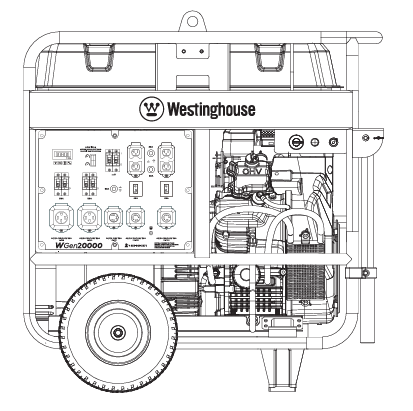 Westinghouse WGen20000 Generator
 -
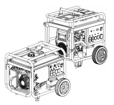 Westinghouse WPro8500 and WPro12000 portable generators
 -
 Westinghouse iGen4500DFc Dual Fuel Digital Variable Frequency Generator
 -
 Watlow Series L Temperature Limiting Controller
 -
 Watlow Series F4P Series 1/4 DIN (96 × 96mm) Temperature/Process Controller
 -
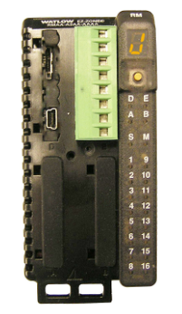
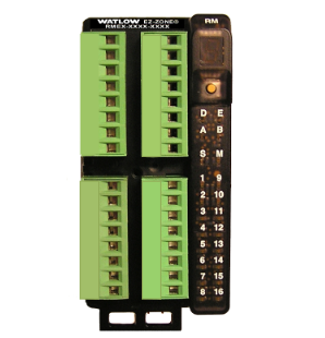 Watlow EZ-ZONE ® RME (Expansion) Module
 -
 Watlow EZ-ZONE ® RMA (Access) module
 -
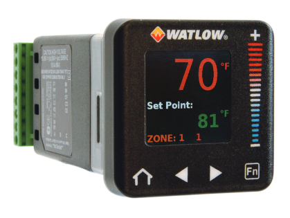 Watlow PM PLUS ™ 6 Series PID Integrated Controller
 -
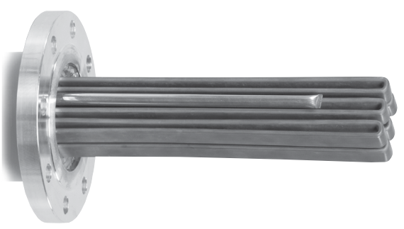 Watlow Immersion Heater
 -
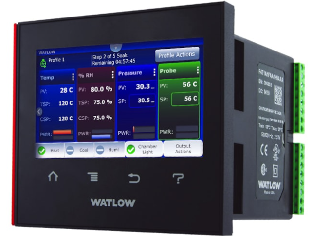 Watlow F4T Controller Installation and Failure
 -
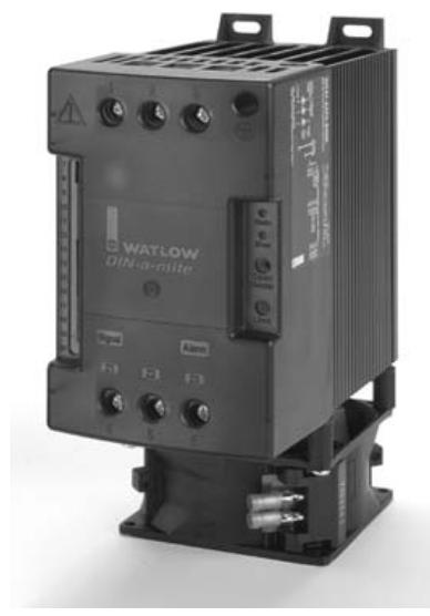 Watlow DIN-A-MITE ® Style C Solid State Power Controller
 -
 Watlow plug-in heater
 -
 Watlow Series 942 Controller

