
K-WANG


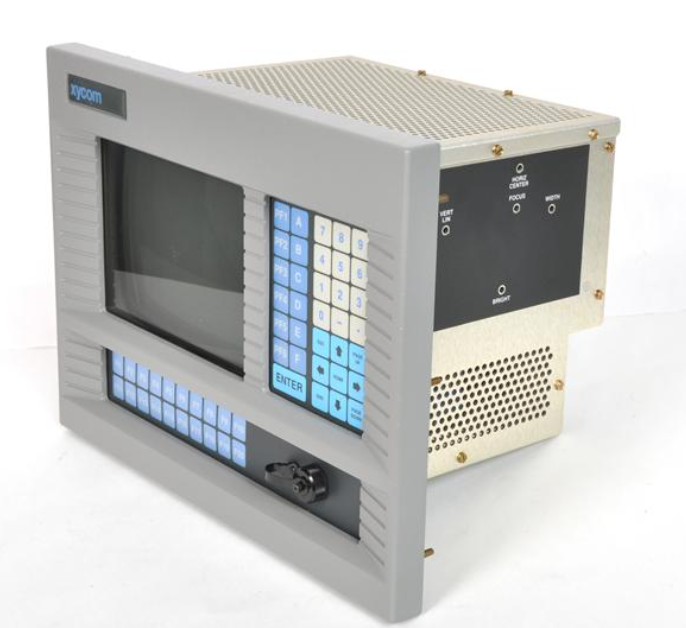
PRO-FACE XYCOM 1546 Heavy Industrial PC 1546-1120310130001
These node box industrial PCs feature an open architecture to meet a wide variety of applications that require both a powerful PC and a durable industrial enclosure.
The systems integrate a computer card cage, mass storage, and power supply in a truly industrial form.
The processor board combines all the functions of a complete PC/AT® compatible computer on a single industrially hardened circuit board.
The 1546 and 1547 Node Box Industrial PCs offer a powerful, compact package for the factory floor and other harsh environments.
These node box industrial PCs feature an open architecture to meet a wide variety of applications that require both a powerful PC and a durable industrial enclosure.
The systems integrate a computer card cage, mass storage, and power supply in a truly industrial form.
Standard Features
Parallel port
A, B, C, D, F, and G
Optional Features
Unpacking the System
When you remove the system from its shipping container, verify that you have the parts listed below.
Save the box and inner wrapping in the event you need to reship the unit.
Mounting hardware
The rugged design of the 1546 and 1547 Node Boxes allows it to be installed in most industrial environments.
The system is generally placed in a NEMA 4/4X/12 enclosure to protect against contaminants such as dust, and moisture.
Metal enclosures also help minimize the effects of electromagnetic radiation that nearby equipment can generate.
For Underwriters Laboratories (UL) compliance, the unit must be installed within a suitable fire enclosure.
Place any fans or blowers close to the heat generating devices.
If using a fan, make sure that outside air is not brought into the enclosure unless a fabric or other reliable filter is used.
This filtration prevents conductive particles and other harmful contaminants from entering the enclosure.
Do not select a location near equipment that generates excessive electromagnetic interference (EMI) or radio frequency interface (RFI).
Examples of these types of equipment are: high power welding machines; induction heating equipment;and large motor starters.
system.
The proper location of incoming line devices keeps power wire runs as short as possible and minimizes electrical noise transmitted to the unit.
Avoid circuit overloading of the supply circuit
System Power
Proper grounding is essential to all safe electrical installations.
Refer to the relevant Federal, State/Provincial, and local electric codes, which provide data
such as the size and types of conductors, color codes and connections necessary for safe grounding of electrical components.
The code specifies that a grounding path must be permanent (no solder), continuous, and able to safely conduct the ground-fault current in the system with minimal impedance (minimum wire required is #18 AWG, 1 mm).
Separate ground wires (P.E. or Protective Earth) from power wires at the point of entry to the enclosure.
To minimize the ground wire length within the enclosure,locate the ground reference point near the point of entry for the plant power supply.
All electrical racks or chassis and machine elements should be Earth Grounded in installations where high levels of electrical noise can be expected.
The rack/chassis should be grounded with a ground rod or attached to nearby Earth structure such as a steel support beam.
Each different apparatus should be connected to a single Earth Ground point in a “star” configuration with low impedance cable.
Scrape away paint and other nonconductive material from the area where a chassis makes contact with the enclosure.
- YOKOGAWA
- Reliance
- ADVANCED
- SEW
- ProSoft
- WATLOW
- Kongsberg
- FANUC
- VSD
- DCS
- PLC
- man-machine
- Covid-19
- Energy and Gender
- Energy Access
- Renewable Integration
- Energy Subsidies
- Energy and Water
- Net zero emission
- Energy Security
- Critical Minerals
- A-B
- petroleum
- Mine scale
- Sewage treatment
- cement
- architecture
- Industrial information
- New energy
- Automobile market
- electricity
- Construction site
- HIMA
- ABB
- Rockwell
- Schneider Modicon
- Siemens
- xYCOM
- Yaskawa
- Woodward
- BOSCH Rexroth
- MOOG
- General Electric
- American NI
- Rolls-Royce
- CTI
- Honeywell
- EMERSON
- MAN
- GE
- TRICONEX
- Control Wave
- ALSTOM
- AMAT
- STUDER
- KONGSBERG
- MOTOROLA
- DANAHER MOTION
- Bentley
- Galil
- EATON
- MOLEX
- Triconex
- DEIF
- B&W
- ZYGO
- Aerotech
- DANFOSS
- KOLLMORGEN
- Beijer
- Endress+Hauser
- schneider
- Foxboro
- KB
- REXROTH
- YAMAHA
- Johnson
- Westinghouse
- WAGO
- TOSHIBA
- TEKTRONIX
- BENDER
- BMCM
- SMC
- HITACHI
- HIRSCHMANN
- XP POWER
- Baldor
- Meggitt
- SHINKAWA
- Other Brands
- UniOP
- KUKA
- IBA
- Beckhoff
- ADLINK
-
Beckhoff CX5020-0112 - PLC Module
-
Beckhoff CP2912-0000 - Control Panel
-
Beckhoff C6920-1047-0030 - industrial control cabinet control PC
-
BECKHOFF CX1020-0121 - CPU Module Power Supply Setup
-
Beckhoff EL6752 - DeviceNet Master EtherCAT Terminal
-
Beckhoff IP1002-B518 - Fieldbus Box Module
-
Beckhoff CP6606-0001-0020 - 7 inch Economy Panel PC incl. Connection Cable
-
Beckhoff CX5010-0111 - Controller Module
-
BECKHOFF AX2020-S62000-520 - SERVO DRIVE 5.76
-
Beckhoff EL1904 - 4-Channel Digital Input Module
-
BECKHOFF AX5201-0000 - Servo Drive
-
Beckhoff CP7201-1000-0000 - Industrial PC with Touch Screen
-
Beckhoff BK7350 - module Bus Coupler
-
BECKHOFF C6930-0010 - PLC PC Industrial PC
-
Beckhoff AX5125-0000 - Servo Amplifier
-
Beckhoff CX2100-0914 - Power Supply for External UPS for CX20xx
-
Beckhoff CP6608-1000-0010 - Control Panel
-
Beckhoff EL7221-9014 - EtherCAT Terminal, 1 Channel Motion Interface, 48 V DC
-
BECKHOFF CP2919-0000 - Multitouch Built-In Control Panel 24VDC 19"
-
BECKHOFF C6015-0010 - TWINCAT2 Single Core 1.46GHz Industrial PC
-
Beckhoff CU8803-0000 - Controller Module Transmitter
-
BECKHOFF CU1521-0000 - EtherCAT media converter
-
Beckhoff CX5140-0111 - Control Embedded PC HW 3.1 + Flash Card CX2900-0028 4GB
-
Beckhoff AX2513-B200 - Servo Amplifier Servodrive
-
Rexroth MSK061C-0600-NN-M1-UP1-NNNN - Engine Servo Motor
-
Beckhoff AM3031-0C01-0000 - Servo Motor
-
BECKHOFF CP7201-1000-0000 - Industrial PC with touch screen
-
BECKHOFF C6925-0000 - PLC Module Industrial PC
-
BECKHOFF EL5151-0021 - PLC module Encoder Interface
-
Beckhoff CX5130-0125-1001 - Module Embedded PC
-
BECKHOFF EP3356-0022 - EtherCAT Box Module
-
BECKHOFF AX5203-0000 - SERVO DRIVE
-
B&R X20IF1082 - COMMUNICATION INTERFACE MODULE POWER LINK
-
BECKHOFF EL7342 - PLC Module 2-Channel DC Motor Output
-
BECKHOFF CX8190 - Ethernet Controller
-
BECKHOFF CX2020-0120/4GB - CPU CX2100-0904 3x EL6900 EL1904 16GB RAM
-
Beckhoff CX5130-0112 - Module Embedded PC
-
Beckhoff CP7701-0001-0020 - Panel-PC Touch Panel 12" ELO Accutouch AMD ALX 500MHz
-
BECKHOFF CX5020-0111 - Embedded PC Controller
-
Beckhoff CX2040-0100 - Embedded PC HW: 4.0 + CX2100 0014 + 4GB CFast Card
-
Beckhoff CP6512-0001 0030 - Control Panel
-
beckhoff CX9020-0111-0900 - Controller Modules
-
Beckhoff IE3112 - Module Fieldbus Box
-
BECKHOFF CX8051 - PLC Module
-
BECKHOFF CX1100-0920 - module Power Supply
-
Beckhoff CP7921-1075-0000 - Control Panel
-
B&R 3NC352.6 - PLC Module
-
Beckhoff CX8095 - module Controller
-
beckhoff CX1020-0021 - CPU controller module
-
BECKHOFF BK9103 - PROFINET BUS COUPLER
-
Beckhoff C6930-0050 - Schaltschrank-Industrie-Pc Core i7-4700 CPU+FC9062 Modules
-
Beckhoff AM8013-0DH0-1001 - Servo Motor
-
BECKHOFF EPP3184-0002 - Module EtherCAT-P Box
-
BECKHOFF AM8041-0H10-0000 - servo motor
-
BECKHOFF CX1010-0100 - Embedded PC Module System
-
beckhoff CP2916-0000 - Industrial touch screen
-
Beckhoff C6110 - Industrial PC Boser HS6237
-
Beckhoff CX1010-0111 - CPU Module Setup
-
Beckhoff EL3751 - EtherCAT Terminal 1 Channel Analog Input Multifunction 24 Bit
-
BECKHOFF AX5721-0000 - Encoder Interface Card
-
Beckhoff CX1020-0122 - module Embedded PC
-
BECKHOFF CP3921-0000 - Control Panel
-
BECKHOFF CX2040-0155 - STANDARD CPU MODULE INTEL I7 2715QE 2.1GHz
-
BECKHOFF CX5020-0111 - Controller module
-
Beckhoff AX5201-0000-0200 - servo drive
-
BECKHOFF CP2921-0000 - Multi-touch built-in Control Panel with DVI/USB
-
BECKHOFF CP3907-0000 - Touch Panel
-
Beckhoff CX5120-0115 - CPU Module
-
Beckhoff KL3361 - PLC Module Oscilloscope Terminal
-
Beckhoff CX1000-0111 - Embedded PC System Combination
-
Beckhoff AM8023-0E20-0000 - Servo motor with Tramec EP75/2 Transmission
-
beckhoff am8533-2f10-0000 - servo motor
-
BECKHOFF EL5042 - EtherCAT Terminal
-
Beckhoff CX9001-1001 - PLC Module
-
BECKHOFF CX9020-0112 - Digital Module CPU Controller
-
BECKHOFF CP6709-0001-0000 - Touchpanel
-
Beckhoff 1004B2060000 - Communication Module
-
Beckhoff CX5020-0112 - PLC Controller
-
BECKHOFF EL2904 - EtherCAT Safety Input Output Module 24V
-
Beckhoff CX2040-0142 - Embedded PC Controller Module
-
BECKHOFF AM8121-0F20-0000 - SERVO MOTOR
-
Beckhoff CX9020-0112 - CPU Module
-
BECKHOFF CB3050-0008 - PCB Motherboard Board
-
Beckhoff EK1512-0010 - PLC Module EtherCAT Junction
-
BECKHOFF CX1001-0121 - Embedded PC And CPU Basic Module Controller
-
Beckhoff C6032-0070 - Industrial PC
-
Beckhoff CX1020-0122 - Module Embedded PC
-
BECKHOFF CX8010 - Controller Module
-
BECKHOFF EK1818 - Modules EtherCAT Bus Coupler
-
BECKHOFF CX5140-0155 - PLC Embedded PC
-
BECKHOFF CX1100-0910 - Power Supply Module
-
Beckhoff CX1001-0121 - CPU Module + CX1000-C00L + CX1100-0002 + CX1000-N001
-
Beckhoff CP6801-0001-0010 - Control Panel
-
BECKHOFF BK9103-1005 - Bus Coupler PROFINET
-
Beckhoff AX5203-0000-0202 - 161336 Digital Compact Servo Amplifier 2 Channel
-
BECKHOFF CX5020-0111 - Controller module
-
BECKHOFF CP7032-1031-0010 - Cp-Link Control Panel
-
Beckhoff AX5112-0000-0200 - Servo Driver
-
Beckhoff BX8000-0000 - RS232/RS485 Bus Terminal Controller | HW:1.4
-
BECKHOFF CX2020-0120 - CPU MODULE WITH CX2100 Power Supply
-
Beckhoff EL4012 - Module EtherCAT Terminal
-
BECKHOFF CP6204-0001-0030 - ECONOMY INSTALLATION CONTROL PANEL
-
Beckhoff CP6833-0001-0011 - Built-In Control Panel-Without Control Panel Monitor
-
BECKHOFF EK1521-0000 - module EtherCAT junction
-
Beckhoff EP3314-0002 - EtherCAT Compact Box M12 4x Analog Input Thermoelements
-
Beckhoff CX8090 - PLC modules Controller
-
Beckhoff AM8033-0JG0-0000 - Servo Motor
-
Beckhoff CP9035.2 - CP9035 capture card
-
Beckhoff CP7802-1241-0010 - Industrial Touchscreen 15 Inch
-
Beckhoff BX8000-0000 - Module Bus Terminal Controller
-
BECKHOFF IE1002-0000 - Junction box
-
Beckhoff AM237S-0021 - Servomotor
-
Beckhoff EL2564 - EtherCAT Terminal, 4-channel LED output, 5-48VDC, 4A, RGBW
-
BECKHOFF EL1918 - EtherCAT Terminal 8-Channel Digital Input 24V DC
-
Beckhoff CB3052-0005 - Circuitboard Motherboard
-
Beckhoff AM8023-2E11-0000 - Servomotor
-
Beckhoff CX8190 - Ethernet Controller
-
BECKHOFF EL4038 - Module EtherCAT Terminal
-
B&R 5PC910.SX01-00 - APC910 Industrial PC | i5-6440EQ 8GB
-
Beckhoff CP9030-A002 - CP-Link Karte Version: 1.1
-
BECKHOFF BK7200 - CTNET Control Techniques Bus Coupler
-
Beckhoff CP2616-0000 - Multi-Touch Touchscreen Panel for 24V DC Automation
-
BECKHOFF LOT 31 modules - PLC Module Bundle
-
BECKHOFF EJ2889-0000 - Module EtherCAT Plug-in Module
-
BECKHOFF AM8043-0H20-0000 - Servomotor
-
BECKHOFF EL3154 - module EtherCAT Terminal
-
Beckhoff C6017-0030 - Industrial PC
-
BECKHOFF CX9020-0112 - CPU Module

K-JIANG

Add: Jimei North Road, Jimei District, Xiamen, Fujian, China
Tell:+86-15305925923