
K-WANG
+086-15305925923
Service expert in industrial control field!


Product
Article
NameDescriptionContent
Adequate Inventory, Timely Service
pursuit of excellence


Ship control system
Equipment control system
Power monitoring system
Current position:
新闻动态
newS
Brand
BENTLY 1900/65A General Purpose Equipment Monitor
The 1900/65A General Purpose Equipment Monitor is designed to continuously monitor and protect equipment that is used in a variety of applications and industries. The monitor’s low cost makes it an ideal solution for general purpose machines and processes that can benefit from continuous monitoring and protection.
BENTLY 1900/65A General Purpose Equipment Monitor
Description
The 1900/65A General Purpose Equipment Monitor is designed to continuously monitor and protect equipment that is used in a variety of applications and industries. The monitor’s low cost makes it an ideal solution for general purpose machines and processes that can benefit from continuous monitoring and protection.
Inputs
The 1900/65A provides four transducer inputs and four temperature inputs. Software can configure each transducer input to support 2- and 3-wire accelerometers, velocity sensors or proximity sensors. Each temperature input supports Type E, J, K, and T thermocouples, and 2- or 3-wire RTDs.
Outputs
The 1900/65A provides six relay outputs, four 4-20 mA recorder outputs, and a dedicated buffered output. The user can use the 1900 Configuration software to configure the relay contacts to open or close according to the OK, Alert and
Danger statuses of any channel or combination of channels, and to provide data from any variable from any channel on any recorder output. The dedicated buffer output can provide the signal for each transducer input.
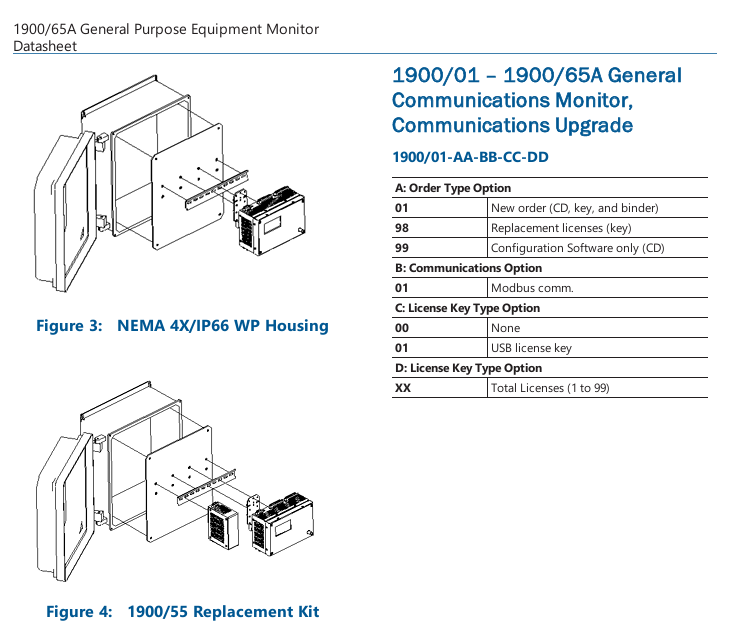
A Modbus Gateway option allows the monitor to provide static variables, statuses, event list, time and date information directly to any Modbus client, including Distributed Control Systems (DCSs), Supervisory Control and Data Acquisition (SCADA) systems, Programmable Logic Controllers (PLCs), or System 1 software. The monitor uses an internal counter and a Modbus client/master time reference to generate time and date information. Users can upgrade monitors without the Modbus Gateway by ordering the 1900/01 Communications Upgrade (see the Ordering Information section). The 1900/65A supports Modbus communications via Ethernet and a software-configurable RS232/485 serial port.
Configuration
The user defines monitor operation and the Modbus Gateway register map by using
software running on a laptop or PC to create a configuration file and download the file to the monitor through the built-in Ethernet connection. The 1900/65A permanently stores configuration information in non-volatile memory, and can upload this information to the PC for changes.
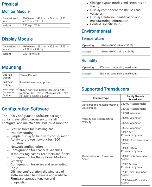
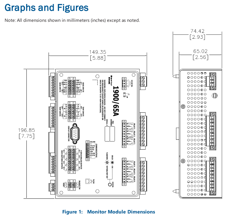
Display Module
The 1900/65A supports an optional display/keypad to view channel information or make minor configuration changes. This allows the 1900/65A to operate as a stand-alone package. If desired, the user can mount the display up to 75 metres (250 feet) from the Monitor Module.
Specifications
Inputs
Transducer Inputs
Users can configure Channels 1 through 4 to accept input from acceleration, velocity or displacement transducers.
Transducer Channel Types
Channel Types define the functionality for processing that will be applied to an input signal and the kind of variables or measurement values that will be derived from this input. Channel Types also define the kind of sensor that must be used. Transducer Channel Types include:
Acceleration or Reciprocating Acceleration
Velocity or Reciprocating Velocity
Radial Vibration (shaft vibration)
Thrust (shaft axial displacement)
Position
Speed
Acceleration and Reciprocating Acceleration Channel Types
The Acceleration Channel Type and Reciprocating Acceleration Channel Type support two- and three-wire acceleration sensors. The Reciprocating Acceleration
channel type has timed OK channel defeat disabled.
Acceleration Variables and Reciprocating Acceleration Variables
Acceleration Variables and Reciprocating Acceleration Variables are filtered and
processed measurements from raw transducer signals. The Acceleration
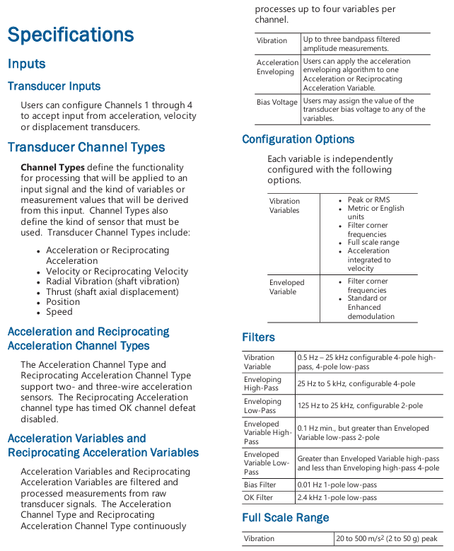
Channel Type and Reciprocating Acceleration Channel Type continuously processes up to four variables per channel.
Vibration:Up to three bandpass filtered amplitude measurements.
Acceleration :Users can apply the acceleration enveloping algorithm to one Acceleration or Reciprocating Acceleration Variable.
Enveloping:Bias Voltage Users may assign the value of the transducer bias voltage to any of the variables.
Filters
Vibration Variable: 0.5 Hz – 25 kHz configurable 4-pole high pass, 4-pole low-pass
Enveloping High-Pass:25 Hz to 5 kHz, configurable 4-pole
Enveloping Low-Pass:125 Hz to 25 kHz, configurable 2-pole
Enveloped Variable High Pass: 0.1 Hz min., but greater than Enveloped Variable low-pass 2-pole
Enveloped Variable Low Pass:Greater than Enveloped Variable high-pass and less than Enveloping high-pass 4-pole
Bias Filter:0.01 Hz 1-pole low-pass
OK Filter:2.4 kHz 1-pole low-pass
Full Scale Range
Vibration:20 to 500 m/s2 (2 to 50 g) peak and RMS
Enveloped:20 to 500 m/s2 (2 to 50 g) peak and RMS
Integrated:10 to 100 mm/s (0.4 to 4 in/s) peak and RMS
Bias Voltage:-24 V
Accuracy
Vibration Variables: ±1% of full scale range
Input Impedance
3-wire Voltage Mode;10 kΩ
Velocity and Reciprocating Velocity Channel Type
The Velocity Channel Type and Reciprocating Velocity Channel Type support two-wire and three-wire piezo velocity sensors.
Velocity Variables and Reciprocating Velocity Variables
Velocity Variables and Reciprocating Velocity Variables are filtered and processed measurements from raw transducer signals. The Velocity Channel Type and Reciprocating Velocity Channel Type support up to four continuously calculated variables per channel.
Vibration
Up to three bandpass filtered amplitude measurements
Bias Voltage
Users may assign the value of the transducer bias voltage to any of the variables.
Configurable Options
Each variable is independently configured with the following options.
Vibration Variables:
Peak or RMS Metric or English units
Filter corner frequencies
Full-scale range
Velocity integrated to displacement
Filters
Vibration Variables:0.5 Hz to 5.5 kHz, configurable 8-pole high pass, 4-pole low-pass
Bias Filter:0.09 Hz 1-pole low-pass
OK Filter:2.4 kHz 1-pole low-pass
Full Scale Range
Vibration:10 to 50 mm/s (0.5 to 2 in/s) peak and RMS
Integrated:100 to 500 μm (5 to 20 mils) peak to peak
Bias Voltage:-24 V
Accuracy
Vibration Variables: ±1% of full scale range
Input Impedance
3-Wire Voltage Mode:10 kΩ
Compliance and Certifications
FCC
This device complies with part 15 of the FCC Rules.
Operation is subject to the following two conditions:
This device may not cause harmful interference.
This device must accept any interference received, including interference that may cause undesired operation.
EMC
EN 61000-6-2: 2005
EN 61000-6-4: 2007 +A1:2001
EMC Directive 2014/30/EU
Electrical Safety
EN 61010-1: 2010
LV Directive 2014/35/EU
ATEX
EN 60079-0: 2012
EN 60079-15: 2010
ATEX Directive 2014/34/EU
RoHS
RoHS Directive 2011/65/EU
Maritime
ABS 2009 Steel Vessels Rules
1-1-4/7.7,4-8-3/1.11.1,4-9-7/13
Hazardous Area Approvals
This monitor is not certified for installation in Class 1 Div 1 locations, but it will support transducers installed in Div 1 locations via the use of galvanic isolators and barriers. If galvanic isolators are used, no change is necessary to the installation. A removable ground jumper allows the monitor to support zener barrier installations. Removing the jumper will disconnect circuit common from chassis at the monitor so that chassis can be connected at the barrier.
Special Considerations
Hazardous area installations require relay contact voltages below 30 Vac rms, or 30 Vdc to minimize hazard.Hazardous area installations require relay contact amperages below 5 Amps DC, or AC to minimize hazard

- YOKOGAWA
- Reliance
- ADVANCED
- SEW
- ProSoft
- WATLOW
- Kongsberg
- FANUC
- VSD
- DCS
- PLC
- man-machine
- Covid-19
- Energy and Gender
- Energy Access
- Renewable Integration
- Energy Subsidies
- Energy and Water
- Net zero emission
- Energy Security
- Critical Minerals
- A-B
- petroleum
- Mine scale
- Sewage treatment
- cement
- architecture
- Industrial information
- New energy
- Automobile market
- electricity
- Construction site
- HIMA
- ABB
- Rockwell
- Schneider Modicon
- Siemens
- xYCOM
- Yaskawa
- Woodward
- BOSCH Rexroth
- MOOG
- General Electric
- American NI
- Rolls-Royce
- CTI
- Honeywell
- EMERSON
- MAN
- GE
- TRICONEX
- Control Wave
- ALSTOM
- AMAT
- STUDER
- KONGSBERG
- MOTOROLA
- DANAHER MOTION
- Bentley
- Galil
- EATON
- MOLEX
- Triconex
- DEIF
- B&W
- ZYGO
- Aerotech
- DANFOSS
- KOLLMORGEN
- Beijer
- Endress+Hauser
- schneider
- Foxboro
- KB
- REXROTH
- YAMAHA
- Johnson
- Westinghouse
- WAGO
- TOSHIBA
- TEKTRONIX
- BENDER
- BMCM
- SMC
- HITACHI
- HIRSCHMANN
- XP POWER
- Baldor
- Meggitt
- SHINKAWA
- Other Brands
- UniOP
- KUKA
- IBA
- Beckhoff
- ADLINK
106
-
Beckhoff EP9224-0037 - 4-Channel Power Distribution Box EtherCAT
-
Beckhoff CX2900-0026 - Solid State Flash Memory Card 20GB CFast
-
Beckhoff BK7500 - SERCOS Interface Fieldbus Bus Coupler Terminal
-
Beckhoff Ep2328-0002 - 4-Channel Input 4-Channel Output EtherCAT Box IP67
-
Beckhoff CX1020-0111 - Controller Kit Combo Interface Modules
-
B&R X20AI2237 - X20 System Analog Input Interface Module
-
Beckhoff CP2221-0010 - Multi-Touch Built-In Panel PC Touchscreen
-
Beckhoff CX1500-M310 - Fieldbus Master Interface Module 24V
-
Beckhoff CX2100-0904 - Power Charging Module Smart UPS Extension
-
Beckhoff CP3918-0000 - Multi-Touch Control Panel 18.5-Inch Monitor
-
Beckhoff CP2915-0000 - 15-Inch Multi-Touch Built-In Control Panel
-
Beckhoff CP7037-1027 - HMI Industrial Control Panel Built-In PC
-
Beckhoff EL3152 - 2-Channel Analog Input Terminal 4-20mA EtherCAT
-
Beckhoff CP6607-0000-0020 - 5.7-Inch Built-In Panel PC HMI Touch
-
Beckhoff EJ1809-0000 - 16-Channel Digital Input Pluggable Signal Level Terminal
-
Beckhoff AM8563-0N10-0000 - Synchronous Servo Motor
-
Beckhoff AX2006-S60600-520 - Compact Servo Drive Inverter
-
Beckhoff AM8053-0K20-0000 - Servo Motor with Planetary Gearbox AG3210
-
Beckhoff AM8042-0FH1-0000 - Synchronous Servo Motor
-
Rexroth R911338600 - IndraControl V HMI Terminal Beckhoff PCI Card FC9002
-
Beckhoff AX5125-0000 - 3 Phase Industrial Servo Drive 1000Hz
-
Beckhoff EP2328-0002 - 4-Channel Digital Input 4-Channel Output EtherCAT Box
-
B&R 7CP476-02 - System 2005 RTD CPU Module 3IF681.86 Interface
-
Beckhoff AX8620-0000-0000 - Power Supply Module Axis Drive System
-
Beckhoff CX1010-0111 - PLC Module CPU Controller 24V
-
Beckhoff AM8043-0H10-0000 - Synchronous Servo Motor
-
Beckhoff C6240-1009 - Control Cabinet Industrial PC Mainframe
-
Beckhoff BX8000-0000 - Bus Terminal Controller HW 4.4 Standalone
-
Beckhoff CP7721-1089-0020 - 12.1-Inch Touch Screen HMI Panel PC
-
Beckhoff CP7132-0001 - Industrial Built-In Panel PC Screen
-
Beckhoff CP2912-0010 - Multi-Touch Built-In Control Panel Display
-
Beckhoff CP2915-0000 - 15-Inch Multi-Touch Built-In Control Panel
-
Beckhoff AM8532-1EN0-0000 - Synchronous Servo Motor
-
Beckhoff AX5203-0000 - 2-Channel Digital Compact Servo Drive
-
Beckhoff CX2020-0141 - Embedded PC Core CPU Module
-
Beckhoff CP6832-0002-0010 - Built-In Industrial Control Panel Display
-
Beckhoff CX5020-0112 - Embedded PC CPU Control Module
-
Beckhoff CX5140-0175 - 4GB Embedded PC CPU Unit 24V
-
Beckhoff EL3681-0030 - Digital Multimeter Calibration Terminal EtherCAT
-
Beckhoff CP7201-1000-0000 - Industrial PC Touch Screen HMI Monitor
-
Beckhoff CP7232-1001-0000 - Industrial Panel PC Touch Screen
-
Beckhoff C6930-1032-0040 - Control Cabinet Industrial PC System
-
Beckhoff AX5125-0000 - 3 Phase Industrial Servo Drive 1000Hz
-
Beckhoff CP3916-1424-0000 - Multi-Touch Built-In Control Panel
-
B&R 1900071142 - Lemoine Fieldbus Communication Interface Module
-
Beckhoff EL2872 - 16-Channel Ribbon Cable Digital Output Terminal
-
Beckhoff CX2030-0120 - Embedded PC CPU Base Module Controller
-
Beckhoff CP3919-0000 - 19-Inch Multi-Touch Control Panel Touchscreen
-
Beckhoff AX5101-0000-0202 - Servo Driver Compact Intelligent Drive 180V
-
Beckhoff CX5130-0135 - Embedded PC Controller Module
-
Beckhoff CP3719-1061-0010 - Multi-Touch Panel PC Outer Housing Enclosure
-
Beckhoff CP3919-1033-0000 - 19-Inch Touch Industrial Panel Keyboard
-
Beckhoff CX5020-0111 - Embedded PC PLC CPU Module
-
Beckhoff FC5102-0000 - 2-Channel CANopen PCI Control Board Card
-
Beckhoff CX9001-1101 - Embedded PC CPU Network I/O System Module
-
Beckhoff CX1100-0920 - Smart Position Sensor Interface Module
-
B&R 4P3040.01-490 - Operator Panel PLC Interface Communication Module
-
Beckhoff CP2612-0000 - Dual-Touch Built-In Panel PC HMI
-
Beckhoff CP7002-1043-0010 - Touchscreen Display HMI Panel Terminal
-
Beckhoff CX9020-0115 - Embedded PC Controller Module
-
Beckhoff CX5140-0155 - 4GB Embedded PC CPU Module Die Industry
-
B&R 7DI435.7 - System 2005 Universal Digital Input Output Module
-
Bihl+Wiedemann BWU1568 - AS-i Master to Profibus Gateway Module
-
Beckhoff C6920-0070 - Control Cabinet Industrial PC 8GB Win 10
-
B&R X20AI2322 - 2-Channel Temperature Analog Input Module
-
Beckhoff CP2912-0000 - 12-Inch Touchscreen Display Monitor Screen
-
Beckhoff CP6022-1001-0010 - 15-Inch Built-In Control Panel
-
Beckhoff AM8031-0D10-0000 - Synchronous Servo Motor
-
Beckhoff CX5010-0111 - Embedded PC Controller CPU Module
-
Beckhoff CP7232-1000-0000 - Industrial Panel PC Touch Display Screen
-
Beckhoff CP7802-0011-0000 - 15-Inch Industrial Touchscreen Control Panel
-
Beckhoff C6320 - Control Cabinet Industrial PC
-
Beckhoff CX1030-0012 - Basic CPU Module Windows CE 6.0
-
Beckhoff CP2919-0000 - Installation Multi-Touch Control Panel
-
Beckhoff CX1020-0000 - Controller Set Stack System Pack
-
B&R 3DO480.6 - System 2005 Digital Output Module
-
Beckhoff EL3101 - 1-Channel Analog Input Terminal Differential +/-10V
-
Beckhoff AX8108-0200-0000 - Axis Feed Module Servo Drive
-
Beckhoff CP7802-1241-0010 - 15-Inch Industrial Touchscreen Control Panel
-
Beckhoff FC2002-0000 - 2-Channel Lightbus Data Acquisition PCI Card
-
Beckhoff CX5120-0155 - 2GB Embedded PC Intel Atom Controller
-
Beckhoff Cx9020-0111 - 1GB Basic CPU Module Embedded PC
-
Beckhoff CP6901-0001-0000 - 12-Inch Economy Built-In Control Panel
-
Beckhoff CX9020-0111 - Embedded PC CPU Basic Module
-
Beckhoff CX5130-0100 - 4GB Embedded PC CPU Module
-
Beckhoff CP2715-0010 - Multi-Touch Built-In Panel PC
-
Beckhoff CX2033-0175 - Embedded PC CPU Module Core i7
-
Beckhoff CP7201-1000-0000 - 12-Inch Touchscreen Panel PC AMAT Green Box
-
Beckhoff EL4038 - 8-Channel Analog Output Terminal 0-10V EtherCAT
-
Beckhoff CP6802-0000-0000 - Built-In Control Panel HMI Screen
-
Beckhoff CP6500-1012-0060 - Control Cabinet PC Interface Unit
-
Beckhoff FC5202-0000 - 2-Channel DeviceNet Master PCI Interface Card
-
Beckhoff CP6606-0001-0020 - 7-Inch Economy Panel PC Touch
-
Beckhoff CP2921-0010 - Multi-Touch Integrated Control Panel Display
-
Beckhoff CP7802-0001-0010 - 15-Inch Touch Screen Control Panel HMI
-
Beckhoff C6920-0050 - Control Cabinet Industrial PC
-
Beckhoff BK9105 - EtherNet/IP Bus Coupler Network Interface
-
Beckhoff 31 Modules - Bus Terminal Slice I/O Lot Assortment
-
Beckhoff CX2020-0120 - Embedded PC Basic CPU Module 8GB CFast Card
-
Beckhoff CP7001-0000 - HMI Control Panel Touch Screen
-
B&R 7EX484.50-1 - System 2005 Controller Base Module Slots
-
Beckhoff EK1322 - 2-Port EtherCAT P Extension Feed-In Terminal
-
Beckhoff CP6606-0001-0020 - 7-Inch Single-Touch Economy Panel PC
-
Beckhoff CP6607-0001-0000 - Economy Installation Operator Panel PC 5.7-Inch
-
Beckhoff AX5103-0000-0200 - Digital Compact Servo Driver 3 Phase
-
Beckhoff CP7802-0001-0010 - 15-Inch Touch Screen Control Panel
-
Beckhoff AX8620 - Power Supply Module Axis System
-
Beckhoff CX2030-0121 - Embedded PC Controller Module
-
Beckhoff CP6606-0001-0020 - 7-Inch Economy Panel PC Touch Screen
-
Beckhoff CX2030-0121 - Embedded PC CPU Module Windows Standard 7
-
Beckhoff BX3100-0000 - PROFIBUS DP Bus Terminal Controller
-
Beckhoff CX1020-0000 - Controller Set with Power Supply Unit
-
Beckhoff EK1100 - EtherCAT Coupler Terminal Module Set
-
Beckhoff CP7002-1043-0010 - HMI Display Panel with Control Panel Bracket
-
Beckhoff AM8031-0D10-0000 - Synchronous Servo Motor
-
Beckhoff CX5130-0175 - Embedded PC 4GB RAM Controller
-
Beckhoff CX5130-0155 - Embedded PC Automation Controller
-
Beckhoff C6930-0010 - Control Cabinet Industrial PC Core Duo
-
Beckhoff CP3924-0000 - Multi-Touch Control Panel Display
-
Beckhoff AM8023-0F20-0000 - Synchronous Servo Motor
-
B&R KL3362 - Bus Terminal Thermocouple Input Module
-
Beckhoff AL2006-0000-0000 - Linear Servo Motor Three Phase
-
Beckhoff CX5140-0155 - Embedded PC CPU Controller Module
-
Beckhoff FC9002 - Ethernet PCI Network Interface Card
-
Beckhoff CP7203-0021-0040 - Built-In Panel PC 19-Inch Touch Screen
-
Beckhoff C6930-0020 - Control Cabinet Industrial PC HDD CF Card
-
Beckhoff CX2900-0033 - Memory Card CFast Storage
-
Beckhoff CP6201-0001-0020 - Built-In Panel PC Display

K-JIANG

Add: Jimei North Road, Jimei District, Xiamen, Fujian, China
Tell:+86-15305925923