
K-WANG


Bentley 3500/42 Proximitors ®/ Earthquake monitoring module
Bentley 3500/42 Proximitors ®/ Earthquake monitoring module
Product Overview
Core functions
3500/42 Proximitor ®/ The earthquake monitoring module is a four channel monitoring device that can receive input signals from a proximity probe and seismic sensors, and achieve monitoring functions such as radial vibration, thrust position, eccentricity, differential expansion, acceleration, and velocity through configuration. Its core function is to drive alarm output by comparing the current machine vibration value with the preset alarm threshold, and provide machine status data for operation and maintenance personnel.
Key Features
TMR architecture: Supports triple modular redundancy (TMR) configuration, avoids single point of failure through a 2 out of 3 voting mechanism, and ensures system reliability.
Flexible configuration: Customize channel types, alarm thresholds, filtering parameters, etc. through 3500 rack configuration software to adapt to different monitoring scenarios.
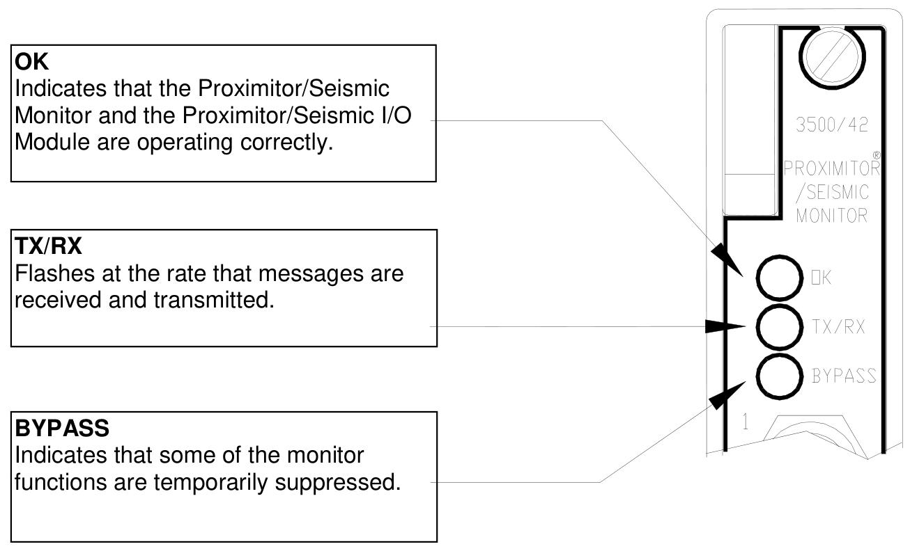
Real time diagnosis: Built in self checking function, quickly locate faults through LED indicator lights and event logs.
Safety certification: Compliant with standards such as IEC 61508, suitable for hazardous areas (such as Class I, Division 1/2).
Product Architecture and Working Principle
Hardware Architecture
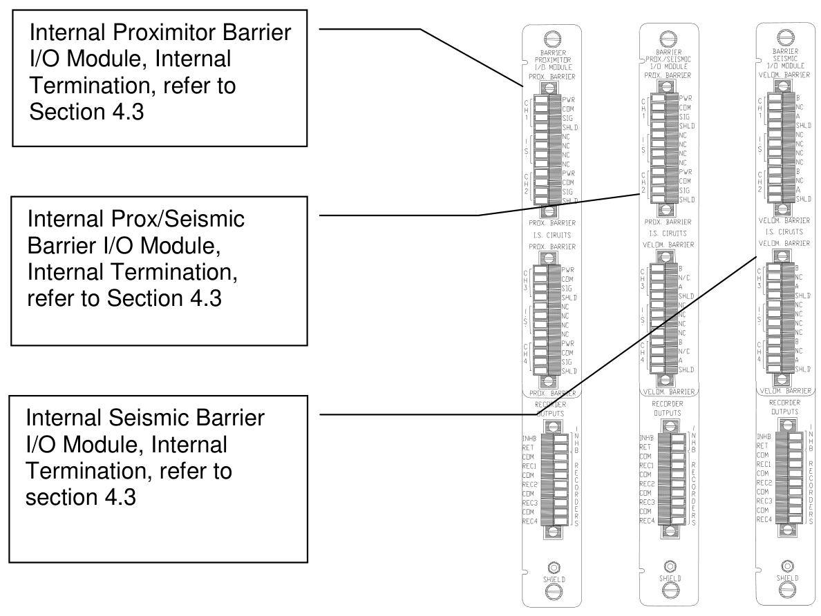
Input module: support multiple I/O modules, including internal terminal, external terminal, TMR terminal and terminal module with barrier, and adapt to different sensor wiring requirements (such as Proximitor, accelerometer, speed sensor).
Signal processing: Each channel integrates filtering, amplification, and digitization circuits, supporting bandpass, high pass, and low-pass filtering, with a configurable frequency response range (such as radial vibration channels supporting 1 Hz to 4000 Hz).
Communication interface: communicates with other modules through the rack backplane, supports serial protocols such as RS-232/485, and can be connected to the upper computer for data monitoring.
TMR redundancy mechanism
Voting logic: In the TMR configuration, three monitoring modules vote 2 out of 3 for the input signal. If the deviation between the output of one module and that of other modules exceeds the set threshold (such as% Comparison), event logging will be triggered.
Input configuration:
Bus configuration: A single non redundant sensor signal is distributed to three modules through the bus.
Discrete configuration: Three redundant sensors are connected to three modules respectively to improve reliability.
Data output and status monitoring
Proportional value output: Output different parameters based on channel type, such as Direct (peak to peak), 1X/2X amplitude, phase lag, etc. for radial vibration; Gap (gap voltage) and Direct (axial displacement) at the thrust position.
Status identification: Feedback module health status, communication status, and alarm events through LED (OK, TX/RX, BYPASS) and event logs (System Event List, Alarm Event List).
Configuration Guide
Software Configuration Tool
Use 3500 Rack Configuration Software for parameter settings, with core configuration items including:
Channel type: Select radial vibration, thrust position, etc. Different types correspond to different filtering and scaling factors.
Full range: For example, radial vibration Direct can choose 0-10 mil pp (peak to peak), and acceleration can choose 0-20 g pk (peak to peak).
Alarm threshold: Set the Alert/Alarm 1 and Danger/Alarm 2 thresholds for each proportional value, and support lag adjustment (e.g., hysteresis is 1/64 of full scale).
Filter parameters: Set the cut-off frequency of the high/low-pass filter (e.g. acceleration channel supports 3 Hz to 30 kHz).
Example of Key Parameter Configuration
Radial vibration channel:
Select a 3300-8 mm Proximitor sensor and set the Scale Factor to 200 mV/mil.
Set the 1X Amplitude full-scale to 10 mil pp, the Alert threshold to 6 mil pp, the Danger threshold to 8 mil pp, and the delay time to 1 second.
Thrust position channel:
The Zero Position voltage is set to -9.75 Vdc (corresponding to the center value of the gap), the full range is set to 25-0-25 mil, and the direction is set to "Forward Probe" (displacement increases when the rotor moves towards the probe).
Key points of TMR configuration
Three monitoring modules need to be installed adjacent to each other and configured with Comparison Voting (if comparing 1X Amplitude, a deviation of 5% is allowed).
Bussed External Termination Block is used for bus configuration, while three independent sensors and terminal blocks are used for discrete configuration.
I/O modules and wiring
Module type and function
Internal terminal module: directly connected to sensors and recorders, suitable for non hazardous areas, wiring should pay attention to electrostatic protection (such as using anti-static wrist straps).
Internal Barrier Module: Integrated Zener Barrier, suitable for explosion-proof areas (such as Class I, Division 1), to restrict energy flow into hazardous areas.
External terminal module: Connect the sensor with a 25 pin cable and the recorder with a 9-pin cable to simplify the internal wiring of the rack.
Wiring specifications
Proximitor sensor: The power supply (PWR) is connected to -24 Vdc, the signal (SIG) is connected to the channel input, and the shielding layer (SHLD) is grounded.
Seismic sensors (such as Velomitor) require series connection of resistors and capacitors (such as 4 k Ω resistors+10 μ F capacitors) for signal conditioning.
TMR wiring: In discrete configuration, three sensors are connected to independent channels of three modules, and in bus configuration, sensor signals are shared through a Bussed Terminal Block.
Maintenance and testing
Regular verification testing
Testing cycle: It is recommended to conduct it once a year. If the equipment is a critical unit or operates in harsh environments, it can be shortened to once every quarter.
Testing equipment: function generator, multimeter, oscilloscope, Keyphasor Multiplier/Diverder, etc.
Test steps (taking radial vibration channel as an example):
Simulate sensor signals (such as a 100 Hz sine wave with a peak to peak value of 2 V).
Verify the display accuracy of proportional values such as Direct and 1X Amplitude (error ≤ ± 1% of full scale).
Trigger Alert/Arm 1 and Danger/Arm 2 thresholds, confirm that the alarm delay time is consistent with the configuration.
Disconnect the input signal and verify the OK state recovery time (Timed OK Channel Defeat set to 30 seconds).
Scale factor and zero position adjustment
Scale Factor: Used to calibrate the linearity deviation of sensors, such as the default 200 mV/mil for 3300-8 mm Proximitors, which can be adjusted by ± 15%.
Zero Position: For channels such as thrust position and eccentricity, adjust the voltage to make the displayed value zero (such as setting the zero position of thrust position to -9.75 Vdc, corresponding to mechanical zero position).
Recorder output verification
The 4-20 mA output should correspond to the full-scale proportional value. For example, when the full-scale is 10 mil pp, 20 mA corresponds to 10 mil pp, and 4 mA corresponds to 0 mil pp, with an error of ≤± 1%.
Troubleshooting
LED fault diagnosis
OK light off: It may be due to module failure, hardware malfunction, or sensor disconnection. Check the power and wiring, restart the module, or replace spare parts.
BYPASS light on: The channel is bypassed by software or the sensor is faulty. Check the Software Switches configuration and confirm that the sensor is in an OK state.
TX/RX light does not flash: communication failure, check the rack backplane connection and serial port parameters (baud rate, data bits).
Analysis of System Event List
Event 11 (Flash Memory Failure): Flash memory failure, module replacement required immediately.
Event 62 (I/O Module Mismatch): The I/O module type does not match the software configuration. Check the module model and reconfigure it.
Event 493 (Kph Lost): Keyphasor signal loss. Check the Keyphasor sensor and wiring to confirm if the speed is within the valid range (60-60000 cpm).
Common alarm handling
Alert/Arm 1 trigger: If the vibration value exceeds the threshold, check whether the machine is unbalanced, misaligned, or has bearing faults.
Trigger of Danger/Arm 2: Emergency stop condition, immediately stop the machine and troubleshoot equipment faults. If the shaft displacement exceeds the limit, it may cause dynamic and static friction.
Technical specifications and ordering information
key parameter
Input impedance: Proximitor channel 10 k Ω, TMR configuration with bus mode 50 k Ω and discrete mode 150 k Ω.
Frequency response: The radial vibration Direct channel supports 1 Hz-4000 Hz, and the acceleration channel supports 3 Hz-30 kHz.
Environmental conditions: Operating temperature -30 ℃~65 ℃ (non barrier module), storage temperature -40 ℃~85 ℃, humidity ≤ 95% non condensing.
Order Parts
Monitor module: 3500/42-01-00 (discrete internal terminal, no authentication), 3500/42-03-01 (TMR external terminal, CSA authentication).
Spare parts: I/O module (such as 128229-01), terminal block (125808-02 Euro style), cable (129525-0010-01, 10 foot assembly cable).
Safety and Compliance
Explosion proof certification: With barrier module supporting Class I, Division 1 (Groups A-D) and EEx ia IIC, suitable for explosive gas environments.
Static protection: When operating the module, wear an anti-static wrist strap and store it in a conductive bag to prevent static electricity from damaging the circuit board.
Maintenance warning: When hot plugging modules, ensure that the rack is powered off to avoid the risk of short circuit or electric shock caused by live operation.
- YOKOGAWA
- Reliance
- ADVANCED
- SEW
- ProSoft
- WATLOW
- Kongsberg
- FANUC
- VSD
- DCS
- PLC
- man-machine
- Covid-19
- Energy and Gender
- Energy Access
- Renewable Integration
- Energy Subsidies
- Energy and Water
- Net zero emission
- Energy Security
- Critical Minerals
- A-B
- petroleum
- Mine scale
- Sewage treatment
- cement
- architecture
- Industrial information
- New energy
- Automobile market
- electricity
- Construction site
- HIMA
- ABB
- Rockwell
- Schneider Modicon
- Siemens
- xYCOM
- Yaskawa
- Woodward
- BOSCH Rexroth
- MOOG
- General Electric
- American NI
- Rolls-Royce
- CTI
- Honeywell
- EMERSON
- MAN
- GE
- TRICONEX
- Control Wave
- ALSTOM
- AMAT
- STUDER
- KONGSBERG
- MOTOROLA
- DANAHER MOTION
- Bentley
- Galil
- EATON
- MOLEX
- Triconex
- DEIF
- B&W
- ZYGO
- Aerotech
- DANFOSS
- KOLLMORGEN
- Beijer
- Endress+Hauser
- schneider
- Foxboro
- KB
- REXROTH
- YAMAHA
- Johnson
- Westinghouse
- WAGO
- TOSHIBA
- TEKTRONIX
- BENDER
- BMCM
- SMC
- HITACHI
- HIRSCHMANN
- XP POWER
- Baldor
- Meggitt
- SHINKAWA
- Other Brands
- UniOP
- KUKA
- IBA
- Beckhoff
- ADLINK
-
ADLINK HPCI-14S12U - Industrial Control Backplane 12PCI Backplane PCI-14S Passive Backplane
-
ADLINK PCIe-GIE74C - image acquisition card 4-CH GigE Vision PoE+ Frame Grabber
-
ADLINK PCI-8164 - control card 4-Axis Advanced Motion Controller Board
-
ADLINK PCIe-U304 - 4 Port USB3 PCIe Frame Grabbers USB Screw Hole Card
-
ADLINK PCI-9112 - Multi-Function Data Acquisition Card DAQ Card
-
ADLINK PCI-7432 - 51-12013-0A50 4-CH Isolated Numérique I/O PCI Cartes Digital I/O Card
-
ADLINK PCA-6106P3-0C1 REV.C1 - backplane 6-Slot Passive Backplane Board
-
ADLINK PCI-7224 - 24-CH Opto-Isolated Digital I/O PCI Board
-
ADLINK CPCI-7433R(G) - Digital Input Board Rear I/O CompactPCI Card
-
ADLINK EBP-13E4 - 51-46703-0A30 Industrial PC Backplane Passive Backplane
-
ADLINK PCIE-HDV62 - Image acquisition card High Definition Video Frame Grabber
-
ADLINK EBP-13E4 - 51-46703-0A30 Industrial Backplane Board Passive Backplane
-
ADLINK 90111-B1 / CPCI-6770 - PCB CPU MODULE CompactPCI Single Board Computer
-
ADLINK PCI-7248 - DATA ACQUISITION PCI CARD 48-CH Parallel Digital I/O Board
-
ADLINK PCI-7230 - 51-12003-0a50 board PCI7230 32-CH Isolated Digital I/O Card
-
ADLINK PCI2A000CB - 51-20000-0B30 Multi-Function DAQ Card Baseboard
-
ADLINK PCI-8134-005 - 4-Axis Motion Controller Card
-
ADLINK PCI-7224 - 24-CH Opto-Isolated Digital I/O PCI Card
-
ADLINK PCI-7434 - 64-CH Isolated Digital Output Card
-
ADLINK PCI-8132 - motion control card 2-Axis Servo & Stepper Controller
-
ADLINK PCI-8134 - Motion Controller PCI Card 4-Axis Controller Board
-
ADLINK PCI-8164 - Motion Control Card 51-12406-0A40 4-Axis Controller
-
ADLINK 51-12001-0C20 - Circuit Board Data Acquisition Interface Module Hardware
-
ADLINK NuPR0-840 - industrial control motherboard Full-Size PICMG CPU Board
-
ADLINK PCI-7444 - 51-12023-0A10 card 128-CH Isolated Digital Output Board
-
ADLINK PCI-1612B - data acquisition card 4-Port RS-232/422/485 Serial Communication Card
-
ADLINK PCI-6208V 009 - 8/16-CH 16-Bit Analog Output Cards PCB-I-E-482=6BX3
-
ADLINK NUPRO-935A/LV - industrial control motherboard Full-Size PICMG SBC Board
-
ADLINK PCI-9114DG - Multi-Function DAQ Card Data Acquisition PCI Card
-
ADLINK ACL-7130 - Data acquisition card Isolated Digital I/O Board
-
ADLINK ABX-6300D-4E1-BP - board ABX6300D4E1BP Video Interface Expansion Card
-
ADLINK CPCI-6940 - CPCI-6940/D1539/M16-0(EA)-000E 6U CompactPCI Processor Board
-
ADLINK NuPRO-760 - industrial control motherboard Half-Size PICMG SBC CPU Board
-
ADLINK IMB-M42H (G)-0020 - industrial control motherboard LGA1155 Micro-ATX Mainboard
-
ADLINK RTV-24 / PCI-MP4S - 51-12519-1C30 4-Channel Real Time Video Capture Board
-
ADLINK PCI-8134 - 4-Axis Servo & Stepper Motion Controller Card
-
ADLINK MXC-6101D - V.PC000.002.ST.00 Box PC Configurable Embedded Computer
-
ADLINK PCI-8134A - 51-12421-0A10 Motion Control Card 4-Axis Controller Card
-
ADLINK DIN-100S / DIN-100SA1 - Technology SCSI-II TB 100-PIN Terminal Block Board
-
ADLINK DIN-812M001 / DIN812M001 - 51-14034-0A1 51140340A1 Terminal Module Breakout Interface
-
ADLINK PCI-8164 - Servo motion control 4-Axis Advanced Controller Card
-
ADLINK PCIe-GIE64 - Acquisition card GigE Vision PoE+ Frame Grabber
-
ADLINK M-302 - Industrial control motherboard ATX PC Board Mainboard
-
ADLINK PCI-8134 - Motion Controller PCI Card 4-Axis Controller Board
-
ADLINK PCI-RTV24 - Image capture card Analog Video Frame Grabber
-
ADLINK PCI-8102 - Motion control card 2-Axis Servo & Stepper Controller Board
-
ADLINK PCI-9112 REV.B1 - Card Multi-Function Data Acquisition Card
-
ADLINK HSI-DI32-M-N / HSL-TB32-M-DIN - Discrete I/O MODULE Distributed Automation Module System
-
ADLINK PCI-7296 - IO card REV.A3 96-CH Parallel Digital I/O Card
-
ADLINK DIN-814P-A4 / 814Y - terminal board Motion Control Interface Block
-
ADLINK DIN-814P-A4 - 51-14056-0A10 PCB-I-E-2736=ZA01 Screw Terminal Board Breakout
-
ADLINK M-322 - motherboard Industrial Control Computer Mainboard
-
ADLINK NUPRO-406 REV:B1 - industrial control motherboard Full-Size PICMG CPU Board
-
ADLINK AMP-204C - card DSP-Based 4-Axis Advanced Pulse-Train Controller
-
ADLINK HPCI14S REV.B1 - industrial computer baseboard 14-Slot Passive Backplane
-
ADLINK PCI-7250 - 8-CH Relay Output & 8-CH Isolated DI PCI Card
-
ADLINK EBP-13E2 - baseplate Passive Backplane Industrial Computer Chassis Board
-
ADLINK LPCI-3488A - PCI-GPIB card 51-12801-0A30 acquisition card IEEE-488 Interface Board
-
ADLINK PCI-6216V-GL - 51-12201-0C30 16-CH 16-Bit Voltage Analog Output Card
-
ADLINK ACL-8454 - 16-CH Isolated Digital I/O & 4-CH Counter Card
-
ADLINK HPCI-9S7U - backplane Passive Backplane Compatible with NuPRO-A301 852 841 842
-
ADLINK DAQ-2010-007 - Simultaneous-Sampling Multi-Function Data Acquisition Card
-
ADLINK MP-C154 - 51-64205-0A10 Motion Control Card 4-Axis Controller Board
-
ADLINK MXE-202/mSSD16B/WiFi-BT - Matrix Rugged I/O Platform Embedded Fanless Computer
-
ADLINK CM-920-R-17 - PC/104-Plus Single Board Computer Module Intel Celeron M
-
ADLINK PCI-7250 NSMP - 8-CH Relay Output & 8-CH Isolated DI Card
-
ADLINK PCI-8164 - 4-Axis Motion Controller PCI Card W/ Cable and Breakout Box
-
ADLINK EMX-100 - Ethernet-based 4-axis Motion Controllers Distributed Motion Module
-
ADLINK PCI-8134A - Press control card 4-Axis Motion Controller Board
-
ADLINK M-845EG REV:3.2 - industrial motherboard Pentium 4 Socket 478 Micro-ATX
-
ADLINK PCI-9114A Rev A2 DG - card High-Resolution Multi-Function Data Acquisition Board
-
ADLINK IEC-915GV - REV 1.1 Industrial motherboard Socket 478 CPU Board
-
ADLINK PCI-9111DG(G) - Data Acquisition Card Multi-Function DAQ Card
-
ADLINK HPCI-15S10 REV:B2 - Industrial computer base plate Passive Backplane Board
-
ADLINK NuPR0-840 / NuPR0-840DV - industrial control motherboard Full-size PICMG CPU Board
-
ADLINK RTV-24 / PCI-MP4S - 51-12519-1C30 4-Channel Real Time Video Capture Board
-
ADLINK NUPRO-780 - industrial control motherboard Pentium III Single Board Computer
-
ADLINK PCI-7296 - 0050 card 96-CH Opto-Isolated Parallel DIO Card Set
-
ADLINK NUPRO-780 - industrial control motherboard PICMG Full-Size SBC
-
ADLINK PCI-7248 - 51-12006-0A3 002 Pci 7248 48-CH Parallel Digital I/O Card
-
ADLINK PCI-7230 - 32-CH Isolated Digital I/O Card
-
ADLINK AMP-204C - motion control card 4-Axis Advanced Controller Board
-
ADLINK PCI-1714UL - Card Ultra High-Speed 4-CH Simultaneous Sampling DAQ
-
ADLINK NuPRO-E330 - industrial computer equipment motherboard PICMG 1.3 SHB SBC
-
ADLINK AMP-204C - DSP-Based 4-Axis Advanced Pulse-Train Motion Controller Module
-
ADLINK PCI-7256 - 001 51-12206-0A2 REV.A2 LPCI-7256 16-CH Latching Relay Output Card
-
ADLINK ND6050 - NUDAM DIGITAL I/0 MODULE Distributed I/O Unit
-
ASEM BM100 - Box PC Embedded Fanless Industrial Computer
-
ADLINK PCI-7250 - PCI Acquisition Card 8-CH Relay Output & Isolated DI Board
-
ADLINK PCI-8164 - Servo motion control 4-Axis Controller Card
-
ADLINK NuPRO-A40H - Industrial Motherboard 51-41807-1A30 OSP LGA1155 H61
-
ADLINK ADMAX X300 SERVER - 51066010-0A30 motherboard Multi-Processor Mainboard
-
ADLINK CMe-GIE62+ - 51-32903-0A30 control card PC/104-Plus GigE Vision Frame Grabber
-
ADLINK NUPRO-780 - industrial control motherboard Full-Size PICMG SBC CPU Board
-
ADLINK ETX-AT-N270-18/GKTEL - 51-71111-OB10 motherboard ETX CPU Module Board
-
ADLINK DIN-812M - interface module Terminal Block Connection Board
-
ADLINK IMB-M42H - industrial control motherboard LGA1155 Micro-ATX Mainboard
-
ADLINK PXIS-2508 - 8-slot 3U PXI Instrument Chassis Power Hardware Assembly
-
ADLINK AMP-208C - Motion Control card DSP-Based 8-Axis Pulse-Train Controller
-
ADLINK PCI-9111 / PCI-9111DG - Multi-Function Data Acquisition Card DAQ Board
-
ADLINK IEEE-488 GPIB card - Bus Interface Controller Communication Board
-
ADLINK RTV-24 - 51-12519-1C30 image acquisition card Video Frame Grabber Card
-
ADLINK TB-24P/24-01 - Board 24 Way Screw Terminal Breakout Board
-
ADLINK HSL-DI16DO16-DB-NN - 51-23015-0A40 Distributed Discrete I/O Module Set
-
ADLINK PCI-7442 - switch quantity card data acquisition card 64-CH Isolated Card
-
ADLINK ACL-7130 REV. B2 - industrial control capture card Isolated Digital I/O PCI Card
-
ADLINK PCI-6S / PCI6S - Backplane 6-Slot Passive Backplane Chassis Board
-
ADLINK ACL-8113A - card Isolated Digital Input Card
-
ADLINK CPCI-6208V-003 - board cPCI CompactPCI 8-CH Analog Output Card
-
ADLINK DIN-100S-01(G) - SCSI 100-Pin Terminal Block Interface Board
-
ADLINK PCI-7433 - Isolated Digital Input Card 64-CH
-
ADLINK PCI-9812 - Synchronous sampling analog input card High-Speed DAQ Board
-
ADLINK PCI-7434 REV.B1 - PLOTECH PCB-I-E-1182=6EX2 64-CH Isolated Digital Output Card
-
ADLINK PCIe-RTV24 - 51-18016-0A20 4-CH Real-Time Video Capture Card PCIe Frame Grabber
-
ADLINK PCI-8144 / PCI-8144N - Motion control card 4-Axis Stepper Motor Controller
-
ADLINK DIN-68S-01 - terminal board 68-Pin Connector Terminal Block
-
ADLINK MP-C154 - Motion control card 4-Axis Advanced Controller Card
-
ADLINK PCI-7248 (G) - Motherboard 48-CH Parallel Digital I/O Card
-
ADLINK MXE-1301(G) - Intel Atom D2550+NM10 MXE 1300 Series 93-4130-0030 Embedded Computer
-
ADLINK PRO-841 Rev 2.0 / PRO-060907000670 - CPU 2.26GHz & RAM Industrial PC Board
-
ADLINK NuPRO-E330 - Industrial Motherboard System Host Board PICMG 1.3 SHB
-
ADLINK EBP-13E2 - Passive Backplane Industrial Chassis Baseboard
-
ADLINK PCI-8154 - 4-axis Motion Control Card Servo & Stepper Controller Board
-
ADLINK NuPrO-596 REV.B1 - industrial control motherboard Half-size PICMG CPU Board
-
ADLINK PCI-7852 / PCI-7851 - PLOTECH High-Speed Link Control Card Interface Board
-
ADLINK PCI-9112 - 51-12252-0D20 data acquisition card Multi-Function DAQ
-
ADLINK PCI-9112 - Circuit Board 51-12252-0C20 Multi-Function Data Acquisition Card
-
ADLINK NUPRO-761 REV:1.1 - industrial control motherboard PICMG Full-Size CPU Board

K-JIANG

Add: Jimei North Road, Jimei District, Xiamen, Fujian, China
Tell:+86-15305925923