
K-WANG


Woodward PGPL electro-hydraulic actuator/driver(37519 G version)
Alternative value: Used to replace traditional hydraulic mechanical governors such as PG-PL, PGD, PGL, etc., retaining the convenience of the original PG type transmission and connecting rod system, while possessing high precision and flexibility of electronic control.
Woodward PGPL electro-hydraulic actuator/driver
Product core positioning and application scenarios
1. Core positioning
Technology type: Electro hydraulic integrated actuator, including proportional drive interface, capable of receiving electronic controllers (such as Woodward 2301A series, 700 series, etc.) Peak ® The 0-200mA position signal output by the 150 and 505 controllers is controlled by a torque motor and a follow-up pilot valve to drive the output shaft, and coupled with a contactless position sensor to achieve closed-loop control.
Alternative value: Used to replace traditional hydraulic mechanical governors such as PG-PL, PGD, PGL, etc., retaining the convenience of the original PG type transmission and connecting rod system, while possessing high precision and flexibility of electronic control.
2. Scope of application
Adaptation equipment: gas engines, steam turbines (such as power generation turbines, industrial compressor driven turbines);
Hazardous Area Compliance: Compliant with UL certification, suitable for Class I Zone 2, A/B/C/D hazardous environments (models with magnetic electric sensor (MPU) options do not have UL/cUL certification);
Linkage system: It needs to be used in conjunction with an electronic governor, and its core function is to convert electronic control signals into mechanical actions, adjust fuel supply or steam valve opening, and achieve speed/load control.
Core components and technical specifications of the product
The PGPL system consists of two parts: the "actuator" and the "driver". The former is responsible for mechanical action output, while the latter realizes electrical signal conversion and closed-loop control. The specific parameters are as follows:
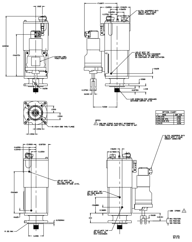
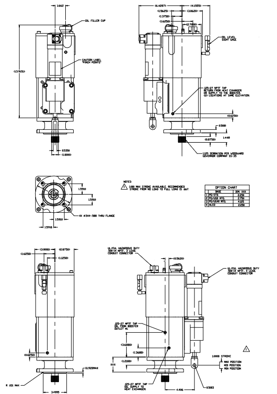
1. Actor: the core of mechanical action
(1) Core configuration and performance
Description of Key Parameters for Categories
Linear output of power cylinder: 16J (12ft lb), 23J (17ft lb), 39J (29ft lb), 79J (58ft lb)
Rotation output: 16N · m (12lb ft), 23N · m (17lb ft), 39N · m (29lb ft), 79N · m (58lb ft) linear stroke 25mm (1 inch), rotation stroke 30 °; Available travel/output is 2/3 of the maximum value
Hydraulic system oil pump: PG spur gear pump (low-speed version 0.812 inches thick, ≤ 1000rpm); High speed version 0.562 inches thick,>1000rpm)
Working pressure: Standard 896kPa (130psi), 58ft lb model 1655kPa (240psi) with built-in oil tank (2.5L/2.6 quarts), requires separate oil selection (refer to manual 25071)
Drive required speed: 200-1000rpm (bidirectional rotation, with check valve); Maximum 1500rpm (unidirectional, with plug)
Power: Maximum 375W (0.5hp), oil cooler needs to be selected for high speed or high ambient temperature
Position feedback non-contact Hall effect sensor outputs 3.6-4.4Vdc feedback voltage to the driver, achieving closed-loop control
Environmental adaptability working temperature: -29~+104 ℃ (-20~+220 ℉, limited by oil temperature)
Vibration resistance: Complies with WGC RV2 standard, maximum 7G parallel direction of drive shaft. Shell material: base/column made of cast iron, feedback shell made of aluminum alloy, internal parts made of surface hardened steel
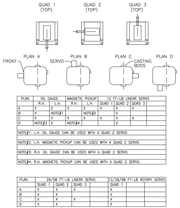
(2) Optional Features
Oil cooler: It needs to be installed when the actuator temperature exceeds 93 ℃ (200 ℉), and is divided into internal and external types;
Booster servo motor: using starting air to provide instant oil pressure, assisting equipment to start quickly;
Magnetic electric sensor (MPU): 1-2 optional, detects the speed of the prime mover through the drive shaft of the governor (cannot be used as a component of the overspeed protection system).
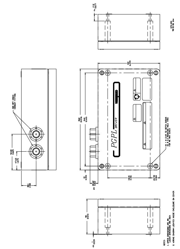
2. Driver: Electrical signal conversion core
(1) Core configuration and performance
Description of Key Parameters for Categories
Electrical signal input/output input: 18-32Vdc power supply, 0-200mA control signal (from electronic speed controller)
Output: 0-200mA drive signal (to actuator torque motor), 4-20mA position feedback signal (to indicator), built-in 210mA current limit to protect torque motor
The closed-loop control receives the 3.6-4.4Vdc signal from the actuator position sensor. After comparing the control signal, the output is adjusted and calibrated before leaving the factory. No field adjustment is required
Installation and environmental enclosure: cast aluminum box (cannot be directly installed on the prime mover)
Working temperature: -40~+70 ℃ (-40~+158 ℉)
Wiring: Use temperature resistant wires with a temperature rating of ≥ 90 ℃, comply with Class I, Zone 2 wiring standards, and require grounding to avoid electromagnetic interference (EMI). Refer to manual 50532
Wire length limit 16AWG (1.5mm ²): battery driver 457m, driver actuator 457m
14AWG (2.5mm ²): Battery driver 610m, driver actuator 610m shielded wire requires twisted pair, one end grounded and the other end suspended
Key requirements for installation and operation and maintenance
1. Installation specifications
(1) Mechanical installation
Attitude: The actuator should be installed vertically or nearly vertically to avoid force on the drive shaft (the actuator should not be placed on the drive shaft);
Transmission connection: The drive shaft should engage freely without any jamming, side load, or excessive axial clearance. The installation bolts should be evenly tightened to avoid shaking;
Connecting rod adjustment: Using 2/3 of the output stroke to achieve "no load full load" adjustment, the remaining stroke is distributed to both ends (ensuring that fuel can be cut off when turned off and maximum fuel can be provided at full load).
(2) Oil selection and maintenance
Oil requirements: viscosity 100-300SUS (at operating temperature), compatible with nitrile, polyacrylic acid, fluorocarbon sealing materials; Recommend using automotive/gas engine oil (such as SAE 10W30, 15W40) to avoid pollution;
Oil change cycle: Under normal working conditions, it should be replaced every year. In harsh environments (high temperature, high pollution), the cycle needs to be shortened; When changing the oil, it is necessary to drain it while it is hot, rinse it with a clean solvent (such as kerosene), and then add new oil.
(3) Electrical installation
Caution in hazardous areas: Do not plug or unplug connectors when live, and replacement parts must meet the requirements of Class I, Zone 2;
Grounding: Drivers and actuators need to be separately grounded to avoid parallel wiring with high voltage/high current wires and reduce EMI interference.
2. Initial operation and troubleshooting
(1) Initial operation steps
Confirm that the oil level is normal, there is no leakage, and the connecting rod is connected correctly;
Set the "low-speed start" mode on the electronic governor and prepare emergency shutdown measures;
Start the prime mover and gradually adjust the governor to the rated speed to ensure that the actuator operates linearly and without any jamming;
Verify closed-loop control: Change the control signal and check if the actuator output matches the feedback signal (10 ± 5mA corresponds to the minimum position, 175 ± 10mA corresponds to the maximum position).
(2) Common faults and solutions
Possible causes of symptoms and solutions
Unable to start/fuel rack does not open, actuator has no electrical signal, oil pump steering error, low oil level, connecting rod stuck. Check power and control signals; Confirm the direction of oil pump rotation; Oil replenishment; Repair the connecting rod
Slow action/delayed response, low speed (<200rpm), improper oil viscosity (too thin/too thick), worn oil pump, increasing speed or installing a boost servo; Replace the compatible oil; Repair/replace oil pump
Calibrate the connecting rod again due to the fluctuation of the prime mover (traveling/surging), nonlinearity of the connecting rod, oil contamination/foaming, and inaccurate parameters of the electronic governor; Change the oil; Adjust the parameters of the speed controller
Overheating of the actuator, high ambient temperature, driving speed exceeding 1500rpm, and installation of an oil cooler for oil oxidation; Reduce the rotational speed; Replace antioxidant oil
Principles of System Control and Safety Design
1. Control logic (closed-loop feedback)
Signal input: The electronic governor outputs a 0-200mA control signal to the driver based on the speed/load requirements;
Signal conversion: The driver converts the control signal into a 0-200mA driving current and sends it to the torque motor of the actuator;
Mechanical action: The torque motor drives the pilot valve, controls the flow of high-pressure oil to the power cylinder, and drives the output shaft action (adjusts the fuel/steam valve);
Feedback loop: The position sensor of the actuator converts the actual position into a 3.6-4.4Vdc voltage signal and feeds it back to the driver; The driver compares the control signal with the feedback signal, adjusts the output current until they match, and achieves precise positioning.
2. Security protection design
Power loss protection: When the control voltage is lost, the torque motor has no magnetic force, the spring pushes the pilot valve to release oil, and the power cylinder resets to the "minimum fuel" position to prevent the prime mover from overspeeding;
Overspeed independent protection: It is explicitly required that the prime mover be equipped with an overspeed shutdown device independent of the PGPL system (not dependent on the MPU of the actuator) to avoid loss of control caused by actuator failure;
Dangerous area protection: The shell is sealed and the wiring meets explosion-proof standards to prevent sparks from igniting dangerous gases.
Product Support and Services
1. Service Options
Quick replacement/exchange: Provide replacement parts of the same model within 24 hours to reduce downtime;
Fixed cost maintenance/renovation: Clearly define the maintenance cost in advance and restore it to a "near new product" state after maintenance;
Spare parts ordering: The model and serial number (indicated on the nameplate) of the actuator/driver must be provided to ensure that the spare parts match.
2. Compliance and Document Reference
Certification: UL (Class I, Zone 2), compliant with EU Machinery Directive 98/37/EC (without CE marking);
Related manuals: 25071 (hydraulic oil selection), 36692 (power cylinder specifications), 36693 (base specifications), 50532 (EMI control).
- YOKOGAWA
- Reliance
- ADVANCED
- SEW
- ProSoft
- WATLOW
- Kongsberg
- FANUC
- VSD
- DCS
- PLC
- man-machine
- Covid-19
- Energy and Gender
- Energy Access
- Renewable Integration
- Energy Subsidies
- Energy and Water
- Net zero emission
- Energy Security
- Critical Minerals
- A-B
- petroleum
- Mine scale
- Sewage treatment
- cement
- architecture
- Industrial information
- New energy
- Automobile market
- electricity
- Construction site
- HIMA
- ABB
- Rockwell
- Schneider Modicon
- Siemens
- xYCOM
- Yaskawa
- Woodward
- BOSCH Rexroth
- MOOG
- General Electric
- American NI
- Rolls-Royce
- CTI
- Honeywell
- EMERSON
- MAN
- GE
- TRICONEX
- Control Wave
- ALSTOM
- AMAT
- STUDER
- KONGSBERG
- MOTOROLA
- DANAHER MOTION
- Bentley
- Galil
- EATON
- MOLEX
- Triconex
- DEIF
- B&W
- ZYGO
- Aerotech
- DANFOSS
- KOLLMORGEN
- Beijer
- Endress+Hauser
- schneider
- Foxboro
- KB
- REXROTH
- YAMAHA
- Johnson
- Westinghouse
- WAGO
- TOSHIBA
- TEKTRONIX
- BENDER
- BMCM
- SMC
- HITACHI
- HIRSCHMANN
- XP POWER
- Baldor
- Meggitt
- SHINKAWA
- Other Brands
- UniOP
- KUKA
- IBA
- Beckhoff
-
Woodward 8272-796 - Real Power Sensor Module 115/230v-ac
-
Woodward 5463-873 - NetCon Output Module
-
Woodward 8271-567 - Load Sensor Module 120/208v-ac
-
Woodward Type UG-8 P/N 8522-300 EG - Governor R.P.M 1075-1650 With Motor Groschopp
-
WOODWARD 9905-971 REV J - LINKNET 16 CHANNEL DISCRETE INPUT MODULE
-
WOODWARD 8280-3014 - 723 PLUS DIGITAL CONTROL REV NEW
-
Woodward 505DE - Digital Control System
-
Woodward 5453-750 - Ethernet Interface FTM
-
Woodward 9907-018 Rev H - 2301A Load Sharing & Speed Control
-
WOODWARD 5420-1080 V4.3 - BOARD-PPA WITHBOX
-
Woodward b 8271-347SP - 2301 speed control
-
Woodward 9905-795 Rev B - Digital Synchronizer and Load Control
-
Woodward 9905-377 Rev. A - 2301A Load Sharing and Speed Control
-
WOODWARD 8272-582 - Generator speed control module
-
WOODWARD 9907-247 REV K - 828 DIGITAL CONTROL UNIT
-
WOODWARD 5466-353 REV C - NETCON MAIN CHASSIS TRANSCEIVER
-
Woodward Type UG-8 P/N 8524-708 - Governor 760-1560 Governor R.P.M
-
WOODWARD 9907-247 REV K - 828 DIGITAL CONTROL UNIT
-
WOODWARD 8440-1831 REV. H - EASYGEN3000 3200-5 - WITHOUT ACCESSORIES
-
WOODWARD 8444-1002 REV G - UMT1 MEASURING TRANSDUCERS
-
Woodward 5410-312C - Digital Marine Control Printed Circuit Board
-
Woodward 9905-799 REV F - Digital Synchronizer & Load Control , V#456
-
Woodward 9907-014 - 2301A for controller
-
Woodward Type UG-8 P/N B522-446 - Governor R.P.M 500-1200
-
WOODWARD 8272-221 REV.B - DIGITAL REFERENCE UNIT
-
Woodward 8901-037 - Booster Servomotor Single
-
WOODWARD 8444-1019 REV G - UMT 1 MEASURING TRANSDUCER
-
WOODWARD 1767-367 Z21 WK 0920702 - GOVERNOR MOTOR 2700 RPM KM 58-20 K 230V
-
WOODWARD 9905-972 Rev:G - LINKNET 6 CHANNEL 4-20mA OutPut
-
Woodward E8250-501 - Actuator Governor
-
WOODWARD 5466-258 REV M - SIMPLEX DISCRETE I/O MODULE
-
WOODWARD 5501-470 REV E - NETCON CPU MODULE
-
Woodward 8406-120 rev H - egcp-2 digital control
-
Woodward 8440-1799 - Easygen-350 Rev B
-
Woodward 8440-1878 - DSLC-2 Digital Synchronizer Load Control
-
Woodward 5464-843 - Cpu Processor Module
-
WOODWARD 8440-1409 Rev. J - MFR2 MDE Synchronization & Protection MSP
-
Woodward 9907-014 - controller
-
WOODWARD 9907-173 - LOAD SHARING MODULE 120V
-
WOODWARD 8440-1831 REV. K - EASYGEN 3200-5 - WITHOUT ACCESSORIES
-
Woodward 9905-969 - LinkNet Module LinkNet 6C 4-20ma in w/24v
-
Woodward 8520-498 - Governor Type UG-8 Governor R.P.M 850-1650
-
WOODWARD 5466-257 REV.-C - NETCON 5000 MODEL REMOTE TRANSCEIVER I/O MODULE
-
WOODWARD 8800 - 1001 REV-C - DSS-2, 2 CHANNEL DIGITAL SPEED SWITCH
-
WOODWARD 5501-467 REV. C - MICRONET SIMPLEX POWER SUPPLY
-
Woodward 8273-584 - Atlas-ii Digital Control
-
Woodward 8440-1019 b - spm-d10 synchronizing system
-
Woodward CSC3SUWA REV K - CSC3SUWA Controller
-
Woodward 5441-693 Rev B - Digital I/O Module
-
WOODWARD DPG-2201-002 REV.D - Governor Onan DIGITAL SPEED CONTROLLER
-
Woodward 9905-377 Rev. A - 2301A Load Sharing and Speed Control
-
WOODWARD 8440-1884K - GENERATOR CONTROLLER EASYGEN-2500-5 REV,K
-
WOODWARD 8404-1006 - Industrial Component
-
WOODWARD 5437-1118 - PROTECHTPS MODULE Relay Bulkhead Panel
-
Woodward 8440 1801 Rev C - Easygen-350-50B/X Genset Control Engine Generator 24VDC
-
WOODWARD 5466-348 - MODULE
-
Woodward 9905-799 REV F - Digital Synchronizer & Load Control , V#456
-
Woodward 9907-018 - 2301A Load Sharing & Speed Control Rev H
-
Woodward GM9412H918-R2 1766-039 REV E - Cruise Control Motor
-
5466-258 WoodWard - 48 Input 24 Output Discrete I/O, (UPP)
-
WOODWARD 5484-877 - PM MOTOR 24VDC 15RPM
-
Woodward 8272-221 B - Digital Reference Unit
-
Woodward 9905-796 - Digital Synchronizer And Load Control (Rev. H)
-
WOODWARD 5441-645 REV.G - 10AMP RELAY INTERFACE 11459968
-
Woodward 9907-207 - 721 Digital Control 88-132VAC
-
WOODWARD 8272-582 - APM MOTOR CONTROL AC/DC 100~220V
-
Woodward 5464-843 - Cpu Processor Module
-
Woodward 9905-001 L - SPM-A Synchronizer 115/230V 50/60Hz 10W
-
Seg Power Protection PCK4 P/N 8445 1006 A / PCKR-MW - Protection Relay 24VDC
-
Woodward 8405-062 - Actuator
-
Woodward 5464-738 - Industrial Control System
-
Woodward CSC3HUWB - controller
-
Woodward 8272-517 - PM Motor Control 220vac
-
Woodward 8272-582 - APM Motor Control
-
Woodward LR20025 MFR1375M MFR 1 - Controlling
-
Woodward 9905-392 - Proact Driver Model III
-
WOODWARD 8250-774 - ACTUATOR/GOVERNOR
-
Woodward 505DE - Digital Control System
-
Woodward 8280-303 D - 721 Digital Control Rev.G 2.0 AMP 28 VDC
-
WOODWARD DPG-2201-002 REV NEW - DIGITAL CONTROLLER
-
WOODWARD 8272-286 - 2301A LOAD SHARING & SPEED CONTROL MODULE
-
WOODWARD 8440-1884 REV M - GENSET CONTROLLER EASYGEN-2500-5/P1
-
Woodward 9905-797 Rev. M - Digital Sync And Charge Control
-
W0ODWARD ART-01681 - IDS Communicator Control Box
-
Woodward 8273-584 - Digital Control Unit ATLAS-II REV: A 18-32VDC, 60W
-
WOODWARD 5501-470 REV E - NETCON CPU MODULE
-
Woodward 1752 1752-227 - Revision D FireFly Current Load input Engine Control
-
Woodward 8440-1877 - MSLC-2-5 Control
-
Woodward 8271468 - Generator Loading Control (Rev. D)
-
Woodward 9905-387 - Pro Act Driver Model lll (Rev. F)
-
Woodward 9905-363 - Sincronizzatore Digitale E Controllo Carico
-
WOODWARD 8272-583 - APM MOTOR CONTROL
-
WOODWARD EGCP-2 - Digital Generator Control Panel 4-20MA 5V 500HZ
-
Woodward 9905-392 - Proact Driver Model III
-
Woodward 9905-392 - Proact Driver Model III
-
Woodward 8270-007 - Load Signal Control
-
Woodward 8271-651 - Digital Speed Reference
-
WOODWARD 8440-2219 - EASYGEN-2500-5-P1-K49 GENSET CONTROLLER
-
Woodward D8271-394 - 2301 Load Sharing And Speed Control Module 20-40v-dc
-
Woodward 8200-1504 Rev:E - Peak200 Steam Turbine Control Front Panel Mount HVAC
-
WOODWARD 8444-1022 REV F - UMT 1 MEASURING TRANSDUCER
-
WOODWARD 8440-1923 A - EASYGEN-3200-5 CONTROLLER
-
WOODWARD 9907-014 - 2301A controller
-
Woodward 8272-583 - Amp Motor Control DC24V
-
Woodward 9907-147 REV N - ProTech 203 Overspeed Protection System
-
Woodward 8270-417 - 2301 speed sensor
-
Woodward 8272-583 - Amp Motor Control DC24V
-
Woodward 8934-658 - Repair Kit UG8D Governor
-
Woodward 5437-281 - analog module
-
Woodward 8440-2177 A - SPM-D2-10 Digital Synchronising Controller
-
SA-4478 EPS1000 - Speed Switch
-
Woodward 9907-014 Rev: J - 2301A Speed Control
-
Woodward 9907-026 Rev C - Load Sharing Module
-
Woodward B8271-464 H B8271464 - 2301 Speed Control
-
WOODWARD 8440-1667 REV C - SPM-D10 SYNCRONIZING UNIT
-
Woodward 8440-2082 - EASYGEN-3200XT-P1 Engine Generator Control
-
Woodward 8406-120 rev H - egcp-2 digital control
-
WOODWARD SPM-D - SYNCHRONIZING SYSTEM
-
Woodward 8271-651 - Digital Speed Reference
-
WOODWARD 8444-1074 A - MODULE
-
WOODWARD 8440-2050 Rev B - EASYGEN-3200-5 CONTROLLER
-
Woodward 8440-1613 REV E - GCP30 Genset Control Package
-
Woodward 9907-018 - Load Sharing & Speed Controller Rev H 90-240VAC
-
Woodward 5466-315 - module
-
Woodward 9905-204 Rev N - SPM-A synchronizer
-
Woodward XG2 - Protection relay
-
WOODWARD 9907-175 LOAD SHARING MODULE REV A - Load Sharing Module
-
Woodward 9907-166 REV: N - 505E Turbine Control 110V AC/DC

K-JIANG

Add: Jimei North Road, Jimei District, Xiamen, Fujian, China
Tell:+86-15305925923