
K-WANG


Lennox ZHA series heat pump complete set (507257-01b)
Electrical safety: power-off operation is a prerequisite - the power supply of the unit must be turned off during any maintenance to avoid the risk of electric shock or explosion; Before powering on, it is necessary to confirm that the voltage meets the range indicated on the nameplate, and the three-phase power supply must ensure phase balance (especially for models with frequency converters).
Lennox ZHA series heat pump complete set (507257-01b)
Core Security and Basic Instructions
1. Safety warning (highest priority)
Operation qualification: It is explicitly required that installation, commissioning, and maintenance must be carried out by licensed HVAC professionals or equivalent service organizations. Improper operation may result in property damage, personal injury, or even death.
Electrical safety: power-off operation is a prerequisite - the power supply of the unit must be turned off during any maintenance to avoid the risk of electric shock or explosion; Before powering on, it is necessary to confirm that the voltage meets the range indicated on the nameplate, and the three-phase power supply must ensure phase balance (especially for models with frequency converters).
Refrigerant compliance: In accordance with the 1990 Clean Air Act, intentional discharge of CFCs and HCFCs refrigerants is prohibited, and compliant methods such as recycling, regeneration, or reuse must be adopted. Violation may result in fines or imprisonment.
Roof protection: The unit contains refrigerant and engine oil, and some rubber roof materials may absorb engine oil, causing expansion and leakage. During installation and maintenance, the roof surface should be protected to avoid direct contact.
2. Basic parameters and applicable scope
Unit specifications: Cooling capacity covering 7.5-10 tons, optional distribution heating module; Some models support air supply frequency converters, which can automatically adjust the fan speed according to the load during cooling (low load low speed, high load high speed). When the fan runs alone, it is at low speed, and when heating, it is at high speed.
Installation restrictions: It is prohibited to use the unit as temporary heating/cooling equipment during the construction phase. Low temperature return air, harmful gases, or clogged filter elements can damage the unit; If used in violation of regulations, specific conditions must be met (such as thermostat control, installation of pre filters, etc.), otherwise the warranty will be invalidated.
Core installation process and technical requirements
1. Preliminary preparation: Packaging inspection and installation clearance
Packing list: A single package contains one assembled unit. Upon receipt, it is necessary to immediately inspect for transportation damage. If there are any issues, contact the final carrier.
Installation clearance (key dimensions): It is necessary to strictly follow the operation and operation clearance around the unit to ensure heat dissipation and maintenance space, as shown in the following table:
|Gap Type | A (inches/millimeters) | B (inches/millimeters) | C (inches/millimeters) | D (inches/millimeters) | Top Gap|
|Maintenance gap | 36 (914) | 36 (914) | 60 (1524) | 36 (914) | unobstructed|
|Minimum operating clearance | 36 (914) | 36 (914) | 60 (1524) | 36 (914) | unobstructed|
2. Unit support and fixation
According to the direction of air supply (downward air supply/horizontal air supply), the support requirements vary, and the core is to ensure that the unit is level, leak proof, and corrosion-resistant:
Down air supply application: can only be installed on non flammable surfaces; If installed on flammable surfaces, it is necessary to use Z1CURB roof installation frame, which should be horizontal (with an error of ≤ 1/16 inch per linear foot, or ≤ 5 millimeters per meter) and sealed and fixed to the roof.
Horizontal air supply application: The top of the support platform should be about 4 inches (102 millimeters) above the ground to avoid water accumulation; The supporting structure needs to be built along the four sides of the unit base, made of steel or anti-corrosion treated wood, with a recommended minimum height of 14 inches (356 millimeters) to prevent moisture from entering.
General requirements: The air duct should be connected to the roof frame rather than the unit itself, and the return air static pressure box should be installed before the unit is in place.
3. Lifting and positioning (to avoid structural damage)
Lifting parameters: The maximum weight of the unit (including all accessories) is 1270 pounds (576 kilograms), and 4 cables need to be used to connect the base track holes, along with the "H-shaped lifting device" provided on site to prevent deformation of the unit.
Key steps:
Remove the wooden base protection board before lifting;
Connect the two holes at each corner of the cable base to ensure that all panels are installed in place before hoisting;
After partially lifting the unit, remove 5 L-shaped brackets that fix the protective substrate;
The new roof curb (length 89-3/8 inches) requires the removal of 3 positioning brackets, while the old curb (length 81-3/4 inches) needs to be positioned with positioning brackets as shown in the diagram.
4. Connection between condensate discharge and air duct
Condensed water drainage: The unit is equipped with a 1-inch NPT drainage interface, and the drainage pan is made of fiberglass reinforced engineering plastic. When connecting, the pipe joint needs to be manually tightened and then an additional 1/4 turn should be added to avoid damage caused by excessive force; A trap must be installed, and the drainage pipeline must have a slope of 1 inch (25 millimeters) every 10 feet (3 meters), in accordance with local drainage regulations.
Air duct requirements: Outdoor air ducts, joints, and roof/wall openings need to be insulated and waterproofed (using waterproof boards and sealant); Air ducts passing through non air conditioned areas must be insulated; Drilling holes in the base of the unit is prohibited in the application of down air supply to prevent roof leakage.
5. Electrical connection (including special model requirements)
Power wiring:
The 230/460/575V models are factory pre wired, and for 208V power supply, all pink (230V) wires of the control power transformers need to be disconnected, reconnected, and the exposed 230V wire ends wrapped;
The power cord needs to be introduced from the bottom entry area and connected to the L1, L2, and L3 terminals of TB13 in the control box. If there is an S48 isolation switch (pre installed in the factory), it needs to be connected according to the wiring diagram.
Three phase voltage balance (with frequency converter model): The frequency converter relies on a balanced three-phase power supply. If the power supply is unbalanced, a higher current level frequency converter needs to be replaced (refer to Table 1:5HP → 7.5HP → 10HP gradually upgraded), otherwise it will reduce the reliability of electrical components.
Thermostat installation:
Location: Vertically installed on a 2 × 4 inch junction box or non-conductive surface, with a height of approximately 5 feet (1524 millimeters), avoiding areas such as air vents, direct sunlight, and electrical radiation;
Wiring: Use 18AWG wire, and non high voltage rated thermoelectric wires should be kept away from the power line and secured with a wire tie in the lower left corner of the control area.
Run debugging and parameter setting
1. Pre startup inspection (mandatory steps)
Confirm that the installation complies with the instructions and local regulations, and that all electrical wiring (factory+on-site) is not loose;
Check that there is no friction in the refrigerant pipeline (avoid contact with the cabinet or other pipelines);
Confirm that the power supply voltage is within the range indicated on the nameplate. If it does not meet the requirements, contact the power company for adjustment;
Install the filter element and ensure that the thermostat has no heating, cooling, or fan requirements before powering on.
2. Fan operation and adjustment
Phase correction of three-phase compressor: The factory has pre-set the phase (L1 red, L2 yellow, L3 blue), and after starting up, it is necessary to observe the suction and exhaust pressure and the direction of the fan. If there is no pressure difference or the direction is incorrect, the power supply needs to be disconnected and any two on-site connections on the incoming side of K3, TB2 or F4 need to be replaced (it is forbidden to replace the fan contactor or compressor connection).
Fan speed and CFM calculation:
Non variable frequency models: Run the fan when there is no cooling demand, measure the fan shaft speed and the external static pressure (between the supply and return air) of the unit, and refer to the fan data sheet on pages 10-12 to determine the CFM;
Variable frequency model: High voltage switches S4 and S7 need to be disconnected to trigger Y1/Y2 and run the fan at high speed, then measure and calculate;
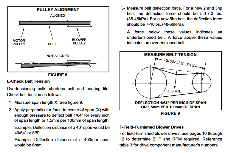
Speed adjustment: It is achieved through the motor pulley. Clockwise rotation of the adjustable pulley increases CFM, while counterclockwise rotation reduces CFM. The minimum/maximum rotation number of the belt should be observed (0-5 turns for A-type belt, 1-6 turns for B-type belt, and there is no minimum rotation limit for B-type belt pulleys over 6 inches).
Belt tension adjustment: The new belt needs to be re tensioned after running for 24-48 hours. The tension standard is: 2-3HP belt deflection force 5.0-7.0 pounds (35-48kPa), 5HP belt 7-10 pounds (48-69kPa), deflection amount of 1/64 inch per inch span (1.5 millimeters per 100 millimeters span).
3. Heating and cooling start-up
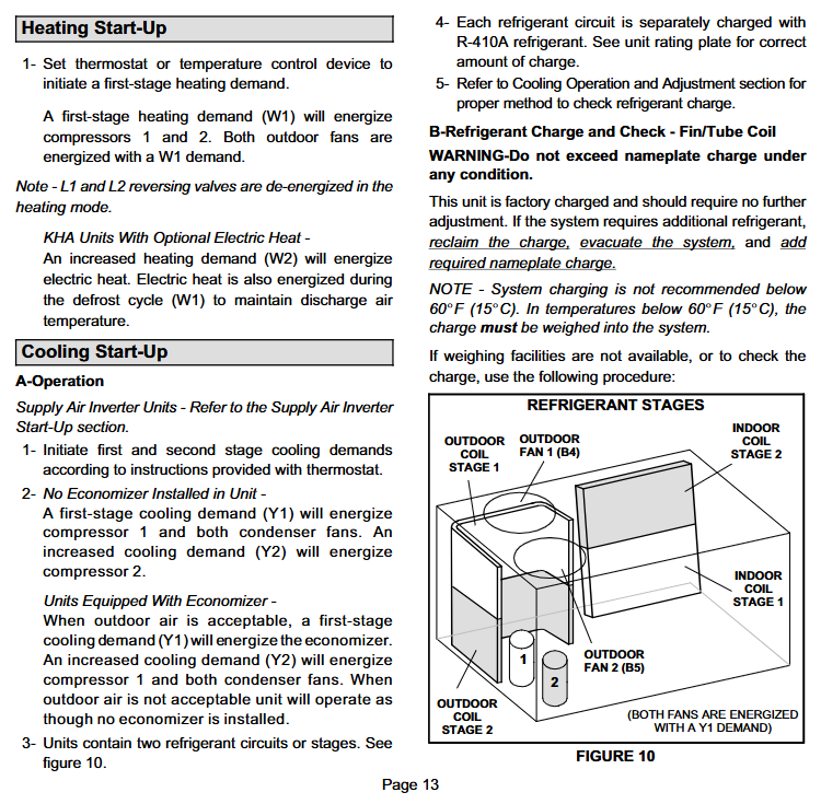
Heating start: Set the thermostat to level one heating (W1), triggering the operation of compressors 1 and 2 and the outdoor fan (power off L1 and L2 reversing valves in heating mode); If there is optional electric heating, the secondary heating (W2) will activate the electric heating, and the electric heating will also be activated during the defrosting cycle (W1) to maintain the supply air temperature.
Refrigeration start:
Model without energy-saving device: compressor 1 and two condenser fans are activated for primary refrigeration (Y1), and compressor 2 is activated for secondary refrigeration (Y2);
Model with energy-saving device: When the outdoor air meets the conditions, Y1 activates the energy-saving device first, and Y2 activates compressor 1 and fan when the load increases;
Refrigerant inspection: The unit factory pre charges R-410A without the need for additional charging; If it is necessary to supplement, the original refrigerant should be recovered and vacuumed first, and then filled according to the amount indicated on the nameplate (weighed and filled below 60 ° F/15 ° C). It is forbidden to exceed the nameplate filling amount.
4. Defrost control (core function of heat pump)
Defrost triggering and termination: triggered by the liquid tube temperature (≤ 35 ° F/1.7 ° C), the defrost controller (CMC1) starts defrosting after 60 minutes (100269-02 board) or 90 minutes (100269-04 board) of cumulative heating operation by default, lasting for 14 minutes; If the steam pressure reaches 450 PSI (3103 kPa), the defrost pressure switch will prematurely terminate defrosting.
Defrost time adjustment: The defrost interval can be set to 30/60/90 minutes through the jumper on the CMC board. The factory defaults to 60 minutes, and when there is no jumper, it defaults to 90 minutes.
Diagnostic LED: The defrost board has 2 LED lights, and the status is determined by flashing mode (normal operation: synchronous flashing; no power/board fault: all off; board fault: all on; anti short cycle lock: alternate slow flashing).
Maintenance and Service Standards
1. Regular maintenance cycle and content
Annual inspection (performed by professionals):
Filter element: The unit comes with a 20 × 24 × 2 inch temporary filter element at the factory. Before the building is put into use, it needs to be replaced with a compliant filter element (which requires U.L.C certification in Canada). It will be inspected monthly and replaced when it is dirty; When replacing, open the access door of the filter element on the back of the unit, lift the filter element stopper to remove it, and pay attention to the airflow direction markings.
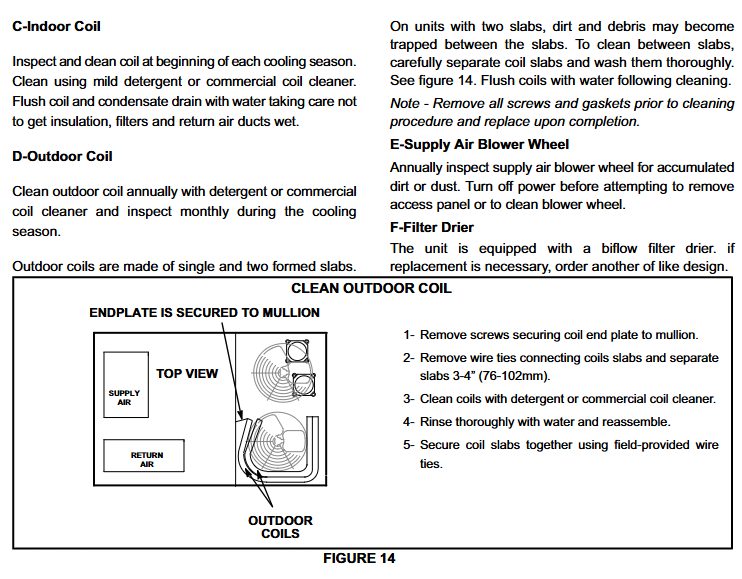
Coil cleaning: Clean indoor coils before the start of the cooling season (using neutral or commercial coil cleaners, and avoid soaking insulation materials, filter elements, and return air ducts during flushing); The outdoor coil is cleaned annually, and the double slab coil needs to remove screws and washers, separate 3-4 inches, clean the interlayer, and then reassemble.
Fan wheel: Check the dust accumulation on the supply fan wheel every year, and remove the maintenance door for cleaning after power failure.
Maintenance free components: All motors are pre lubricated by the factory and do not require subsequent refueling; If the bidirectional drying filter needs to be replaced, the same model of product should be selected.
2. Precautions for troubleshooting
During maintenance, all wires should be marked before disconnecting to avoid wiring errors;
Refer to the "Defrost Control Board Diagnostic LED" and "Normal Operating Pressure Gauge" (Table 4-6, covering the suction and exhaust pressure range at outdoor temperatures of 65-115 ° F) to determine if the compressor, fan, and other components are functioning properly;
If the unit is used for temporary temperature control during construction, it must meet the conditions of "thermostat control, installation of pre filter, return air temperature 13-27 ° C", otherwise the warranty will be invalid, and the heat exchanger, air duct, filter element and other components must be thoroughly cleaned after construction is completed.
- YOKOGAWA
- Reliance
- ADVANCED
- SEW
- ProSoft
- WATLOW
- Kongsberg
- FANUC
- VSD
- DCS
- PLC
- man-machine
- Covid-19
- Energy and Gender
- Energy Access
- Renewable Integration
- Energy Subsidies
- Energy and Water
- Net zero emission
- Energy Security
- Critical Minerals
- A-B
- petroleum
- Mine scale
- Sewage treatment
- cement
- architecture
- Industrial information
- New energy
- Automobile market
- electricity
- Construction site
- HIMA
- ABB
- Rockwell
- Schneider Modicon
- Siemens
- xYCOM
- Yaskawa
- Woodward
- BOSCH Rexroth
- MOOG
- General Electric
- American NI
- Rolls-Royce
- CTI
- Honeywell
- EMERSON
- MAN
- GE
- TRICONEX
- Control Wave
- ALSTOM
- AMAT
- STUDER
- KONGSBERG
- MOTOROLA
- DANAHER MOTION
- Bentley
- Galil
- EATON
- MOLEX
- Triconex
- DEIF
- B&W
- ZYGO
- Aerotech
- DANFOSS
- KOLLMORGEN
- Beijer
- Endress+Hauser
- schneider
- Foxboro
- KB
- REXROTH
- YAMAHA
- Johnson
- Westinghouse
- WAGO
- TOSHIBA
- TEKTRONIX
- BENDER
- BMCM
- SMC
- HITACHI
- HIRSCHMANN
- XP POWER
- Baldor
- Meggitt
- SHINKAWA
- Other Brands
- UniOP
- KUKA
- IBA
- Beckhoff
- ADLINK
-
ADLINK HPCI-14S12U - Industrial Control Backplane 12PCI Backplane PCI-14S Passive Backplane
-
ADLINK PCIe-GIE74C - image acquisition card 4-CH GigE Vision PoE+ Frame Grabber
-
ADLINK PCI-8164 - control card 4-Axis Advanced Motion Controller Board
-
ADLINK PCIe-U304 - 4 Port USB3 PCIe Frame Grabbers USB Screw Hole Card
-
ADLINK PCI-9112 - Multi-Function Data Acquisition Card DAQ Card
-
ADLINK PCI-7432 - 51-12013-0A50 4-CH Isolated Numérique I/O PCI Cartes Digital I/O Card
-
ADLINK PCA-6106P3-0C1 REV.C1 - backplane 6-Slot Passive Backplane Board
-
ADLINK PCI-7224 - 24-CH Opto-Isolated Digital I/O PCI Board
-
ADLINK CPCI-7433R(G) - Digital Input Board Rear I/O CompactPCI Card
-
ADLINK EBP-13E4 - 51-46703-0A30 Industrial PC Backplane Passive Backplane
-
ADLINK PCIE-HDV62 - Image acquisition card High Definition Video Frame Grabber
-
ADLINK EBP-13E4 - 51-46703-0A30 Industrial Backplane Board Passive Backplane
-
ADLINK 90111-B1 / CPCI-6770 - PCB CPU MODULE CompactPCI Single Board Computer
-
ADLINK PCI-7248 - DATA ACQUISITION PCI CARD 48-CH Parallel Digital I/O Board
-
ADLINK PCI-7230 - 51-12003-0a50 board PCI7230 32-CH Isolated Digital I/O Card
-
ADLINK PCI2A000CB - 51-20000-0B30 Multi-Function DAQ Card Baseboard
-
ADLINK PCI-8134-005 - 4-Axis Motion Controller Card
-
ADLINK PCI-7224 - 24-CH Opto-Isolated Digital I/O PCI Card
-
ADLINK PCI-7434 - 64-CH Isolated Digital Output Card
-
ADLINK PCI-8132 - motion control card 2-Axis Servo & Stepper Controller
-
ADLINK PCI-8134 - Motion Controller PCI Card 4-Axis Controller Board
-
ADLINK PCI-8164 - Motion Control Card 51-12406-0A40 4-Axis Controller
-
ADLINK 51-12001-0C20 - Circuit Board Data Acquisition Interface Module Hardware
-
ADLINK NuPR0-840 - industrial control motherboard Full-Size PICMG CPU Board
-
ADLINK PCI-7444 - 51-12023-0A10 card 128-CH Isolated Digital Output Board
-
ADLINK PCI-1612B - data acquisition card 4-Port RS-232/422/485 Serial Communication Card
-
ADLINK PCI-6208V 009 - 8/16-CH 16-Bit Analog Output Cards PCB-I-E-482=6BX3
-
ADLINK NUPRO-935A/LV - industrial control motherboard Full-Size PICMG SBC Board
-
ADLINK PCI-9114DG - Multi-Function DAQ Card Data Acquisition PCI Card
-
ADLINK ACL-7130 - Data acquisition card Isolated Digital I/O Board
-
ADLINK ABX-6300D-4E1-BP - board ABX6300D4E1BP Video Interface Expansion Card
-
ADLINK CPCI-6940 - CPCI-6940/D1539/M16-0(EA)-000E 6U CompactPCI Processor Board
-
ADLINK NuPRO-760 - industrial control motherboard Half-Size PICMG SBC CPU Board
-
ADLINK IMB-M42H (G)-0020 - industrial control motherboard LGA1155 Micro-ATX Mainboard
-
ADLINK RTV-24 / PCI-MP4S - 51-12519-1C30 4-Channel Real Time Video Capture Board
-
ADLINK PCI-8134 - 4-Axis Servo & Stepper Motion Controller Card
-
ADLINK MXC-6101D - V.PC000.002.ST.00 Box PC Configurable Embedded Computer
-
ADLINK PCI-8134A - 51-12421-0A10 Motion Control Card 4-Axis Controller Card
-
ADLINK DIN-100S / DIN-100SA1 - Technology SCSI-II TB 100-PIN Terminal Block Board
-
ADLINK DIN-812M001 / DIN812M001 - 51-14034-0A1 51140340A1 Terminal Module Breakout Interface
-
ADLINK PCI-8164 - Servo motion control 4-Axis Advanced Controller Card
-
ADLINK PCIe-GIE64 - Acquisition card GigE Vision PoE+ Frame Grabber
-
ADLINK M-302 - Industrial control motherboard ATX PC Board Mainboard
-
ADLINK PCI-8134 - Motion Controller PCI Card 4-Axis Controller Board
-
ADLINK PCI-RTV24 - Image capture card Analog Video Frame Grabber
-
ADLINK PCI-8102 - Motion control card 2-Axis Servo & Stepper Controller Board
-
ADLINK PCI-9112 REV.B1 - Card Multi-Function Data Acquisition Card
-
ADLINK HSI-DI32-M-N / HSL-TB32-M-DIN - Discrete I/O MODULE Distributed Automation Module System
-
ADLINK PCI-7296 - IO card REV.A3 96-CH Parallel Digital I/O Card
-
ADLINK DIN-814P-A4 / 814Y - terminal board Motion Control Interface Block
-
ADLINK DIN-814P-A4 - 51-14056-0A10 PCB-I-E-2736=ZA01 Screw Terminal Board Breakout
-
ADLINK M-322 - motherboard Industrial Control Computer Mainboard
-
ADLINK NUPRO-406 REV:B1 - industrial control motherboard Full-Size PICMG CPU Board
-
ADLINK AMP-204C - card DSP-Based 4-Axis Advanced Pulse-Train Controller
-
ADLINK HPCI14S REV.B1 - industrial computer baseboard 14-Slot Passive Backplane
-
ADLINK PCI-7250 - 8-CH Relay Output & 8-CH Isolated DI PCI Card
-
ADLINK EBP-13E2 - baseplate Passive Backplane Industrial Computer Chassis Board
-
ADLINK LPCI-3488A - PCI-GPIB card 51-12801-0A30 acquisition card IEEE-488 Interface Board
-
ADLINK PCI-6216V-GL - 51-12201-0C30 16-CH 16-Bit Voltage Analog Output Card
-
ADLINK ACL-8454 - 16-CH Isolated Digital I/O & 4-CH Counter Card
-
ADLINK HPCI-9S7U - backplane Passive Backplane Compatible with NuPRO-A301 852 841 842
-
ADLINK DAQ-2010-007 - Simultaneous-Sampling Multi-Function Data Acquisition Card
-
ADLINK MP-C154 - 51-64205-0A10 Motion Control Card 4-Axis Controller Board
-
ADLINK MXE-202/mSSD16B/WiFi-BT - Matrix Rugged I/O Platform Embedded Fanless Computer
-
ADLINK CM-920-R-17 - PC/104-Plus Single Board Computer Module Intel Celeron M
-
ADLINK PCI-7250 NSMP - 8-CH Relay Output & 8-CH Isolated DI Card
-
ADLINK PCI-8164 - 4-Axis Motion Controller PCI Card W/ Cable and Breakout Box
-
ADLINK EMX-100 - Ethernet-based 4-axis Motion Controllers Distributed Motion Module
-
ADLINK PCI-8134A - Press control card 4-Axis Motion Controller Board
-
ADLINK M-845EG REV:3.2 - industrial motherboard Pentium 4 Socket 478 Micro-ATX
-
ADLINK PCI-9114A Rev A2 DG - card High-Resolution Multi-Function Data Acquisition Board
-
ADLINK IEC-915GV - REV 1.1 Industrial motherboard Socket 478 CPU Board
-
ADLINK PCI-9111DG(G) - Data Acquisition Card Multi-Function DAQ Card
-
ADLINK HPCI-15S10 REV:B2 - Industrial computer base plate Passive Backplane Board
-
ADLINK NuPR0-840 / NuPR0-840DV - industrial control motherboard Full-size PICMG CPU Board
-
ADLINK RTV-24 / PCI-MP4S - 51-12519-1C30 4-Channel Real Time Video Capture Board
-
ADLINK NUPRO-780 - industrial control motherboard Pentium III Single Board Computer
-
ADLINK PCI-7296 - 0050 card 96-CH Opto-Isolated Parallel DIO Card Set
-
ADLINK NUPRO-780 - industrial control motherboard PICMG Full-Size SBC
-
ADLINK PCI-7248 - 51-12006-0A3 002 Pci 7248 48-CH Parallel Digital I/O Card
-
ADLINK cPCI-6626 - 6U CompactPCI 2.0 Blades i7-2710QE PCB-I-E-2570=9N41
-
ADLINK MXC-6322D(G) - Industrial Fanless Computer
-
ADLINK cPCI-8168-004 - CompactPci NulPC Motion Control Board 51-36402-0A3
-
ADLINK CPCI-7300[G] - COMPACTPCI Digital I/O Card Data Acquisition
-
ADLINK CPCI-6626/2710/M4G - COMPACTPCI COMPUTER BOARD
-
ADLINK cPCI-8168-009 - cPCI NulPC Motion Control Board
-
ADLINK cPCI-6626/2710/M4G - VME CPU Board Computer Board
-
ADLINK CPCI-R6200(G)-0040 - COMPACTPCI CONTROL BOARD
-
ADLINK CPCI-3840/PM18/M1G(G)-3650 - COMPACTPCI CPU Module Single Board Computer
-
ADLINK cPCI-7248 - 48-CH Opto-22 Compatible Digital I/O Module
-
ADLINK DLAP-211-JNX - NVIDIA Jetson Xavier NX Edge AI Inference Platform
-
ADLINK cPCI-3544 - Series 4-Port RS-422/485 Isolated Serial Communications Card
-
ADLINK CM1-86DX3 - PC/104 SBC Stanley Vortex86DX3 CPU 2GB Ram
-
ADLINK DLAP-211-JNX - NVIDIA Jetson Xavier NX Edge AI Inference Platform
-
ADLINK cPCI-3544 - Series 4-Port RS-422/485 Isolated Serial Communications Card
-
ADLINK CM1-86DX3 - PC/104 SBC Stanley Vortex86DX3 CPU 2GB Ram
-
ADLINK PCI-7433 - switch value acquisition card Isolated Digital Input Card
-
ADLINK PCI-9112 - 51-12252-0D20 Multi-Function Data Acquisition Card
-
ADLINK NUPRO-A301 REV:1.4 - industrial control motherboard PICMG Full-Size SBC
-
ADLINK 51-18502-0A10 - Frame Grabber Image Acquisition Interface Card
-
ADLINK PCI-7296 - 51-12009-0A50 PCB-I-E-925=6DX1 96-CH Parallel Digital I/O Board
-
ADLINK PCI-8132 GP A2 - Motion Control Card 2-Axis Servo & Stepper Controller
-
ADLINK PCI-7442 - switch quantity card data acquisition card 64-CH Isolated Card
-
ADLINK HPX-13S4 - baseboard PICMG 1.3 Passive Backplane Chassis Baseplate
-
ADLINK NuPRO-590 / NTC-567-ZM-F36 - Single Board Computer PCB-I-E-1853=9L21 Half-Size SBC
-
ADLINK PCIe-8332 - 16-axis plate Motion Control Hardware Card
-
ADLINK NuPRO-775 REV.B1 - motherboard Pentium 4 Full-Size PICMG SBC
-
ADLINK PXI-3920 - Embedded Controller 3U PXI cPCI System Intelligence Board
-
ADLINK PCI-8134 - driver card motion control card 4-Axis Controller Board
-
ADLINK HSL-DI32-M-N-011 / HSL-TB32-M-DIN - Digital Input & Base Module PLC Distributed I/O System
-
ADLINK PCI-6216V-206 / PCI-208V 009 - 16 CH 16bit analog output card
-
ADLINK NuPro-E330 - 51-41805-0A20 PCB Single Board Computer Host Board
-
ADLINK PCI-1622C - Card 8-Port RS-232/422/485 PCI Serial Communication Board
-
ADLINK PCIe-7432 - 51-18402-0A10 Carte PCIe Avec Plage D'Entrée Élevée Isolated DIO Card
-
ADLINK PCI-7250 - PCI Acquisition Card 8-CH Relay Output Isolated DI Card
-
ADLINK PCI-7230 - 32-CH Isolated Digital I/O Card
-
ADLINK PCI-8164 - PCB 4-Axis Motion Controller Card
-
ADLINK PCI-7854 - Collection card High-Speed Link Distributed Motion Controller
-
ADLINK NuPRO-935A/LV - industrial control computer motherboard Full-Size PICMG SBC
-
ADLINK IMB-M40H - motherboard IH61-AA4 1155 LGA1155 Micro-ATX Mainboard
-
ADLINK PCI-7248 - Linhua 51-12006-0A40 48-CH Parallel Digital I/O Card
-
ADLINK HPCI-14S12U - Linhua industrial computer baseboard Passive Backplane
-
ADLINK PCI-8132 Rev.A2 - 2-Axis Servo & Stepper Motion Controller Card
-
ADLINK ACL-8111 - ISA card Multi-Function DAQ Card
-
ADLINK ACL-8111 - ISA card Multi-Function Data Acquisition Board
-
ADLINK PCI-7200 REV.A3 - Digital I/O card 12MB/s High-Speed Parallel Digital I/O
-
ADLINK PCI-7296 REV.A3 - 96-CH High-Density Opto-Isolated DIO Card
-
ADLINK PCI-7434 - 64-CH Isolated Digital Output Card

K-JIANG

Add: Jimei North Road, Jimei District, Xiamen, Fujian, China
Tell:+86-15305925923