
K-WANG


Woodward 723 Generator Controller
Woodward 723 Generator Controller
Application and Overview
The Woodward 723 generator controller is suitable for various generator application scenarios, including auxiliary generators and diesel electric propulsion in ship systems, as well as islanding mode operation and basic load operation on infinite power grids in power plant systems. It has closed-loop speed control function, equipped with torsion filter and notch (band stop) filter, which can alleviate low-frequency oscillation problems caused by engine, generator inertia and flexible coupling. The controller has three operating modes, namely droop control based on 4-20mA megawatt sensor input or actuator position, synchronous load distribution with soft loading/unloading and automatic generator circuit breaker opening command after engine unloading, and megawatt control with soft loading/unloading and automatic generator circuit breaker opening command after engine unloading.
Hardware specifications
Model and output: The models include 8280-500, 8280-501, 8280-502, and 8280-503, which correspond to different voltages and output types. For example, 8280-500 is a high-voltage control with an actuator output of 0-200mA.
Power supply and power consumption: The power supply has 18-40Vdc (nominal 24 or 32Vdc) and 90-150Vdc (nominal 125Vdc), with a nominal power consumption of 40W.
input/output
Speed signal input: The frequency range of the magneto electric sensor is 400-15000Hz, and the proximity switch is 7.5-1000Hz.
Digital input: 8, 8mA at 24Vdc.
Analog inputs: 4, 4-20mA or 1-5VDC.
Analog output: 3, of which 2 are 4-20mA or 0-1mA (connected to instruments or computers), and 1 is 20-160mA or 4-20mA.
Output of actuator: 1, 20-160mA or 4-20mA.
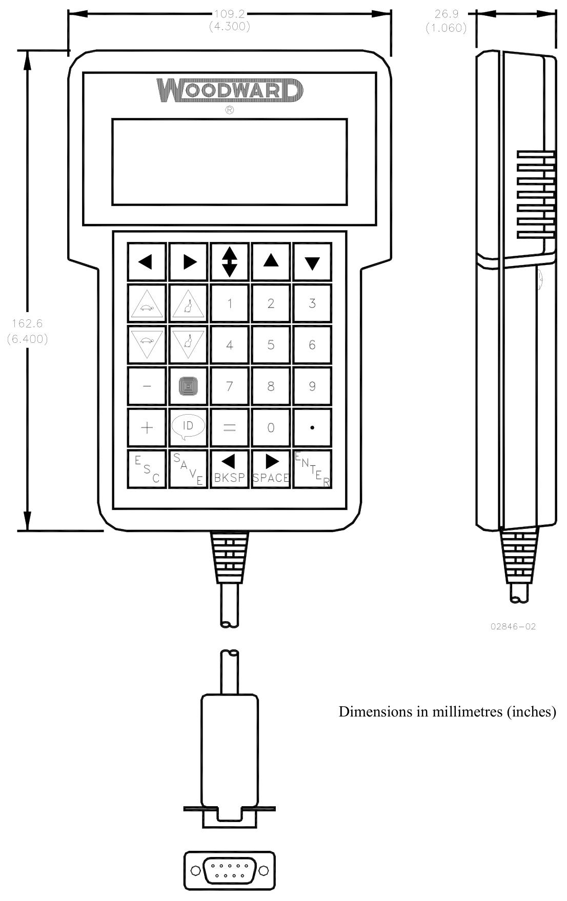
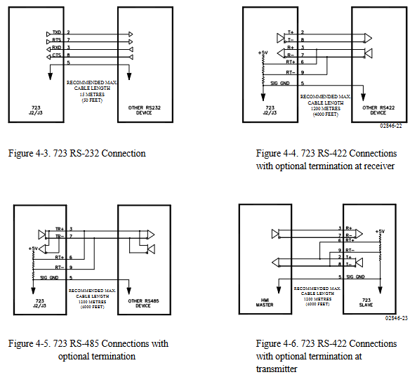
Communication port: The communication port (J1) of the programmer is RS-422, 9-pin D-type connector, 1200 baud rate, full duplex; The communication ports (J2 and J3) are RS-232, RS-422 or RS-485, 9-pin D-type connector, 1200-38400 baud rate, full duplex.
Environmental parameters: working environment temperature -40 to+70 ° C (-40 to+158 ° F), storage temperature -55 to+105 ° C (-67 to+221 ° F), humidity at 38 ° C is 95%, anti electromagnetic interference/radio frequency interference complies with MIL-STD 461C (Parts 5 and 9) in the United States, humidity complies with MIL-STD 810D Method 507.2 Procedure III in the United States, mechanical vibration is a swept sine wave of 24-2000 Hz, constant acceleration of 2.5 Gs, resonance retention -1 million cycles, total time per axis is 3/4-6 hours, mechanical impact complies with MIL-STD 810C Method 526.2 Procedure I (basic design testing), Procedure II (transport drop testing, packaging) in the United States. Program V (Workbench Operation), salt spray complies with ASTM B 117-73.
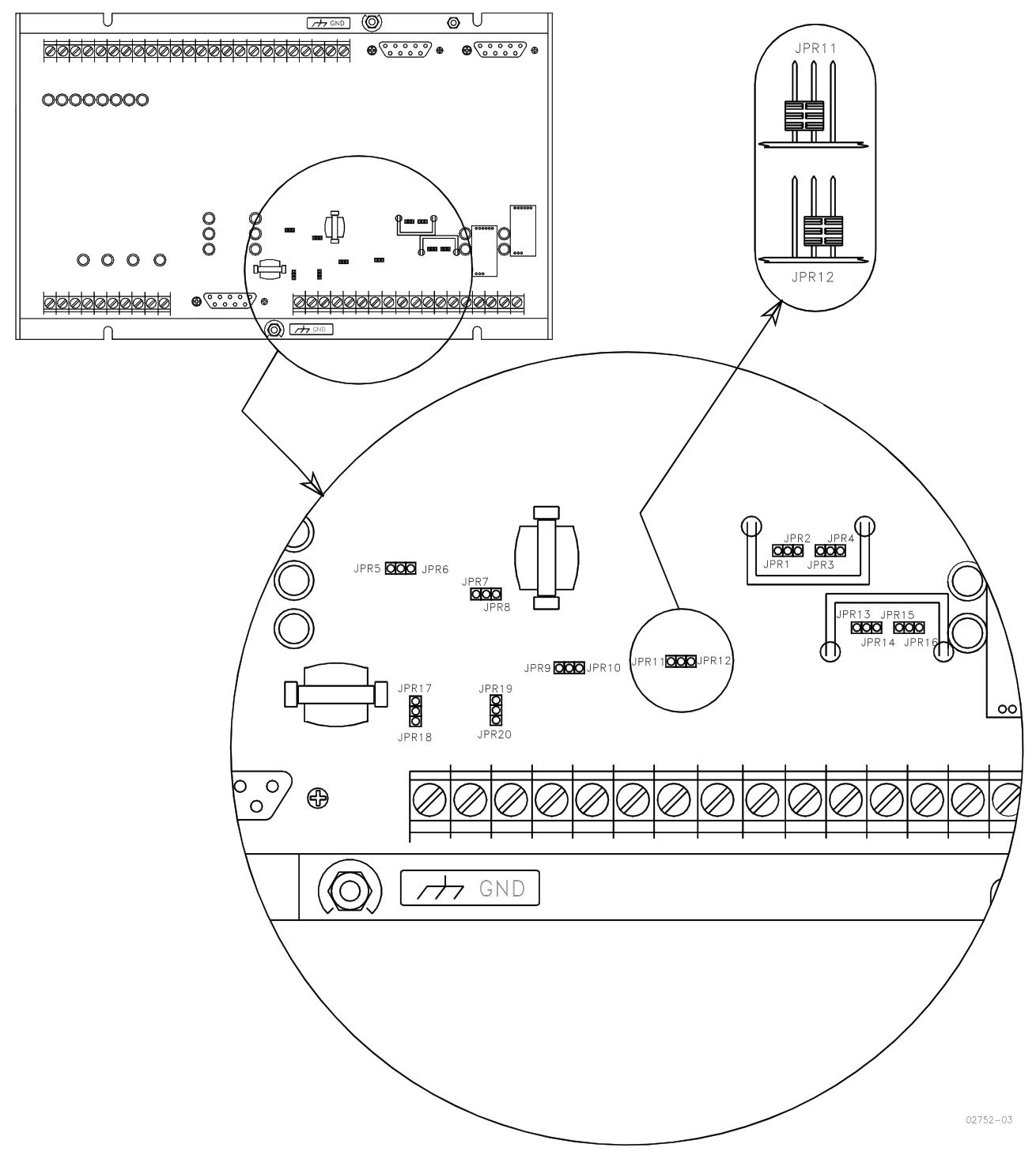
Key points of installation
Unpacking and Inspection: Before installation, it is necessary to read the relevant content on electrostatic discharge protection. When unpacking, handle the electronic controller carefully and check for any damage. If there is any damage, immediately notify the shipper.
Power requirements: The high-voltage version requires a 90-150Vdc voltage source, and the low-voltage version requires an 18-40Vdc voltage source. Both have a maximum power consumption of 40W and should not exceed the input voltage range. If battery power is used, an AC generator or other battery charging equipment should be equipped.
Location selection: The installation location should consider ventilation, maintenance space, moisture resistance, distance from electromagnetic interference sources, and avoidance of vibration. The working temperature range is -40 to+70 ° C (-40 to+158 ° F), and it cannot be installed on the engine.
Electrical connection: All shielded cables must be twisted pair, and do not attempt to tin plated braided shielding layers. All signal lines should be shielded, and the shielding layer should be connected to the nearest chassis ground. The exposed length of wires outside the shielding layer should be as short as possible, not exceeding 50mm (2 inches). The other end of the shielding layer must be open and insulated from any other conductor. Do not lay the shielded signal line together with other wires carrying high currents.
System function
Engine speed related functions
Speed sensing: The controller has two speed sensing inputs, which can be configured as torsional filtering (to make operation smoother, suitable for flexible couplings) or high signal selection (to achieve speed sensing redundancy, enabled when one signal fails). If a torsion filter is used, the speed sensors should be located on both sides of the coupling; If high signal selection is used, the two speed sensing devices should be located on the same speed measuring disc. Speed sensor # 2 can also be configured to detect the speed of the turbocharger.
Speed filtering: Each speed sensor input has a low-pass filter that can filter out unwanted frequencies on the speed sensor. If tuned above 15.9Hz, the filter will be automatically disabled. In addition, a notch filter can be enabled, and its filtering frequency should be set to the resonance frequency of the velocity signal that needs to be filtered. The filtering Q factor can adjust the attenuation degree of the signal frequency filtered by the band stop filter.
Speed control: including idle speed, rated speed settings, overspeed trip function (starting and stopping when the set speed is reached to prevent overspeed), as well as minimum and maximum speed reference limits and acceleration/deceleration rate control.
Synchronization and load control function
Engine start: When the Run/Stop contact is closed (or configured to be open), the speed reference is at idle. When the engine speed exceeds the idle/rated switching speed, the speed reference will ramp up and down at an acceleration/deceleration rate to the rated speed, which can be interrupted by temporarily closing the deceleration contact. If the idle/rated selection function is enabled, after the engine is started, the idle or ramp to rated speed is determined based on the contact position.
Synchronization function: When the engine reaches the rated speed and maintains the synchronization readiness delay time within the synchronization readiness limit, the "ready synchronization" state is achieved through Modbus ® Convey as True. The speed reference can be adjusted by inputting or adding or subtracting contacts through the unit synchronizer to achieve synchronization with the busbar. Alternatively, after the auxiliary contacts of the generator circuit breaker are closed, the bias speed reference can be input through the system synchronizer to achieve cross busbar connection or synchronization with the grid.
Droop control: When the synchronous/droop contacts are open and the auxiliary contacts of the generator circuit breaker are closed, the following droop modes operate. Calculate the speed droop value based on the droop percentage and engine load. The engine load comes from the input of the megawatt sensor. If the signal fails, it is determined based on the output position of the actuator. At the same time, provide a "droop pulse" function to prevent the engine from sinking into reverse power when connected to the bus in droop mode.
Synchronous load distribution: When the synchronous/droop contacts are closed, and the auxiliary contacts of the generator circuit breaker are closed and the load input signal is normal, synchronous load distribution is enabled. The first online machine immediately closes the relay K4 contact on its load sharing circuit. The subsequently selected synchronous units will adjust the load according to the automatic loading/unloading rate until the load shared with the synchronized units is within the specified load sharing error range. At this point, relay K4 closes to connect to the load sharing circuit and achieve load balancing. It also has an automatic soft unloading function. When the unloading contact is closed (instantaneously), the engine load decreases at an automatic unloading rate to the unloading trip level, and then a command to open the generator circuit breaker is issued.
Megawatt control: When the auxiliary contacts, grid contacts (if used), and megawatt control contacts of the generator circuit breaker are closed and the megawatt load input is not disabled, operate in megawatt control mode. The megawatt reference value can be adjusted by adding or removing contacts, or based on internal megawatt reference or remote reference (4-20mA or Modbus) ®) Adjustment. If the remote reference input fails, the megawatt reference will lock the last healthy value.
Protection and restriction functions
High/Low Frequency Protection: In megawatt control mode, it can be configured to open the grid and/or generator circuit breakers or switch to droop mode (megawatt coverage function) when the grid frequency is too high or too low.
Limiting functions: including start-up and maximum fuel limiter (limiting excessive fuel supply or flooding during engine start-up), engine shutdown limiter, frequency load limiter (limiting engine load when grid frequency exceeds preset limits during megawatt control), boost air pressure limiter (providing fuel limitation based on 4-20mA boost air pressure input signal), etc.
Load rejection function: When the generator circuit breaker or grid circuit breaker is opened and the load is above a certain level, the load rejection algorithm takes effect, driving the actuator output to zero for a period of time to reduce speed overshoot.
- YOKOGAWA
- Reliance
- ADVANCED
- SEW
- ProSoft
- WATLOW
- Kongsberg
- FANUC
- VSD
- DCS
- PLC
- man-machine
- Covid-19
- Energy and Gender
- Energy Access
- Renewable Integration
- Energy Subsidies
- Energy and Water
- Net zero emission
- Energy Security
- Critical Minerals
- A-B
- petroleum
- Mine scale
- Sewage treatment
- cement
- architecture
- Industrial information
- New energy
- Automobile market
- electricity
- Construction site
- HIMA
- ABB
- Rockwell
- Schneider Modicon
- Siemens
- xYCOM
- Yaskawa
- Woodward
- BOSCH Rexroth
- MOOG
- General Electric
- American NI
- Rolls-Royce
- CTI
- Honeywell
- EMERSON
- MAN
- GE
- TRICONEX
- Control Wave
- ALSTOM
- AMAT
- STUDER
- KONGSBERG
- MOTOROLA
- DANAHER MOTION
- Bentley
- Galil
- EATON
- MOLEX
- Triconex
- DEIF
- B&W
- ZYGO
- Aerotech
- DANFOSS
- KOLLMORGEN
- Beijer
- Endress+Hauser
- schneider
- Foxboro
- KB
- REXROTH
- YAMAHA
- Johnson
- Westinghouse
- WAGO
- TOSHIBA
- TEKTRONIX
- BENDER
- BMCM
- SMC
- HITACHI
- HIRSCHMANN
- XP POWER
- Baldor
- Meggitt
- SHINKAWA
- Other Brands
- UniOP
- KUKA
- IBA
- Beckhoff
- ADLINK
-
Beckhoff CX5020-0112 - PLC Module
-
Beckhoff CP2912-0000 - Control Panel
-
Beckhoff C6920-1047-0030 - industrial control cabinet control PC
-
BECKHOFF CX1020-0121 - CPU Module Power Supply Setup
-
Beckhoff EL6752 - DeviceNet Master EtherCAT Terminal
-
Beckhoff IP1002-B518 - Fieldbus Box Module
-
Beckhoff CP6606-0001-0020 - 7 inch Economy Panel PC incl. Connection Cable
-
Beckhoff CX5010-0111 - Controller Module
-
BECKHOFF AX2020-S62000-520 - SERVO DRIVE 5.76
-
Beckhoff EL1904 - 4-Channel Digital Input Module
-
BECKHOFF AX5201-0000 - Servo Drive
-
Beckhoff CP7201-1000-0000 - Industrial PC with Touch Screen
-
Beckhoff BK7350 - module Bus Coupler
-
BECKHOFF C6930-0010 - PLC PC Industrial PC
-
Beckhoff AX5125-0000 - Servo Amplifier
-
Beckhoff CX2100-0914 - Power Supply for External UPS for CX20xx
-
Beckhoff CP6608-1000-0010 - Control Panel
-
Beckhoff EL7221-9014 - EtherCAT Terminal, 1 Channel Motion Interface, 48 V DC
-
BECKHOFF CP2919-0000 - Multitouch Built-In Control Panel 24VDC 19"
-
BECKHOFF C6015-0010 - TWINCAT2 Single Core 1.46GHz Industrial PC
-
Beckhoff CU8803-0000 - Controller Module Transmitter
-
BECKHOFF CU1521-0000 - EtherCAT media converter
-
Beckhoff CX5140-0111 - Control Embedded PC HW 3.1 + Flash Card CX2900-0028 4GB
-
Beckhoff AX2513-B200 - Servo Amplifier Servodrive
-
Rexroth MSK061C-0600-NN-M1-UP1-NNNN - Engine Servo Motor
-
Beckhoff AM3031-0C01-0000 - Servo Motor
-
BECKHOFF CP7201-1000-0000 - Industrial PC with touch screen
-
BECKHOFF C6925-0000 - PLC Module Industrial PC
-
BECKHOFF EL5151-0021 - PLC module Encoder Interface
-
Beckhoff CX5130-0125-1001 - Module Embedded PC
-
BECKHOFF EP3356-0022 - EtherCAT Box Module
-
BECKHOFF AX5203-0000 - SERVO DRIVE
-
B&R X20IF1082 - COMMUNICATION INTERFACE MODULE POWER LINK
-
BECKHOFF EL7342 - PLC Module 2-Channel DC Motor Output
-
BECKHOFF CX8190 - Ethernet Controller
-
BECKHOFF CX2020-0120/4GB - CPU CX2100-0904 3x EL6900 EL1904 16GB RAM
-
Beckhoff CX5130-0112 - Module Embedded PC
-
Beckhoff CP7701-0001-0020 - Panel-PC Touch Panel 12" ELO Accutouch AMD ALX 500MHz
-
BECKHOFF CX5020-0111 - Embedded PC Controller
-
Beckhoff CX2040-0100 - Embedded PC HW: 4.0 + CX2100 0014 + 4GB CFast Card
-
Beckhoff CP6512-0001 0030 - Control Panel
-
beckhoff CX9020-0111-0900 - Controller Modules
-
Beckhoff IE3112 - Module Fieldbus Box
-
BECKHOFF CX8051 - PLC Module
-
BECKHOFF CX1100-0920 - module Power Supply
-
Beckhoff CP7921-1075-0000 - Control Panel
-
B&R 3NC352.6 - PLC Module
-
Beckhoff CX8095 - module Controller
-
beckhoff CX1020-0021 - CPU controller module
-
BECKHOFF BK9103 - PROFINET BUS COUPLER
-
Beckhoff C6930-0050 - Schaltschrank-Industrie-Pc Core i7-4700 CPU+FC9062 Modules
-
Beckhoff AM8013-0DH0-1001 - Servo Motor
-
BECKHOFF EPP3184-0002 - Module EtherCAT-P Box
-
BECKHOFF AM8041-0H10-0000 - servo motor
-
BECKHOFF CX1010-0100 - Embedded PC Module System
-
beckhoff CP2916-0000 - Industrial touch screen
-
Beckhoff C6110 - Industrial PC Boser HS6237
-
Beckhoff CX1010-0111 - CPU Module Setup
-
Beckhoff EL3751 - EtherCAT Terminal 1 Channel Analog Input Multifunction 24 Bit
-
BECKHOFF AX5721-0000 - Encoder Interface Card
-
Beckhoff CX1020-0122 - module Embedded PC
-
BECKHOFF CP3921-0000 - Control Panel
-
BECKHOFF CX2040-0155 - STANDARD CPU MODULE INTEL I7 2715QE 2.1GHz
-
BECKHOFF CX5020-0111 - Controller module
-
Beckhoff AX5201-0000-0200 - servo drive
-
BECKHOFF CP2921-0000 - Multi-touch built-in Control Panel with DVI/USB
-
BECKHOFF CP3907-0000 - Touch Panel
-
Beckhoff CX5120-0115 - CPU Module
-
Beckhoff KL3361 - PLC Module Oscilloscope Terminal
-
Beckhoff CX1000-0111 - Embedded PC System Combination
-
Beckhoff AM8023-0E20-0000 - Servo motor with Tramec EP75/2 Transmission
-
beckhoff am8533-2f10-0000 - servo motor
-
BECKHOFF EL5042 - EtherCAT Terminal
-
Beckhoff CX9001-1001 - PLC Module
-
BECKHOFF CX9020-0112 - Digital Module CPU Controller
-
BECKHOFF CP6709-0001-0000 - Touchpanel
-
Beckhoff 1004B2060000 - Communication Module
-
Beckhoff CX5020-0112 - PLC Controller
-
BECKHOFF EL2904 - EtherCAT Safety Input Output Module 24V
-
Beckhoff CX2040-0142 - Embedded PC Controller Module
-
BECKHOFF AM8121-0F20-0000 - SERVO MOTOR
-
Beckhoff CX9020-0112 - CPU Module
-
BECKHOFF CB3050-0008 - PCB Motherboard Board
-
Beckhoff EK1512-0010 - PLC Module EtherCAT Junction
-
BECKHOFF CX1001-0121 - Embedded PC And CPU Basic Module Controller
-
Beckhoff C6032-0070 - Industrial PC
-
Beckhoff CX1020-0122 - Module Embedded PC
-
BECKHOFF CX8010 - Controller Module
-
BECKHOFF EK1818 - Modules EtherCAT Bus Coupler
-
BECKHOFF CX5140-0155 - PLC Embedded PC
-
BECKHOFF CX1100-0910 - Power Supply Module
-
Beckhoff CX1001-0121 - CPU Module + CX1000-C00L + CX1100-0002 + CX1000-N001
-
Beckhoff CP6801-0001-0010 - Control Panel
-
BECKHOFF BK9103-1005 - Bus Coupler PROFINET
-
Beckhoff AX5203-0000-0202 - 161336 Digital Compact Servo Amplifier 2 Channel
-
BECKHOFF CX5020-0111 - Controller module
-
BECKHOFF CP7032-1031-0010 - Cp-Link Control Panel
-
Beckhoff AX5112-0000-0200 - Servo Driver
-
Beckhoff BX8000-0000 - RS232/RS485 Bus Terminal Controller | HW:1.4
-
BECKHOFF CX2020-0120 - CPU MODULE WITH CX2100 Power Supply
-
Beckhoff EL4012 - Module EtherCAT Terminal
-
BECKHOFF CP6204-0001-0030 - ECONOMY INSTALLATION CONTROL PANEL
-
Beckhoff CP6833-0001-0011 - Built-In Control Panel-Without Control Panel Monitor
-
BECKHOFF EK1521-0000 - module EtherCAT junction
-
Beckhoff EP3314-0002 - EtherCAT Compact Box M12 4x Analog Input Thermoelements
-
Beckhoff CX8090 - PLC modules Controller
-
Beckhoff AM8033-0JG0-0000 - Servo Motor
-
Beckhoff CP9035.2 - CP9035 capture card
-
Beckhoff CP7802-1241-0010 - Industrial Touchscreen 15 Inch
-
Beckhoff BX8000-0000 - Module Bus Terminal Controller
-
BECKHOFF IE1002-0000 - Junction box
-
Beckhoff AM237S-0021 - Servomotor
-
Beckhoff EL2564 - EtherCAT Terminal, 4-channel LED output, 5-48VDC, 4A, RGBW
-
BECKHOFF EL1918 - EtherCAT Terminal 8-Channel Digital Input 24V DC
-
Beckhoff CB3052-0005 - Circuitboard Motherboard
-
Beckhoff AM8023-2E11-0000 - Servomotor
-
Beckhoff CX8190 - Ethernet Controller
-
BECKHOFF EL4038 - Module EtherCAT Terminal
-
B&R 5PC910.SX01-00 - APC910 Industrial PC | i5-6440EQ 8GB
-
Beckhoff CP9030-A002 - CP-Link Karte Version: 1.1
-
BECKHOFF BK7200 - CTNET Control Techniques Bus Coupler
-
Beckhoff CP2616-0000 - Multi-Touch Touchscreen Panel for 24V DC Automation
-
BECKHOFF LOT 31 modules - PLC Module Bundle
-
BECKHOFF EJ2889-0000 - Module EtherCAT Plug-in Module
-
BECKHOFF AM8043-0H20-0000 - Servomotor
-
BECKHOFF EL3154 - module EtherCAT Terminal
-
Beckhoff C6017-0030 - Industrial PC
-
BECKHOFF CX9020-0112 - CPU Module

K-JIANG

Add: Jimei North Road, Jimei District, Xiamen, Fujian, China
Tell:+86-15305925923