
K-WANG
+086-15305925923
Service expert in industrial control field!


Product
Article
NameDescriptionContent
Adequate Inventory, Timely Service
pursuit of excellence


Ship control system
Equipment control system
Power monitoring system
Current position:
新闻动态
newS
Brand
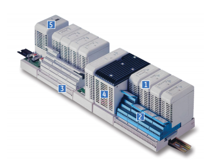
GE 8034-CC-12 Intrinsically Safe Carrier Extension
GE 8034-CC-12 Intrinsically Safe Carrier Extension
GE 8034-CC-12 Intrinsically Safe Carrier Extension
♦ 8 inputs - any combination of inputs and outputs
♦ Certified for use in SIL 2 safety applications
♦ Non-arcing inputs and outputs
♦ Output channels rated up to 2A continuous
♦ Inputs for dry contact switches
♦ 24Vdc Bussed Field Power required from 8914-PS-AC
MODULE SPECIFICATION
See also System Specification
Number of channels ..............................................................8
(independently configured as inputs or outputs)
INPUTS
ON/OFF threshold current ....................................0.9mA (typ.)
O/C Voltage......................24V dc (typ.) - depends on BFP Supply
Wetting current ......................................................1.2mA (typ.)
Minimum pulse width detected........................................5ms
Max input frequency in pulse counting mode (no debounce) 30Hz
Isolation (any channel to Railbus).......................................250V ac
OUTPUTS
Maximum Output Current per Channel ................................2A
Maximum Output Current per Module
Continuous ........................................................................................6A
Non-continuous (<10 seconds)..........................................................8A
INPUT CONFIGURABLE PARAMETERS
Filter time interval ....................................0 to 8s (in 1ms steps)
Earth Leakage Detection Channel ............................ON/OFF
Latch inputs ........................................................enable /disable
Latch polarity ....................................latch on high/latch on low
Pulse counting ....................up transition/down transition/disable
Line fault detection.......... none/open circuit/open & short circuit
OUTPUT CONFIGURABLE PARAMETERS
Output type ..............................................pulse/discrete/pattern
Pulse width................................................................1ms to 60s
Line fault detection*..........open line & short circuit detect /disable
* Normally de-energised channels only
RESISTANCE MEASUREMENT ACCURACY
For normally de-energised output open and short-circuit
detection.
With forward biased test current
.................................... ±(3.4%+5.3Ω) for line resistance ≤ 220Ω
..greater of: ±7% or ±(3.1%+27Ω) for line resistance >220Ω, <1kΩ
With reverse biased test current
................................................greater of: ±7% or ±(3.1%+430Ω)
RESPONSE TIME
Input Signal change to availability on Railbus .....5ms (max.)
Railbus command to output change .......................1ms (max.)
HAZARDOUS AREA SPECIFICATION
Protection Technique.......................................EEx nA nL IIC T4
Location (FM and CSA) ............Class 1, Div.2, Grps A,B,C,D T4
POWER SUPPLIES
System Power Supply ........................50mA (typ.), 70mA (max.)
Bussed Field Power Supply
All channels configured as inputs ................................50mA (max)
Any channels configured as output......50mA + output load currents
MECHANICAL
Module key code ..................................................................B6
Module width ..................................................................42mm
Weight ................................................................................210g
For recommended and compatible Field Terminals, see
Field Terminal - Specification and Selection Guide.
- YOKOGAWA
- Reliance
- ADVANCED
- SEW
- ProSoft
- WATLOW
- Kongsberg
- FANUC
- VSD
- DCS
- PLC
- man-machine
- Covid-19
- Energy and Gender
- Energy Access
- Renewable Integration
- Energy Subsidies
- Energy and Water
- Net zero emission
- Energy Security
- Critical Minerals
- A-B
- petroleum
- Mine scale
- Sewage treatment
- cement
- architecture
- Industrial information
- New energy
- Automobile market
- electricity
- Construction site
- HIMA
- ABB
- Rockwell
- Schneider Modicon
- Siemens
- xYCOM
- Yaskawa
- Woodward
- BOSCH Rexroth
- MOOG
- General Electric
- American NI
- Rolls-Royce
- CTI
- Honeywell
- EMERSON
- MAN
- GE
- TRICONEX
- Control Wave
- ALSTOM
- AMAT
- STUDER
- KONGSBERG
- MOTOROLA
- DANAHER MOTION
- Bentley
- Galil
- EATON
- MOLEX
- Triconex
- DEIF
- B&W
- ZYGO
- Aerotech
- DANFOSS
- KOLLMORGEN
- Beijer
- Endress+Hauser
- schneider
- Foxboro
- KB
- REXROTH
- YAMAHA
- Johnson
- Westinghouse
- WAGO
- TOSHIBA
- TEKTRONIX
- BENDER
- BMCM
- SMC
- HITACHI
- HIRSCHMANN
- XP POWER
- Baldor
- Meggitt
- SHINKAWA
- Other Brands
- UniOP
- KUKA
- IBA
- Beckhoff
- ADLINK
91
-
Beckhoff KL3162 - PLC Module KL 3162
-
Beckhoff EL3255 - PLC module
-
Beckhoff AX5201-0000 - servo driver
-
Beckhoff CX5130-0125 - Embedded PC Intel Atom 1.75GHz processor, 4GB DDR3 RAM
-
Beckhoff CU1521 - industrial switch
-
Beckhoff C6920-1057-0030 - #NAME?
-
B&R 7CP476.60-1 - 1 module 1
-
Beckhoff KL2552 - PLC module
-
Beckhoff CP6223-0002-0060 - #NAME?
-
Unknown BK7350-1060 - EtherCAT bus coupler
-
Beckhoff CX2040-0155 - Automation Basic CPU module, Windows 10 IoT Enterprise
-
Beckhoff CX5230-0175 - 000029724 Embedded PC Industrial PC On Rail
-
Beckhoff EL4134 - PLC Modules
-
Beckhoff EK1100 - automation coupling module EtherCat coupler coupling modules
-
Beckhoff EL6201 - Programmable Controller Module
-
Beckhoff CX2033-0175 - 000107116 embedded PC
-
Beckhoff AM3021-0C40-0000 - #NAME?
-
Beckhoff CX1020-0021 - CPU Module
-
Beckhoff CX2030 - PLC CPU Module
-
Beckhoff CX5130-0120 - PLC Modules
-
Beckhoff CX5230-0175 - 000029724 Embedded Controller Auf Schiene Industrial Pc
-
Beckhoff CX5130-0175 - PC CPU Module HW 4.4 Intel Atom Industrial CX2900 0038 40GB
-
Beckhoff AX5125-0000-0200 - #NAME?
-
Beckhoff KL3011 - One PLC Module
-
Beckhoff CX2020-0120 - 4 GB Basic CPU Module
-
Beckhoff CX1100-0920 - PLC CPU Module Module
-
AB 20F11NC3P5JA0NNNNN - Industrial Automation Part
-
Beckhoff AX5206-0000-0200 - #NAME?
-
Beckhoff CP6700-0001-0050 - , -
-
Beckhoff BECKHOFF-FOR-CX2000-4GB-CFAST-CARD-SLC-FLASH - - - -
-
B&R X67BC6321.L12 - X67 SYSTEM
-
Beckhoff CX9000-0001 - Controller module
-
Beckhoff AX5206-0000-0200 - #NAME?
-
Beckhoff CP2919-0000 - Multitouch Built In Control Panel 24VDC 19"
-
Beckhoff CP6032-0000-0010 - - 15" OPERATOR CONTROL PANEL
-
Beckhoff KL2791 - PLC module
-
Beckhoff CP7902-0001-0000 - - Touch Panel Power Supply 24VDC
-
Beckhoff CP6702-0001 - Open Interface Panels
-
Beckhoff CU8800-0010 - Communication / Interface Module Module
-
Beckhoff C6920-0010 - Driver
-
Beckhoff EL6614 - EtherCAT / Bus Terminal
-
Beckhoff AX5203-0000-0200 - #NAME?
-
Beckhoff EK1322 - 2 port EtherCATP junction Rev 0017
-
Beckhoff EP2349-0021-16 - EtherCAT Box - 16 Channel Module
-
Beckhoff CP6801-0021-0010 - Touch Panel - 12" 14 1 1020
-
Beckhoff CX1020-0112 - - N00 N010 CX1100 0004 PLC CONTROLLER R1S13.7
-
Beckhoff EL2784 - EtherCAT / Bus Terminal Module
-
Beckhoff CX2020-0155 - PLC CPU Module Module
-
Beckhoff EK1914 - PLC EK 1914 Module
-
Beckhoff Cx5130-0122 - PLC CPU Module
-
Beckhoff CX5010-0112 - CPU module
-
Beckhoff CP7811-0001 - - 0 0
-
Beckhoff EL3162 - controller module
-
Beckhoff CU2508-0000 - 8 Port Port Multiplier PLC Processor
-
Beckhoff CX5010-1112 - Mod CPU Module K Bus Windows Runtime TwinCAT 2 NC
-
Beckhoff BECKHOFF-CX2100-0914-CX21000914 - Industrial Automation Part
-
Beckhoff CX1500-M310 - PLC Module
-
B&R 7CP476.60-1 - 1 module 1
-
Beckhoff EL5042 - EtherCAT / Bus Terminal
-
B&R AT6402 - X20 PLC MODULE X20 ORIGINAL
-
Beckhoff CP7802-1327-0010 - #NAME?
-
Beckhoff CX1100-0002 - Power Module
-
Beckhoff CX2040-0155 - PLC CPU Module
-
Beckhoff EP1809-0021 - PLC Modules
-
Beckhoff CX2040 - 0142 Communication Module
-
Beckhoff CX2900-0033 - PLC CPU Module
-
Beckhoff CX2500-0030 - Interface Module
-
Beckhoff EK1100 - Module Ethernet Kommunikaton Modul
-
Beckhoff KL4428 - Bus Terminal 8 Channel Analog Output
-
Beckhoff CX5130-0122 - embedded PC CPU module 4 GB industrial PC CPU module HW 3.5
-
Beckhoff CX9020-0111-1002 - PLC CPU Module
-
Beckhoff CP6929-0001-0000 - Touchscreen Panel 6.5" ELO Model -
-
Beckhoff EP4174-0002 - Module HTP0
-
Beckhoff CP6092-0011-0000 - - Touch Screen 15" Panel
-
B&R 5WCC00000440K0-001 - PANEL PC 2100 SYSTEM UNIT AUTOMATION PANEL
-
Beckhoff CX2100-0014 - Original
-
Beckhoff CX5120-0115 - 3243
-
Beckhoff CP3919-1039-0011 - Multi Touch Control Panel - 19" G190ETN01.2
-
Beckhoff CX9001-0101 - PLC Module QW
-
Beckhoff BECKHOFF-CX5120-121 - Industrial Automation Part
-
Beckhoff BECKHOFF-BX8000-0000 - Industrial Automation Part
-
Beckhoff AX511200000200 - AX5112 0000 0200 Servo Driver
-
Beckhoff EL2564 - EtherCAT Terminal, 4 channel LED output, 5 8VDC, 4A, RGBW
-
Beckhoff KL4494 - EtherCAT / Bus Terminal
-
B&R 5e9000.17 - Control Panel
-
Beckhoff BX8000 - PLC Module
-
Beckhoff AS1060-0110 - , Stepper Motor Precision .........
-
B&R 0702-10B - 6PPT50. Touch Panel
-
Beckhoff C6930-0050 - Schaltschrank Industrie Pc Core i7 4700 CPU+FC9062 Module
-
Beckhoff KL2702 - PLC Controller Module
-
Beckhoff EL4038 - Communication Module
-
Beckhoff EK1110-0008 - EtherCAT / Bus Terminal Module
-
Beckhoff CX5020-0111 - PLC CPU Module
-
Beckhoff CP7232-0001-0050 - #NAME?
-
Beckhoff FC3101-0000 - communication module
-
Beckhoff EL6930 - EtherCAT Klemme
-
Beckhoff EL6631 - EtherCAT / Bus Terminal
-
Beckhoff EK1100 - ,EL2202,EL1904,EL1809,EL9189,EL9188,EL2809,EL3122,EL3102,EL4102
-
Beckhoff EL6695 - EtherCAT / Bus Terminal
-
Beckhoff CX1500-M510 - CX1020 N000 CX1020 0011 CX1100 0002 Controller Set
-
Beckhoff AM8052-1F20-0000 - - motor -
-
Beckhoff C6925-1004 - Industrial PC
-
Beckhoff 7132-0001 - CPPC
-
Beckhoff CP6001-0011-0010 - - Control Panel 12 inch TFT Display, 001...
-
Beckhoff CX2020-0120 - 4GB CPU ,CX2100 0904 3x EL6900, EL1904 16 GB Memory
-
Beckhoff C6920-0030 - Controller
-
B&R 3DM486.6 - DIGITAL MIXED MODULE DM486
-
Beckhoff KL3361 - PLC Module KL 3361
-
Beckhoff C9900-H391 - operating system
-
Unknown CKS-10T - Industrial Automation Part
-
Beckhoff AX5206-0000 - server Driver
-
Beckhoff CP6800-0001-000 - #NAME?
-
Beckhoff CX1100-0920 - Module 24VDC Controller Module
-
Schneider 140CRP31200 - IPC PLC Module In Box
-
Beckhoff C6930-1001 - Industrial PC
-
Beckhoff FC9002 - FC 9002 Ethernet PCI Network Card
-
Beckhoff EL6070-1296 - license key terminal EtherCAT
-
Beckhoff CP7721-1036-0010 - Display Control Panel
-
Beckhoff FC3101 - 2022 Module
-
Beckhoff EK9300-1007 - EtherCAT / Bus Terminal Module
-
Beckhoff AX8640-0000-0000 - #NAME?
-
Beckhoff CP7932-0001-0000 - - touch screen -
-
Beckhoff CX5020-0110 - HW Version 3.4 CPU Module
-
Beckhoff CP2912-0000 - touch screen in box
-
Beckhoff AX5118-0000-0200 - #NAME?
-
B&R 2EX302.5 - Extension unit EX302
-
Beckhoff CX5140-0111 - 1884
-
Beckhoff EQ8003-2042 - Ethercat I o Module

K-JIANG

Add: Jimei North Road, Jimei District, Xiamen, Fujian, China
Tell:+86-15305925923