
K-WANG


Rockwell Automation 836T Series Differential Pressure Controller
Protection ability: It can resist oil/water flow erosion, prevent cotton wool and dust from entering the shell, and is suitable for scenarios that require environmental sealing.
Rockwell Automation 836T Series Differential Pressure Controller
Product Core Description
1. Basic specifications and applicable scenarios
Model classification: Bulletin 836T, including three types: Type 1, 4, and 13, all designed to be oil tight.
Protection ability: It can resist oil/water flow erosion, prevent cotton wool and dust from entering the shell, and is suitable for scenarios that require environmental sealing.
Connection specifications: The pressure interface is 1/4 "-18 N.P.T.F (American dry sealed cone pipe thread), and the electrical interface includes 1/2" -14 N.P.T (optional Pg 13.5 BS20 specification).
Bellows material: provides two options, each suitable for different media——
Copper alloy corrugated pipe: suitable for water, air, and non corrosive liquids/gases;
316 stainless steel corrugated pipe: suitable for liquids/gases with stronger corrosiveness.
2. Core Structure and Function
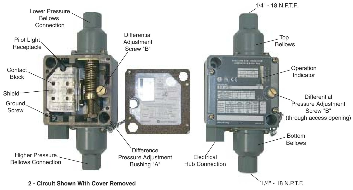
Core components: including Top Bellows, Bottom Bellows (mechanical linkage), Contact Block, Adjustment Differential Screw "B", Pressure Adjustment Difference Bushing "A", Operation Indicator, optional Pilot Light, etc.
Pressure sensing principle: The action is triggered by the pressure difference between two corrugated tubes, regardless of the actual gauge pressure of the system; Adjustable "trip pressure" and "reset pressure", with the difference between the two being the "differential control pressure".
Contact module configuration: provides two specifications to meet different circuit requirements——
Contact module type Contact configuration Circuit function
2-circuit: 1 set of normally open (NO)+1 set of normally closed (NC) supports single pole double throw (SPDT) or independent circuit operation with the same polarity
4-circuit with 2 sets of normally open (NO) and 2 sets of normally closed (NC) supports double pole double throw (DPDT) or two sets of electrically isolated single pole double throw circuits, including isolated terminal 9, which can be connected to external power supply
Working principle
The controller responds to pressure difference changes through a "trigger reset" cycle, with the following specific logic:
1. Trigger (Trip) action (contact switching)
When any of the following conditions are met, the contact module switches states:
The pressure of the bottom corrugated pipe is higher than the preset trigger pressure difference of the top corrugated pipe;
The pressure of the bottom corrugated tube is constant, and the pressure of the top corrugated tube decreases by the preset trigger pressure difference.
2-channel circuit: normally closed circuit (1-2) is open, normally open circuit (3-4) is closed;
4-channel circuit: Two sets of normally closed circuits (1-2, 5-6) are disconnected, and two sets of normally open circuits (3-4, 7-8) are closed.
2. Reset action (contact recovery)
When any of the following conditions are met, the contact returns to its initial state:
The pressure of the bottom corrugated pipe is lower than that of the top corrugated pipe;
The pressure of the bottom corrugated pipe remains constant, while the pressure of the top corrugated pipe increases.
2-channel circuit: normally closed circuit (1-2) is closed, normally open circuit (3-4) is open;
4-channel circuit: Two sets of normally closed circuits (1-2, 5-6) are closed, and two sets of normally open circuits (3-4, 7-8) are disconnected.
3. Key definitions
Trip Pressure: The minimum pressure difference required to trigger contact switching;
Reset Pressure: The maximum pressure difference that triggers contact recovery;
Differential control: The difference between the trigger pressure and the reset pressure can be independently adjusted.
Installation requirements
1. Mechanical installation
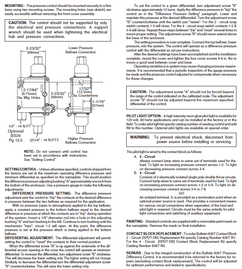
Fixing method: It needs to be fixed on a stable base with two screws, and the installation hole specification is "2-17/64" diameter (6.75mm)+2-23/32 "countersunk hole (69mm)", which can be operated without disassembling the front cover;
Prohibited operation: Do not support the controller solely through electrical or pressure interfaces; When tightening the electrical and pressure interfaces, a support wrench should be used to avoid damaging the components.
2. Precautions for Pre Installation
Before installation, it is necessary to complete the parameter settings ("Setting Control" steps) according to the instructions, otherwise the system cannot be connected;
The pressure interface distinguishes between the "Lower Pressure Bellows Connection" and the "Higher Pressure Bellows Connection", which need to be connected to the corresponding system.
Parameter setting steps
The factory default setting is "maximum trigger pressure difference+minimum control pressure difference" (adjusting the sleeve "A" about 1 inch from the bottom of the housing), which requires the assistance of a pressure gauge for calibration. It is divided into two steps:
1. Trigger the Difference Pressure Setting
The top corrugated pipe is vented to the atmosphere (without pressure), and a constant pressure is applied to the bottom corrugated pipe to trigger the target pressure difference;
Insert a 1/8 "diameter rod into the hole of the adjusting sleeve" A ", rotate the sleeve to the left until the controller" triggers "(circuit 1-2 is disconnected, circuit 1-2 and 5-6 are disconnected);
At this point, the pressure of the bottom corrugated tube is the set trigger pressure difference.
2. Differential Adjustment Control
Adjustment logic: Adjusting screw "B" only changes the reset pressure difference (does not affect the triggering pressure difference) - turn screw "B" clockwise → increase the control pressure difference (reset pressure difference decreases); Turn counterclockwise → reduce the control pressure difference (reset pressure difference increases); When screw "B" is tightened against the bottom of the front cover, control the pressure difference to be minimized.
Specific steps:
Rotate screw "B" clockwise for about 12 turns;
Apply pressure according to the "trigger pressure difference setting" steps to trigger the controller, then reduce the pressure to the target control pressure difference and maintain it;
Rotate screw "B" counterclockwise until the controller is "reset" (2 circuits 1-2 are closed, 4 circuits 1-2, 5-6 are closed);
Repeat the "trigger reset" cycle several times to ensure stable settings;
Screw "B" should not protrude from the bottom of the housing, and adjusting sleeve "A" should not exceed the control range marked on the dial.
3. Complete the setup
After parameter calibration, connect the top corrugated pipe (low pressure end) to the system, install the front cover and tighten 4 screws (torque 6-8 inch pounds) to ensure sealing. It is recommended to regularly check the system pressure and recalibrate as needed.
Optional accessories and maintenance
1. Pilot Light Options
Specification: High brightness neon lamp, suitable for 120V, 60Hz scenes, can be pre installed in the factory or installed on site;
Ordering method: Add "N9" (such as 836T-XXX-N9) after the existing controller model, special specifications require customization;
Wiring rules:
2-channel circuit: Connect the light wire to the load terminal, connect 1-2 for "on when pressure rises" and 3-4 for "on when pressure drops";
4-channel circuit: Connect the light wire to the load terminal (1-2/5-6 or 3-4/7-8), or connect it to an external power source through isolation terminal 9 (ensuring the same polarity of the circuit);
Safety reminder: Disconnect the power supply before installation/maintenance to prevent electric shock.
2. Component replacement and maintenance
Contact module replacement: 2-channel module replacement kit model 836T-N1, 4-channel module kit model 836T-N2;
Overall maintenance: As the controller is an integrated structure, it is recommended to return all faults except for the contact module to the factory for repair (the factory will calibrate to the best performance and test according to specifications);
Nameplate protection: The standard controller nameplate comes with a removable protective film, which needs to be removed during final installation.
Safety and Compliance
CE certification: The product complies with CE standards;
Operation warning: Adjust the components within the marked range to avoid mechanical damage; Corrosive media should use 316 stainless steel corrugated pipes to prevent material failure;
WEEE and Environmental Protection: The document does not mention specific environmental compliance information, please refer to Rockwell Automation's General Environmental Policy.
- YOKOGAWA
- Reliance
- ADVANCED
- SEW
- ProSoft
- WATLOW
- Kongsberg
- FANUC
- VSD
- DCS
- PLC
- man-machine
- Covid-19
- Energy and Gender
- Energy Access
- Renewable Integration
- Energy Subsidies
- Energy and Water
- Net zero emission
- Energy Security
- Critical Minerals
- A-B
- petroleum
- Mine scale
- Sewage treatment
- cement
- architecture
- Industrial information
- New energy
- Automobile market
- electricity
- Construction site
- HIMA
- ABB
- Rockwell
- Schneider Modicon
- Siemens
- xYCOM
- Yaskawa
- Woodward
- BOSCH Rexroth
- MOOG
- General Electric
- American NI
- Rolls-Royce
- CTI
- Honeywell
- EMERSON
- MAN
- GE
- TRICONEX
- Control Wave
- ALSTOM
- AMAT
- STUDER
- KONGSBERG
- MOTOROLA
- DANAHER MOTION
- Bentley
- Galil
- EATON
- MOLEX
- Triconex
- DEIF
- B&W
- ZYGO
- Aerotech
- DANFOSS
- KOLLMORGEN
- Beijer
- Endress+Hauser
- schneider
- Foxboro
- KB
- REXROTH
- YAMAHA
- Johnson
- Westinghouse
- WAGO
- TOSHIBA
- TEKTRONIX
- BENDER
- BMCM
- SMC
- HITACHI
- HIRSCHMANN
- XP POWER
- Baldor
- Meggitt
- SHINKAWA
- Other Brands
- UniOP
- KUKA
- IBA
- Beckhoff
- ADLINK
-
ADLINK HPCI-14S12U - Industrial Control Backplane 12PCI Backplane PCI-14S Passive Backplane
-
ADLINK PCIe-GIE74C - image acquisition card 4-CH GigE Vision PoE+ Frame Grabber
-
ADLINK PCI-8164 - control card 4-Axis Advanced Motion Controller Board
-
ADLINK PCIe-U304 - 4 Port USB3 PCIe Frame Grabbers USB Screw Hole Card
-
ADLINK PCI-9112 - Multi-Function Data Acquisition Card DAQ Card
-
ADLINK PCI-7432 - 51-12013-0A50 4-CH Isolated Numérique I/O PCI Cartes Digital I/O Card
-
ADLINK PCA-6106P3-0C1 REV.C1 - backplane 6-Slot Passive Backplane Board
-
ADLINK PCI-7224 - 24-CH Opto-Isolated Digital I/O PCI Board
-
ADLINK CPCI-7433R(G) - Digital Input Board Rear I/O CompactPCI Card
-
ADLINK EBP-13E4 - 51-46703-0A30 Industrial PC Backplane Passive Backplane
-
ADLINK PCIE-HDV62 - Image acquisition card High Definition Video Frame Grabber
-
ADLINK EBP-13E4 - 51-46703-0A30 Industrial Backplane Board Passive Backplane
-
ADLINK 90111-B1 / CPCI-6770 - PCB CPU MODULE CompactPCI Single Board Computer
-
ADLINK PCI-7248 - DATA ACQUISITION PCI CARD 48-CH Parallel Digital I/O Board
-
ADLINK PCI-7230 - 51-12003-0a50 board PCI7230 32-CH Isolated Digital I/O Card
-
ADLINK PCI2A000CB - 51-20000-0B30 Multi-Function DAQ Card Baseboard
-
ADLINK PCI-8134-005 - 4-Axis Motion Controller Card
-
ADLINK PCI-7224 - 24-CH Opto-Isolated Digital I/O PCI Card
-
ADLINK PCI-7434 - 64-CH Isolated Digital Output Card
-
ADLINK PCI-8132 - motion control card 2-Axis Servo & Stepper Controller
-
ADLINK PCI-8134 - Motion Controller PCI Card 4-Axis Controller Board
-
ADLINK PCI-8164 - Motion Control Card 51-12406-0A40 4-Axis Controller
-
ADLINK 51-12001-0C20 - Circuit Board Data Acquisition Interface Module Hardware
-
ADLINK NuPR0-840 - industrial control motherboard Full-Size PICMG CPU Board
-
ADLINK PCI-7444 - 51-12023-0A10 card 128-CH Isolated Digital Output Board
-
ADLINK PCI-1612B - data acquisition card 4-Port RS-232/422/485 Serial Communication Card
-
ADLINK PCI-6208V 009 - 8/16-CH 16-Bit Analog Output Cards PCB-I-E-482=6BX3
-
ADLINK NUPRO-935A/LV - industrial control motherboard Full-Size PICMG SBC Board
-
ADLINK PCI-9114DG - Multi-Function DAQ Card Data Acquisition PCI Card
-
ADLINK ACL-7130 - Data acquisition card Isolated Digital I/O Board
-
ADLINK ABX-6300D-4E1-BP - board ABX6300D4E1BP Video Interface Expansion Card
-
ADLINK CPCI-6940 - CPCI-6940/D1539/M16-0(EA)-000E 6U CompactPCI Processor Board
-
ADLINK NuPRO-760 - industrial control motherboard Half-Size PICMG SBC CPU Board
-
ADLINK IMB-M42H (G)-0020 - industrial control motherboard LGA1155 Micro-ATX Mainboard
-
ADLINK RTV-24 / PCI-MP4S - 51-12519-1C30 4-Channel Real Time Video Capture Board
-
ADLINK PCI-8134 - 4-Axis Servo & Stepper Motion Controller Card
-
ADLINK MXC-6101D - V.PC000.002.ST.00 Box PC Configurable Embedded Computer
-
ADLINK PCI-8134A - 51-12421-0A10 Motion Control Card 4-Axis Controller Card
-
ADLINK DIN-100S / DIN-100SA1 - Technology SCSI-II TB 100-PIN Terminal Block Board
-
ADLINK DIN-812M001 / DIN812M001 - 51-14034-0A1 51140340A1 Terminal Module Breakout Interface
-
ADLINK PCI-8164 - Servo motion control 4-Axis Advanced Controller Card
-
ADLINK PCIe-GIE64 - Acquisition card GigE Vision PoE+ Frame Grabber
-
ADLINK M-302 - Industrial control motherboard ATX PC Board Mainboard
-
ADLINK PCI-8134 - Motion Controller PCI Card 4-Axis Controller Board
-
ADLINK PCI-RTV24 - Image capture card Analog Video Frame Grabber
-
ADLINK PCI-8102 - Motion control card 2-Axis Servo & Stepper Controller Board
-
ADLINK PCI-9112 REV.B1 - Card Multi-Function Data Acquisition Card
-
ADLINK HSI-DI32-M-N / HSL-TB32-M-DIN - Discrete I/O MODULE Distributed Automation Module System
-
ADLINK PCI-7296 - IO card REV.A3 96-CH Parallel Digital I/O Card
-
ADLINK DIN-814P-A4 / 814Y - terminal board Motion Control Interface Block
-
ADLINK DIN-814P-A4 - 51-14056-0A10 PCB-I-E-2736=ZA01 Screw Terminal Board Breakout
-
ADLINK M-322 - motherboard Industrial Control Computer Mainboard
-
ADLINK NUPRO-406 REV:B1 - industrial control motherboard Full-Size PICMG CPU Board
-
ADLINK AMP-204C - card DSP-Based 4-Axis Advanced Pulse-Train Controller
-
ADLINK HPCI14S REV.B1 - industrial computer baseboard 14-Slot Passive Backplane
-
ADLINK PCI-7250 - 8-CH Relay Output & 8-CH Isolated DI PCI Card
-
ADLINK EBP-13E2 - baseplate Passive Backplane Industrial Computer Chassis Board
-
ADLINK LPCI-3488A - PCI-GPIB card 51-12801-0A30 acquisition card IEEE-488 Interface Board
-
ADLINK PCI-6216V-GL - 51-12201-0C30 16-CH 16-Bit Voltage Analog Output Card
-
ADLINK ACL-8454 - 16-CH Isolated Digital I/O & 4-CH Counter Card
-
ADLINK HPCI-9S7U - backplane Passive Backplane Compatible with NuPRO-A301 852 841 842
-
ADLINK DAQ-2010-007 - Simultaneous-Sampling Multi-Function Data Acquisition Card
-
ADLINK MP-C154 - 51-64205-0A10 Motion Control Card 4-Axis Controller Board
-
ADLINK MXE-202/mSSD16B/WiFi-BT - Matrix Rugged I/O Platform Embedded Fanless Computer
-
ADLINK CM-920-R-17 - PC/104-Plus Single Board Computer Module Intel Celeron M
-
ADLINK PCI-7250 NSMP - 8-CH Relay Output & 8-CH Isolated DI Card
-
ADLINK PCI-8164 - 4-Axis Motion Controller PCI Card W/ Cable and Breakout Box
-
ADLINK EMX-100 - Ethernet-based 4-axis Motion Controllers Distributed Motion Module
-
ADLINK PCI-8134A - Press control card 4-Axis Motion Controller Board
-
ADLINK M-845EG REV:3.2 - industrial motherboard Pentium 4 Socket 478 Micro-ATX
-
ADLINK PCI-9114A Rev A2 DG - card High-Resolution Multi-Function Data Acquisition Board
-
ADLINK IEC-915GV - REV 1.1 Industrial motherboard Socket 478 CPU Board
-
ADLINK PCI-9111DG(G) - Data Acquisition Card Multi-Function DAQ Card
-
ADLINK HPCI-15S10 REV:B2 - Industrial computer base plate Passive Backplane Board
-
ADLINK NuPR0-840 / NuPR0-840DV - industrial control motherboard Full-size PICMG CPU Board
-
ADLINK RTV-24 / PCI-MP4S - 51-12519-1C30 4-Channel Real Time Video Capture Board
-
ADLINK NUPRO-780 - industrial control motherboard Pentium III Single Board Computer
-
ADLINK PCI-7296 - 0050 card 96-CH Opto-Isolated Parallel DIO Card Set
-
ADLINK NUPRO-780 - industrial control motherboard PICMG Full-Size SBC
-
ADLINK PCI-7248 - 51-12006-0A3 002 Pci 7248 48-CH Parallel Digital I/O Card
-
ADLINK cPCI-6626 - 6U CompactPCI 2.0 Blades i7-2710QE PCB-I-E-2570=9N41
-
ADLINK MXC-6322D(G) - Industrial Fanless Computer
-
ADLINK cPCI-8168-004 - CompactPci NulPC Motion Control Board 51-36402-0A3
-
ADLINK CPCI-7300[G] - COMPACTPCI Digital I/O Card Data Acquisition
-
ADLINK CPCI-6626/2710/M4G - COMPACTPCI COMPUTER BOARD
-
ADLINK cPCI-8168-009 - cPCI NulPC Motion Control Board
-
ADLINK cPCI-6626/2710/M4G - VME CPU Board Computer Board
-
ADLINK CPCI-R6200(G)-0040 - COMPACTPCI CONTROL BOARD
-
ADLINK CPCI-3840/PM18/M1G(G)-3650 - COMPACTPCI CPU Module Single Board Computer
-
ADLINK cPCI-7248 - 48-CH Opto-22 Compatible Digital I/O Module
-
ADLINK DLAP-211-JNX - NVIDIA Jetson Xavier NX Edge AI Inference Platform
-
ADLINK cPCI-3544 - Series 4-Port RS-422/485 Isolated Serial Communications Card
-
ADLINK CM1-86DX3 - PC/104 SBC Stanley Vortex86DX3 CPU 2GB Ram
-
ADLINK DLAP-211-JNX - NVIDIA Jetson Xavier NX Edge AI Inference Platform
-
ADLINK cPCI-3544 - Series 4-Port RS-422/485 Isolated Serial Communications Card
-
ADLINK CM1-86DX3 - PC/104 SBC Stanley Vortex86DX3 CPU 2GB Ram
-
ADLINK PCI-7433 - switch value acquisition card Isolated Digital Input Card
-
ADLINK PCI-9112 - 51-12252-0D20 Multi-Function Data Acquisition Card
-
ADLINK NUPRO-A301 REV:1.4 - industrial control motherboard PICMG Full-Size SBC
-
ADLINK 51-18502-0A10 - Frame Grabber Image Acquisition Interface Card
-
ADLINK PCI-7296 - 51-12009-0A50 PCB-I-E-925=6DX1 96-CH Parallel Digital I/O Board
-
ADLINK PCI-8132 GP A2 - Motion Control Card 2-Axis Servo & Stepper Controller
-
ADLINK PCI-7442 - switch quantity card data acquisition card 64-CH Isolated Card
-
ADLINK HPX-13S4 - baseboard PICMG 1.3 Passive Backplane Chassis Baseplate
-
ADLINK NuPRO-590 / NTC-567-ZM-F36 - Single Board Computer PCB-I-E-1853=9L21 Half-Size SBC
-
ADLINK PCIe-8332 - 16-axis plate Motion Control Hardware Card
-
ADLINK NuPRO-775 REV.B1 - motherboard Pentium 4 Full-Size PICMG SBC
-
ADLINK PXI-3920 - Embedded Controller 3U PXI cPCI System Intelligence Board
-
ADLINK PCI-8134 - driver card motion control card 4-Axis Controller Board
-
ADLINK HSL-DI32-M-N-011 / HSL-TB32-M-DIN - Digital Input & Base Module PLC Distributed I/O System
-
ADLINK PCI-6216V-206 / PCI-208V 009 - 16 CH 16bit analog output card
-
ADLINK NuPro-E330 - 51-41805-0A20 PCB Single Board Computer Host Board
-
ADLINK PCI-1622C - Card 8-Port RS-232/422/485 PCI Serial Communication Board
-
ADLINK PCIe-7432 - 51-18402-0A10 Carte PCIe Avec Plage D'Entrée Élevée Isolated DIO Card
-
ADLINK PCI-7250 - PCI Acquisition Card 8-CH Relay Output Isolated DI Card
-
ADLINK PCI-7230 - 32-CH Isolated Digital I/O Card
-
ADLINK PCI-8164 - PCB 4-Axis Motion Controller Card
-
ADLINK PCI-7854 - Collection card High-Speed Link Distributed Motion Controller
-
ADLINK NuPRO-935A/LV - industrial control computer motherboard Full-Size PICMG SBC
-
ADLINK IMB-M40H - motherboard IH61-AA4 1155 LGA1155 Micro-ATX Mainboard
-
ADLINK PCI-7248 - Linhua 51-12006-0A40 48-CH Parallel Digital I/O Card
-
ADLINK HPCI-14S12U - Linhua industrial computer baseboard Passive Backplane
-
ADLINK PCI-8132 Rev.A2 - 2-Axis Servo & Stepper Motion Controller Card
-
ADLINK ACL-8111 - ISA card Multi-Function DAQ Card
-
ADLINK ACL-8111 - ISA card Multi-Function Data Acquisition Board
-
ADLINK PCI-7200 REV.A3 - Digital I/O card 12MB/s High-Speed Parallel Digital I/O
-
ADLINK PCI-7296 REV.A3 - 96-CH High-Density Opto-Isolated DIO Card
-
ADLINK PCI-7434 - 64-CH Isolated Digital Output Card

K-JIANG

Add: Jimei North Road, Jimei District, Xiamen, Fujian, China
Tell:+86-15305925923