
K-WANG


ABB ACS800 inverter IGBT module
ACS800-02/U2: There is relatively little mention in the document, and the external specifications are R7 and R8. Other information can refer to the relevant content of ACS800-01/U1. Some chapters of the two are common, such as safety instructions, electrical installation design, and braking resistors.
ABB ACS800 inverter IGBT module
Safety Notice
Applicable products: Suitable for ACS800-01/U1 and ACS800-02/U2 products.
Warning and Caution
Warning: Remind of situations that may cause serious injury or death and/or damage to equipment, such as dangerous voltage, electrostatic discharge, etc.
Attention: Remind users of special situations or events, or introduce relevant information on the topic, such as dangerous high voltage at motor cable terminals.
Installation and maintenance work
Only qualified electrical engineers are allowed to install and maintain transmission units.
It is prohibited to install or repair transmission units, motor cables or motors with electricity. After cutting off the input power, wait for at least 5 minutes until the intermediate circuit capacitor is discharged, and use a multimeter to measure and confirm the discharge before operation.
Do not operate control cables when the transmission unit or external control circuit is energized.
All insulation tests must be conducted with the cable disconnected, and ensure the correct phase sequence when reconnecting the cable.
grounding
Proper grounding is necessary to ensure the safety of personnel, reduce electromagnetic radiation and interference. The cross-sectional area of the grounding wire must meet safety regulations, and multiple equipment grounding terminals cannot be connected in series.
In scenarios that comply with European CE standards, cable entrances should maintain a 360 degree high-frequency grounding, and the cable shielding layer should be connected to the protective grounding wire (PE).
Do not install frequency converters with EMC filters in floating or high ground resistance power systems.
Mechanical Installation
The transmission unit is heavy and should not be carried by a single person. When carrying, do not let the front panel bear the weight and rely on lifting the back for transportation.
Ensure that drilling debris does not enter the transmission unit during installation, ensure sufficient cooling space, and do not fix the transmission unit by riveting or welding.
operate
Before debugging the transmission unit, ensure that the motor and driven equipment are suitable for operation within the speed range provided by the transmission unit.
Do not activate the automatic fault reset function of standard applications in situations where danger may occur.
Do not use the main power circuit breaker to control the start and stop of the motor. Instead, use control commands from the control panel keys or transmission unit I/O board.
Permanent magnet motor
When ACS800 is used to drive permanent magnet motors, only scalar control mode can be used.
When the permanent magnet motor is running, do not operate the transmission unit, as its operation transfers electrical energy back to the intermediate circuit. Even if the inverter is not working, the power supply will still charge the transmission system.
During installation and maintenance, use a fuse switch to disconnect the motor from the transmission unit. If possible, lock the motor shaft, connect the motor connection terminals together, and ground them.
Do not operate the permanent magnet motor at speeds higher than the rated speed to avoid overvoltage and capacitor bank rupture.
Product Overview
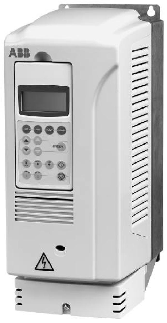
ACS800-01/U1: A wall mounted transmission unit used to control low-voltage AC asynchronous motors, with different external specifications (R2~R6), protection levels including IP21 (NEMA1) and IP55 (NEMA4, indoor only), etc. The control panel is CDP312R, including printed circuit boards such as main circuit board (RINT), motor control and I/O control board (RMIO), etc. The motor control mode can choose direct torque control (DTC) or scalar control.
ACS800-02/U2: There is relatively little mention in the document, and the external specifications are R7 and R8. Other information can refer to the relevant content of ACS800-01/U1. Some chapters of the two are common, such as safety instructions, electrical installation design, and braking resistors.
Installation
Mechanical Installation
Unpacking and inspection: After unpacking, check for any damage to the appearance, verify if the nameplate of the frequency converter matches the order, and check if the optional modules and equipment are complete.
Preparation before installation: Install vertically, place the radiator against the wall, check if the walls and floors of the installation site meet the requirements, ensure that there is enough space around the transmission unit for cooling air circulation, facilitate maintenance and repair, and pay attention to the space requirements when placing equipment of different protection levels up and down.
Installation method: including wall mounted installation and cabinet installation. Wall mounted installation requires marking the installation hole position with a punching template, fixing screws or bolts, installing the transmission unit and tightening it; Attention should be paid to the horizontal installation distance between the frequency converters when installing inside the cabinet, to prevent the recirculation of cooling air, and to set up air baffles.
Electrical installation design
Motor compatibility check: Ensure that the rated voltage and current of the motor meet the requirements, and avoid the rated voltage of the motor being less than 1/2 of the rated input voltage of the transmission unit or the rated current being less than 1/6 of the rated output current of the transmission unit.
Protecting motor windings and bearings: The output pulse voltage of the transmission unit may affect the motor insulation and bearings. ABB du/dt filters, common mode filters, etc. can be used to reduce the impact. Suitable filters and insulated bearings should be selected according to the motor type and power.
Power supply system connection: A manually operated circuit breaker can be installed between the AC power supply and the transmission unit, which must comply with relevant standards, such as using category AC-23B, etc; The input cable needs to be equipped with a fuse group, and the fuse model should be selected according to local safety regulations, input voltage, and rated current of the transmission unit.
Cable selection and wiring: The main power and motor cables need to be selected according to local regulations to meet the requirements of load current and temperature. The protection ground cables need to consider inductance and impedance limitations; It is best to use shielded cables for control cables, with separate routing for analog and digital signals to avoid long-distance parallel routing. When crossing, the angle should be 90 degrees.
electrical installation
Insulation performance inspection: Check the insulation performance of the motor and motor cables, disconnect the transmission unit from the main power supply, use a 1kV insulation meter to measure the insulation resistance of each relative protective ground, and the resistance value should be greater than 1 megohm.
Power cable wiring: Determine the length of wire stripping according to the external specifications, ground the cable shielding layer, connect the main power cable and motor cable to the corresponding terminals, and fix the junction box cover and front cover.
Control cable wiring: Thread the control cable through the entrance hole and connect it to the relevant detachable terminals on the RMIO board, ensuring a secure connection, grounding the shielding layer, and fixing the control cable and front cover.
Maintenance
Maintenance Cycle
Capacitor update: once a year when stored.
Temperature inspection and cleaning of radiator: Depending on the dust content in the environment, it should be done every 6-12 months.
Cooling fan replacement: Replace every five years, and replace spare fans for IP55 units and some IP21 units every three years.
Maintain content
Cleaning of radiator: Remove the cooling fan, use clean and dry compressed air to blow the radiator from bottom to top, while using a vacuum cleaner to absorb dust at the air outlet, and then install the cooling fan.
Cooling fan inspection: Pay attention to the noise of the fan bearings and the temperature of the radiator. Replace them in a timely manner when signs of damage appear, and use ABB designated spare parts.
Capacitor inspection: Electrolytic capacitors are used in the intermediate circuit, with a service life of about 100000 hours. Damage is often accompanied by the main power fuse melting or fault tripping. If there is suspicion of damage, contact the ABB representative office and use designated spare parts.
LED indication: The LED lights on the RMIO board and control panel installation components can indicate faults and normal power status.
Technical data
IEC level: lists the rated capacity, external specifications, air flow rate, heat loss, and other data of different models of ACS800-01 under 50Hz and 60Hz grid power supply.
Capacity reduction
Temperature induced capacity reduction: When the ambient temperature is between+40 ° C and 50 ° C, for every 1 ° C increase, the rated output current decreases by 1%. The rated current Icont.max is not allowed to be applied in environments exceeding 40 ° C.
Capacity reduction caused by altitude: When the altitude is between 1000-4000m, the rated current decreases by 1% for every 100m increase. If it exceeds 2000m, consult the local ABB dealer or office.
Main power cable fuse: provides cable specifications, fuse models, parameters, etc. corresponding to different models of ACS800-01.
Cable entry hole: information such as terminal size, cable diameter, and tightening torque for different external specifications.
Size, weight, and noise: The size, weight, and noise data of each external specification under different protection levels.
Motor wiring: parameters such as voltage, frequency, current, power limit, and recommended maximum motor cable length.
Efficiency and cooling: The efficiency is approximately 98% of the rated power, and the cooling method is an internal fan with a flow direction from the bottom to the top.
Protection level and environmental conditions: Protection levels include IP21 and IP55, as well as operating conditions such as environmental temperature, relative humidity, and pollution level.
Materials and applicable standards: Information on materials such as transmission unit casing and packaging boxes, following international standards such as EN50178, EN60204-1, etc.
Braking resistor
Configuration and selection: Transmission units with external specifications of R2 and R3 include built-in brake choppers, R4 and larger brake choppers are optional (model+D150), and resistors are additional components; When selecting the transmission unit/chopper/resistor, it is necessary to calculate the braking power to ensure that the resistor resistance and heat loss capacity meet the requirements.
Installation and wiring: All resistors must be installed outside the transmission unit module, with flame-retardant materials nearby. They should be connected using cables of the same model as the input cables of the transmission unit, with a maximum allowable length of 10m. The shielding layer should be properly grounded.
Protection and debugging: It is recommended to configure the main circuit contactor for external specifications R2~R5, and whether R6, R7, and R8 are needed depends on the selection situation; A thermal switch should be installed inside the braking resistor and connected to the digital input port as an external fault interlock signal; Activate the brake chopper function during debugging, turn off the overvoltage control function, and check the resistance value setting.
Model Supplement
IGBT MODULE KIT FS450R12KE3/AGDR-61C S 64635875
IGBT MODULE KIT FS300R17KE3/AGDR-66C S 64717839
IGBT MODULE KIT FS300R12KE3/AGDR-62C S 64717812
IGBT MODULE KIT FS450R17KE3/AGDR-61C S 64783831
IGBT MODULE KIT FS225R12KE3/AGDR-71C S 68569303
IGBT MODULE KIT FS300R12KE3/AGDR-72C S 68569541
IGBT MODULE KIT FS450R12KE3/AGDR-71C S 68569354
IGBT MODULE KIT FS225R17KE3/AGDR-76C S 68569583
IGBT MODULE KIT FS300R17KE3/AGDR-76C S 68569362
IGBT MODULE KIT FS450R17KE3/AGDR-71C S 68569591
IGBT MODULE KIT FS450R17KE3/AGDR-72C S 68569427
IGBT MODULE KIT FS300R12KE3/AGDR-71C S 68569346
IGBT MODULE KIT FS450R17OE4/AGDR-71C S TIM FOIL SP 3AXD50000948185
- YOKOGAWA
- Reliance
- ADVANCED
- SEW
- ProSoft
- WATLOW
- Kongsberg
- FANUC
- VSD
- DCS
- PLC
- man-machine
- Covid-19
- Energy and Gender
- Energy Access
- Renewable Integration
- Energy Subsidies
- Energy and Water
- Net zero emission
- Energy Security
- Critical Minerals
- A-B
- petroleum
- Mine scale
- Sewage treatment
- cement
- architecture
- Industrial information
- New energy
- Automobile market
- electricity
- Construction site
- HIMA
- ABB
- Rockwell
- Schneider Modicon
- Siemens
- xYCOM
- Yaskawa
- Woodward
- BOSCH Rexroth
- MOOG
- General Electric
- American NI
- Rolls-Royce
- CTI
- Honeywell
- EMERSON
- MAN
- GE
- TRICONEX
- Control Wave
- ALSTOM
- AMAT
- STUDER
- KONGSBERG
- MOTOROLA
- DANAHER MOTION
- Bentley
- Galil
- EATON
- MOLEX
- Triconex
- DEIF
- B&W
- ZYGO
- Aerotech
- DANFOSS
- KOLLMORGEN
- Beijer
- Endress+Hauser
- schneider
- Foxboro
- KB
- REXROTH
- YAMAHA
- Johnson
- Westinghouse
- WAGO
- TOSHIBA
- TEKTRONIX
- BENDER
- BMCM
- SMC
- HITACHI
- HIRSCHMANN
- XP POWER
- Baldor
- Meggitt
- SHINKAWA
- Other Brands
- UniOP
- KUKA
- IBA
- Beckhoff
- ADLINK
-
Beckhoff EP9224-0037 - 4-Channel Power Distribution Box EtherCAT
-
Beckhoff CX2900-0026 - Solid State Flash Memory Card 20GB CFast
-
Beckhoff BK7500 - SERCOS Interface Fieldbus Bus Coupler Terminal
-
Beckhoff Ep2328-0002 - 4-Channel Input 4-Channel Output EtherCAT Box IP67
-
Beckhoff CX1020-0111 - Controller Kit Combo Interface Modules
-
B&R X20AI2237 - X20 System Analog Input Interface Module
-
Beckhoff CP2221-0010 - Multi-Touch Built-In Panel PC Touchscreen
-
Beckhoff CX1500-M310 - Fieldbus Master Interface Module 24V
-
Beckhoff CX2100-0904 - Power Charging Module Smart UPS Extension
-
Beckhoff CP3918-0000 - Multi-Touch Control Panel 18.5-Inch Monitor
-
Beckhoff CP2915-0000 - 15-Inch Multi-Touch Built-In Control Panel
-
Beckhoff CP7037-1027 - HMI Industrial Control Panel Built-In PC
-
Beckhoff EL3152 - 2-Channel Analog Input Terminal 4-20mA EtherCAT
-
Beckhoff CP6607-0000-0020 - 5.7-Inch Built-In Panel PC HMI Touch
-
Beckhoff EJ1809-0000 - 16-Channel Digital Input Pluggable Signal Level Terminal
-
Beckhoff AM8563-0N10-0000 - Synchronous Servo Motor
-
Beckhoff AX2006-S60600-520 - Compact Servo Drive Inverter
-
Beckhoff AM8053-0K20-0000 - Servo Motor with Planetary Gearbox AG3210
-
Beckhoff AM8042-0FH1-0000 - Synchronous Servo Motor
-
Rexroth R911338600 - IndraControl V HMI Terminal Beckhoff PCI Card FC9002
-
Beckhoff AX5125-0000 - 3 Phase Industrial Servo Drive 1000Hz
-
Beckhoff EP2328-0002 - 4-Channel Digital Input 4-Channel Output EtherCAT Box
-
B&R 7CP476-02 - System 2005 RTD CPU Module 3IF681.86 Interface
-
Beckhoff AX8620-0000-0000 - Power Supply Module Axis Drive System
-
Beckhoff CX1010-0111 - PLC Module CPU Controller 24V
-
Beckhoff AM8043-0H10-0000 - Synchronous Servo Motor
-
Beckhoff C6240-1009 - Control Cabinet Industrial PC Mainframe
-
Beckhoff BX8000-0000 - Bus Terminal Controller HW 4.4 Standalone
-
Beckhoff CP7721-1089-0020 - 12.1-Inch Touch Screen HMI Panel PC
-
Beckhoff CP7132-0001 - Industrial Built-In Panel PC Screen
-
Beckhoff CP2912-0010 - Multi-Touch Built-In Control Panel Display
-
Beckhoff CP2915-0000 - 15-Inch Multi-Touch Built-In Control Panel
-
Beckhoff AM8532-1EN0-0000 - Synchronous Servo Motor
-
Beckhoff AX5203-0000 - 2-Channel Digital Compact Servo Drive
-
Beckhoff CX2020-0141 - Embedded PC Core CPU Module
-
Beckhoff CP6832-0002-0010 - Built-In Industrial Control Panel Display
-
Beckhoff CX5020-0112 - Embedded PC CPU Control Module
-
Beckhoff CX5140-0175 - 4GB Embedded PC CPU Unit 24V
-
Beckhoff EL3681-0030 - Digital Multimeter Calibration Terminal EtherCAT
-
Beckhoff CP7201-1000-0000 - Industrial PC Touch Screen HMI Monitor
-
Beckhoff CP7232-1001-0000 - Industrial Panel PC Touch Screen
-
Beckhoff C6930-1032-0040 - Control Cabinet Industrial PC System
-
Beckhoff AX5125-0000 - 3 Phase Industrial Servo Drive 1000Hz
-
Beckhoff CP3916-1424-0000 - Multi-Touch Built-In Control Panel
-
B&R 1900071142 - Lemoine Fieldbus Communication Interface Module
-
Beckhoff EL2872 - 16-Channel Ribbon Cable Digital Output Terminal
-
Beckhoff CX2030-0120 - Embedded PC CPU Base Module Controller
-
Beckhoff CP3919-0000 - 19-Inch Multi-Touch Control Panel Touchscreen
-
Beckhoff AX5101-0000-0202 - Servo Driver Compact Intelligent Drive 180V
-
Beckhoff CX5130-0135 - Embedded PC Controller Module
-
Beckhoff CP3719-1061-0010 - Multi-Touch Panel PC Outer Housing Enclosure
-
Beckhoff CP3919-1033-0000 - 19-Inch Touch Industrial Panel Keyboard
-
Beckhoff CX5020-0111 - Embedded PC PLC CPU Module
-
Beckhoff FC5102-0000 - 2-Channel CANopen PCI Control Board Card
-
Beckhoff CX9001-1101 - Embedded PC CPU Network I/O System Module
-
Beckhoff CX1100-0920 - Smart Position Sensor Interface Module
-
B&R 4P3040.01-490 - Operator Panel PLC Interface Communication Module
-
Beckhoff CP2612-0000 - Dual-Touch Built-In Panel PC HMI
-
Beckhoff CP7002-1043-0010 - Touchscreen Display HMI Panel Terminal
-
Beckhoff CX9020-0115 - Embedded PC Controller Module
-
Beckhoff CX5140-0155 - 4GB Embedded PC CPU Module Die Industry
-
B&R 7DI435.7 - System 2005 Universal Digital Input Output Module
-
Bihl+Wiedemann BWU1568 - AS-i Master to Profibus Gateway Module
-
Beckhoff C6920-0070 - Control Cabinet Industrial PC 8GB Win 10
-
B&R X20AI2322 - 2-Channel Temperature Analog Input Module
-
Beckhoff CP2912-0000 - 12-Inch Touchscreen Display Monitor Screen
-
Beckhoff CP6022-1001-0010 - 15-Inch Built-In Control Panel
-
Beckhoff AM8031-0D10-0000 - Synchronous Servo Motor
-
Beckhoff CX5010-0111 - Embedded PC Controller CPU Module
-
Beckhoff CP7232-1000-0000 - Industrial Panel PC Touch Display Screen
-
Beckhoff CP7802-0011-0000 - 15-Inch Industrial Touchscreen Control Panel
-
Beckhoff C6320 - Control Cabinet Industrial PC
-
Beckhoff CX1030-0012 - Basic CPU Module Windows CE 6.0
-
Beckhoff CP2919-0000 - Installation Multi-Touch Control Panel
-
Beckhoff CX1020-0000 - Controller Set Stack System Pack
-
B&R 3DO480.6 - System 2005 Digital Output Module
-
Beckhoff EL3101 - 1-Channel Analog Input Terminal Differential +/-10V
-
Beckhoff AX8108-0200-0000 - Axis Feed Module Servo Drive
-
Beckhoff CP7802-1241-0010 - 15-Inch Industrial Touchscreen Control Panel
-
Beckhoff FC2002-0000 - 2-Channel Lightbus Data Acquisition PCI Card
-
Beckhoff CX5120-0155 - 2GB Embedded PC Intel Atom Controller
-
Beckhoff Cx9020-0111 - 1GB Basic CPU Module Embedded PC
-
Beckhoff CP6901-0001-0000 - 12-Inch Economy Built-In Control Panel
-
Beckhoff CX9020-0111 - Embedded PC CPU Basic Module
-
Beckhoff CX5130-0100 - 4GB Embedded PC CPU Module
-
Beckhoff CP2715-0010 - Multi-Touch Built-In Panel PC
-
Beckhoff CX2033-0175 - Embedded PC CPU Module Core i7
-
Beckhoff CP7201-1000-0000 - 12-Inch Touchscreen Panel PC AMAT Green Box
-
Beckhoff EL4038 - 8-Channel Analog Output Terminal 0-10V EtherCAT
-
Beckhoff CP6802-0000-0000 - Built-In Control Panel HMI Screen
-
Beckhoff CP6500-1012-0060 - Control Cabinet PC Interface Unit
-
Beckhoff FC5202-0000 - 2-Channel DeviceNet Master PCI Interface Card
-
Beckhoff CP6606-0001-0020 - 7-Inch Economy Panel PC Touch
-
Beckhoff CP2921-0010 - Multi-Touch Integrated Control Panel Display
-
Beckhoff CP7802-0001-0010 - 15-Inch Touch Screen Control Panel HMI
-
Beckhoff C6920-0050 - Control Cabinet Industrial PC
-
Beckhoff BK9105 - EtherNet/IP Bus Coupler Network Interface
-
Beckhoff 31 Modules - Bus Terminal Slice I/O Lot Assortment
-
Beckhoff CX2020-0120 - Embedded PC Basic CPU Module 8GB CFast Card
-
Beckhoff CP7001-0000 - HMI Control Panel Touch Screen
-
B&R 7EX484.50-1 - System 2005 Controller Base Module Slots
-
Beckhoff EK1322 - 2-Port EtherCAT P Extension Feed-In Terminal
-
Beckhoff CP6606-0001-0020 - 7-Inch Single-Touch Economy Panel PC
-
Beckhoff CP6607-0001-0000 - Economy Installation Operator Panel PC 5.7-Inch
-
Beckhoff AX5103-0000-0200 - Digital Compact Servo Driver 3 Phase
-
Beckhoff CP7802-0001-0010 - 15-Inch Touch Screen Control Panel
-
Beckhoff AX8620 - Power Supply Module Axis System
-
Beckhoff CX2030-0121 - Embedded PC Controller Module
-
Beckhoff CP6606-0001-0020 - 7-Inch Economy Panel PC Touch Screen
-
Beckhoff CX2030-0121 - Embedded PC CPU Module Windows Standard 7
-
Beckhoff BX3100-0000 - PROFIBUS DP Bus Terminal Controller
-
Beckhoff CX1020-0000 - Controller Set with Power Supply Unit
-
Beckhoff EK1100 - EtherCAT Coupler Terminal Module Set
-
Beckhoff CP7002-1043-0010 - HMI Display Panel with Control Panel Bracket
-
Beckhoff AM8031-0D10-0000 - Synchronous Servo Motor
-
Beckhoff CX5130-0175 - Embedded PC 4GB RAM Controller
-
Beckhoff CX5130-0155 - Embedded PC Automation Controller
-
Beckhoff C6930-0010 - Control Cabinet Industrial PC Core Duo
-
Beckhoff CP3924-0000 - Multi-Touch Control Panel Display
-
Beckhoff AM8023-0F20-0000 - Synchronous Servo Motor
-
B&R KL3362 - Bus Terminal Thermocouple Input Module
-
Beckhoff AL2006-0000-0000 - Linear Servo Motor Three Phase
-
Beckhoff CX5140-0155 - Embedded PC CPU Controller Module
-
Beckhoff FC9002 - Ethernet PCI Network Interface Card
-
Beckhoff CP7203-0021-0040 - Built-In Panel PC 19-Inch Touch Screen
-
Beckhoff C6930-0020 - Control Cabinet Industrial PC HDD CF Card
-
Beckhoff CX2900-0033 - Memory Card CFast Storage
-
Beckhoff CP6201-0001-0020 - Built-In Panel PC Display

K-JIANG

Add: Jimei North Road, Jimei District, Xiamen, Fujian, China
Tell:+86-15305925923