
K-WANG


ABB ACV 700 Frequency Converters
ABB ACV 700 Frequency Converters
Control System
2 - 4 ACV 700 Hardware Manual
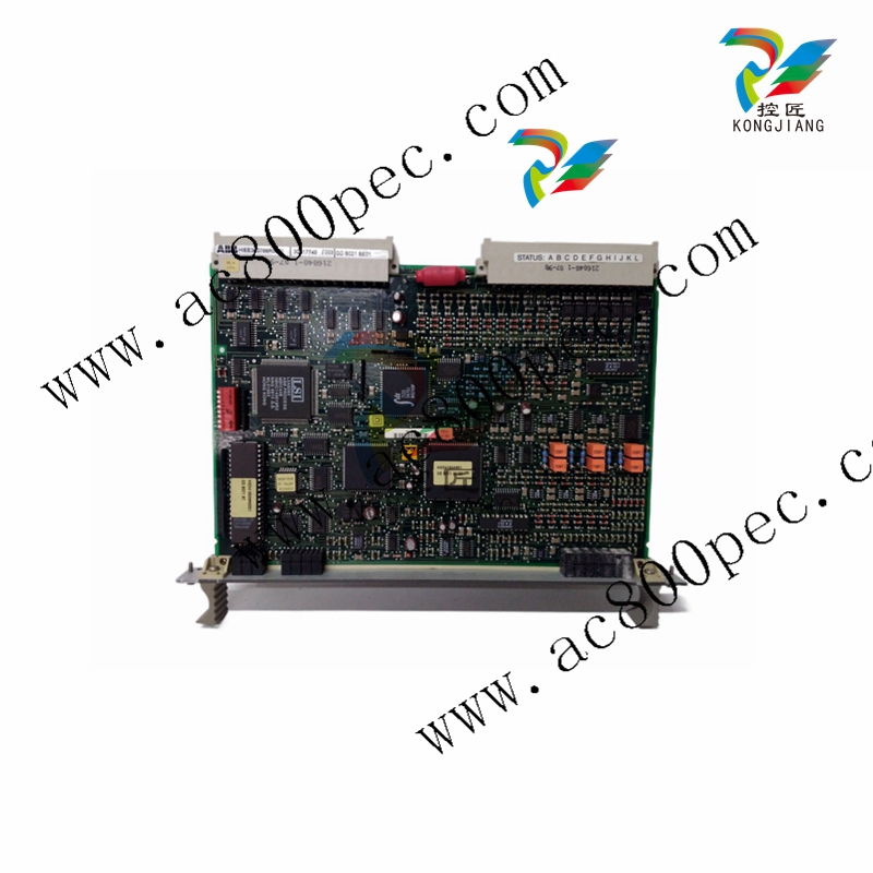
APC is designed to give a flexible, compact and efficient system for
controlling AC- and DC-drives. APC is programmed by using function
blocks.
APC can be supplied with unstable + 24 VDC voltage (connector X1)
that can vary in the range 19 - 30 VDC. Maximum input power
consumption is 15 VA (0.63 A at 24 VDC). This power consumption
includes 2 optional communication boards. APC can handle power
supply failure with max. duration of 5 ms (i.e. voltage is below 19 V).
When the APC board is slid into the CDC board rack, a 64 pole
parallel bus (connector X8) on APC slides into the CDC board rack
bus connector.
AdvantFieldBus 100 (AF 100) is a high speed serial bus (connector
X6), which is used for communication between APCs or between an
APC and an overriding system such as ABB's MasterPiece 90. The
communication board YPK 112A is used to connect the APC to the
AF 100.
RS-485 bus, a 8 pole screw terminal connector X2, is a low speed
serial bus, which is used to connect remote I/O devices and control
panels to the APC. Also other APCs can be connected to each other
via this bus. The bus has to be grounded at one point to the same
ground as the APC. Maximum length of the bus is 300 m.
PC-Link, a standard 9 pole female D-connector X4, can be used to
connect a personal computer to the APC. Physical interface is a
standard non isolated RS-232C (V24) without any handshaking
signals. Recommended maximum length of the cable between APC
and PC is 5 m.
Drive link, an optic link, is used to connect the APC to an AC or a DC
drive. Optical fibres are connected to receiver V32 and transmitter
V33. Communication speed is 1.5 Mbps. Max. length of the fibre is
15 m with standard attenuation cable (Hewlett-Packard HFBR-R or
equivalent) and 25 m with extra low attenuation cable (Hewlett-
Packard HFBR-E or equivalent).
For standard I/O signals there is a 26-pole ribbon cable, connector
X3, on APC. A separate terminal block board SNAT 602 TAC is
always needed for field signal connections. The ribbon cable should
be made as short as possible. Unshielded ribbon cable can be used
provided that the cable is not longer than 2 m.
Power supply section
Composition and type: including connection equipment, rectification equipment, etc., according to different needs can contain a variety of units. According to the function is divided into diode power supply part, regenerative power supply part and resistance braking part, each part contains different unit combinations, applicable to different power ranges .
Introduction of each unit: the function, structure and technical parameters of each unit are introduced in detail, such as the line power supply unit is used to connect the power supply, which contains a variety of electrical equipment; the capacitor bank unit is used to smooth the DC voltage .
Drive section
Power stage type: based on IGBT or GTO power stage, different types are applicable to different power ranges; IGBT power stage is applicable to part of the lower power range, GTO power stage is applicable to the higher power range.
Structure and parameters: the main components of the inverter unit, such as IGBT module, GTO, etc.; the size, weight, overload capacity, cooling requirements and other parameters of different types of drive units are given, as well as the control principle and requirements for the use of parallel inverter units.
Technical Specification
| Frequency: | 50 Hz or 60 Hz ± 3 % |
| Fundamental power factor | 0.97 to 0.99 |
| Total power factor: | 0.93 to 0.95 (theoretical maximum) |
| Efficiency at Rated Power | > 98 % |
| Motor Connection | |
| Voltage, 3 phase: | 0 - 105 % U N |
| Frequency: | 0 to ± 200 Hz |
| Frequency resolution: | 0.01 Hz |
| Static speed control accuracy with pulse encoder feedback: | 0.01 % |
| without feedback (motor slip): | 0.5 - 3 %, can be reduced by slip compensation |
| Dynamic speed control accuracy: | 0.2 - 0.3 % sec at 100 % load step |
| Load capacity | |
| Continuous: | Refer to tables in section 10, inverter sections |
| Overload: | Refer to tables in section 10, inverter sections |
| Switching frequency | |
| IGBT-inverters: | 3 kHz max. |
| GTO-inverters: | 800 Hz max. |
| Field weakening set point range | |
| Frequency: | 10 - 200 Hz |
| Voltage: | 0 - 105 % |
| Torque step rise time: | 5 to 10 ms at 100 % torque reference step (vector control) |
| Acceleration time: | 200 ms - 600 sec. / 100 Hz |
| Deceleration time: | 200 ms - 600 sec. / 100 Hz |
| Enclosure | |
| Degree of protection: Paint colour: | IP21 (MD-cabinet) IP00 (module) light beige, NCS 1704-Y15R |
| Environmental limits | |
| Stationary use: | Ambient air temperature: + 5 to + 40 ° C (+ 45 ° C) |
| Storage: | Ambient air temperature: - 25 to + 55 ° C |
| Transportation: | Ambient air temperature: - 40 to + 70 ° C |
| Cooling method: | dry clean air, integral fan |
| Corrosion severity level of cooling air: | up to G1 as specified in ISA-S71.04 |
| Relative humidity: | ≤ 95 %, no condensation allowed |
| Altitude: | ≤ 1000m ASL, 100 % load capacity |
| Specified Electrical Environmental and Safety Parameters |
| Environmental Conditions | Operating air temperature | +5 ° C to +40 ° C, IEC 68 |
| Storage air temperature | -25 ° C to +55 ° C, IEC 721 |
| Transport air temperature | -40 ° C to +70 ° C, IEC 721 |
| Electrical | Mains voltage variation VDE 0160 excluding short time overvoltage. |
| Conditions | UN = 400 V (380 V, 415 V) ± 10 % |
| | | UN = 500 V (440 V, 460 V) ± 10 % |
| | | UN = 690 V - 10 %, 6 %(575 V, 660 V ± 10 %) |
| Safety | Degree of protection by enclosure IP 21 (optional IP 41), IEC 529 General IEC 439-1 |

- YOKOGAWA
- Reliance
- ADVANCED
- SEW
- ProSoft
- WATLOW
- Kongsberg
- FANUC
- VSD
- DCS
- PLC
- man-machine
- Covid-19
- Energy and Gender
- Energy Access
- Renewable Integration
- Energy Subsidies
- Energy and Water
- Net zero emission
- Energy Security
- Critical Minerals
- A-B
- petroleum
- Mine scale
- Sewage treatment
- cement
- architecture
- Industrial information
- New energy
- Automobile market
- electricity
- Construction site
- HIMA
- ABB
- Rockwell
- Schneider Modicon
- Siemens
- xYCOM
- Yaskawa
- Woodward
- BOSCH Rexroth
- MOOG
- General Electric
- American NI
- Rolls-Royce
- CTI
- Honeywell
- EMERSON
- MAN
- GE
- TRICONEX
- Control Wave
- ALSTOM
- AMAT
- STUDER
- KONGSBERG
- MOTOROLA
- DANAHER MOTION
- Bentley
- Galil
- EATON
- MOLEX
- Triconex
- DEIF
- B&W
- ZYGO
- Aerotech
- DANFOSS
- KOLLMORGEN
- Beijer
- Endress+Hauser
- schneider
- Foxboro
- KB
- REXROTH
- YAMAHA
- Johnson
- Westinghouse
- WAGO
- TOSHIBA
- TEKTRONIX
- BENDER
- BMCM
- SMC
- HITACHI
- HIRSCHMANN
- XP POWER
- Baldor
- Meggitt
- SHINKAWA
- Other Brands
- UniOP
- KUKA
- IBA
- Beckhoff
- ADLINK
-
Beckhoff CX1100-0910 - Power Supply Module
-
Beckhoff C5210-0010 - Communication Module C5210
-
BECKHOFF KL1352 - Bus Terminal SET OF 2 FREE FAST SHIP
-
Beckhoff EL3058 - 8 x analog input single ended 4...20mA 85惟 shunt 12bit
-
Beckoff CX1100-0920 - UPS Module 24VDC (US SELLER) * *
-
BECKHOFF C6920-0000 - C69200000 PLC Moudule
-
Beckhoff CX5120-0115 - CPU controller module CX5120-0115
-
Unknown 15F5C1E-Y50A - Of Frequency Converters
-
Beckhoff AX5118-0000-0200 - Servo Drive HTP0
-
BECKHOFF AX5106-0000-0200 - Servo Drive
-
Beckhoff CX5240-0175 - Module (free) #U2327D YG
-
Beckhoff CP6607-0001-0000 - Compact PC Panel Economy Installation Operator 5,7 "
-
Beckhoff EP3744-0041 - 2022 EP37440041 Module
-
Beckhoff CP6209-0001-0020 - 6.5" PC Touch Screen Control Panel 24VDC
-
Beckhoff CX9020-0111 - /U900 +8x+2xEL3121+1x EL9410+3xEL1008+1x EL2008 Set
-
Beckhoff C6525-1030-0050 - Industrial PC
-
Beckoff CX1100-0920 - UPS Module 24VDC (US SELLER)
-
Beckhoff CX5010-0120 - CX5010 Processor Intel Atom Z510 B24
-
Siemens 6FC5203-0AF04-1BA1 - Operation Panel
-
Beckhoff CX5230-0175 - / 000029724 Embedded PC / Industrial PC on Rail
-
Beckhoff CP3916-0000 - industrielles Anzeige- und Bedienterminal
-
BECKHOFF CX1500-M310 - CX1000-N000 CX1000-0011 CX1000-C00L CX1100-0002 PLC Module
-
Beckhoff EL1872 - 16-channel digital input terminal
-
BECKHOFF EP2318-0001 - module
-
Beckhoff CX9020-0110 - Basic CPU Module
-
Beckhoff EL2564 - EtherCAT Terminal, 4-channel LED output, 5鈥?8VDC, 4A, RGBW
-
Beckhoff CX5130-0155 - /000105637 Automation Embedded PC
-
B&R 400 - Power Control Panel Rev D0 24 VDC
-
Beckhoff CX2020-0155 - module
-
Beckhoff CX9020-0115 - PLC Module
-
BECKHOFF EL6695 - PLC EL 6695
-
BECKHOFF EL7047 - PLC Modules
-
Beckhoff CX1000-0012 - Control HW 2.2 + CX1500-M310 + CX1000-C00L + CX1100-0002+
-
Beckhoff C6920-1039-0030 - control cabinet industrial PC CPU Celeron 1.90 GHz, 2 cores
-
BECKHOFF CX1100-0910 - PLC Module#
-
Beckhoff IL2301-B318-0000 - Coupler Box 4 Channel Digital Input |
-
Beckhoff CX7080 - Module
-
Beckhoff C6930-0060 - Industrial PC
-
Beckhoff CP7902-1060-0000 - Touchscreen 15 " CP7902
-
beckhoff CX9020-0111 - Controller module or UPS
-
Beckhoff CX8091 - PLC Module CX8091
-
Beckhoff C6640-1008-0030 - Control Cabinet Industrial PC
-
BECKHOFF CX1100-0920 - module
-
Beckhoff C9900-M921 - see pictures
-
BECKHOFF CP6829-0001-0000 - Touch Panel
-
BECKHOFF C6930-0060 - Industrial Computer
-
BECKHOFF CX8050 - PLC module
-
Beckhoff CP6202-0021-0020 - Touch Screen #
-
BECKHOFF AM3031-0C20-0000 - SERVO MOTOR
-
Unknown BCH1302N11A1C - Servo motor
-
Beckhoff EL2502 - 2-channel pulse width output terminal
-
Beckhoff EL6731 - Profibus Master / *Rev: 0025
-
Beckhoff CP3918-0010 - Control Panel
-
BECKHOFF CP2915-0010 - [24 MONTH WARRANTY] Control Panel
-
Beckhoff AX5203-0000-0202 - Servo Drive
-
Schneider TSXDSY64T2K - PLC OUTPUT MODULE
-
Beckhoff EP4174-0002 - Module-
-
Beckhoff IL2302-B318-0000 - Profibus Box
-
Beckhoff CP6709-0001-0000 - Touchpanel
-
BECKHOFF CX2030-0123 - Controller
-
Beckhoff CX9020-0111 - Processor Module
-
Beckhoff CX1020-0000 - CX Basic CPU Module
-
Beckhoff AX2003-AS - Servo Drive HTP0
-
Beckhoff C6240-1052-0040 - 4-086-06-3073 Industrial Computer CB1052-0003
-
Beckhoff EL1918 - 8 xTwinSAFE Input
-
Beckhoff AM8072-0R20-0000 - Servomotor
-
BECKHOFF AM8021-1B21-0000 - servo motor #T882 YS
-
Beckhoff EL6224 - 4 X Terminal IO-LINK
-
Beckhoff CX5140-0135 - embedded PC with Intel Atom processor 4 GB HW 3.6
-
Beckhoff CP7201-1000-0000 - Panel PC #
-
Beckhoff CX5130-0121 - Embedded-PC 4GB CPU Module HW 2.5 Industrial PC
-
Beckhoff AM8022-0D41-1002 - Servomotor
-
BECKHOFF CX2030-0130 - Module
-
BECKHOFF EL1872 - 16-channel digital input terminal
-
Unknown GXMMW.A203P33 - 1pc encoder
-
Beckhoff EL6631-0000 - EtherCAT Terminal 2-Port EL 6631
-
BECKHOFF C6925-0030 - Industrial Computer
-
Beckhoff CX8190 - A Module
-
BECKHOFF CX2040-0135 - CX2040-0135/000000927 CPU BASE MODULE i7 2715QE 2.1GHz --
-
BECKHOFF KL6023-0000 - Wireless adapter
-
Saia Burgess PCD7.F700 - PCD7F700 Communication Module
-
Beckhoff CX5130-0112 - CPU Module
-
BECKHOFF CX1020-N010 - CX1020-N000 CX1020-0111 CX1100-0004 EL2008 EL3064 EL4004
-
Beckhoff EP1819-0021 - A Module
-
Beckhoff CX2030-0120 - / 4gb with CX2100 0004
-
B&R X20-XC-0292 - Automation Powerlink Ethernet Bus Controller Module
-
Beckhoff BK3110 - One PLC Module
-
BECKHOFF KL3222 - PLC Module
-
BECKHOFF CX1500-M310 - CX1000-N000 CX1000-0011 CX1000-C00L CX1100-0002 PLC MODULE
-
Beckhoff CP3918-0010 - Control Panel
-
Beckhoff CX2030-0100-1002 - /4GB + CX2100 + CX2550 + CX2500-0060 + SSD
-
Beckhoff EP1816-0008 - PLC Module
-
Beckhoff CX5130-0112 - Module
-
Beckhoff Cx1500-m750 - CPU Hw: 1.4
-
BECKHOFF AX5112-0000-0200 - AX511200000200 Servo Driver
-
Beckhoff EL3751 - EtherCAT Terminal 1 Channel Analog Input Multifunction 24 Bit
-
Beckhoff CX1100-0002 - Power Supply Module
-
Beckhoff CP3916-1016-0010 - Control Panel
-
BECKHOFF CX9001-1101 - #NAME?
-
Beckhoff EP3174-0002 - EtherCAT Box Module
-
Beckhoff C6030-0070 - servo drive
-
Beckhoff CX2020-0120 - /4GB CPU, CX2100-0904, 3x EL6900, EL1904, 16GB Memory
-
BECKHOFF C6110 - BOX-PC 113608
-
BECKHOFF EK1914 - module #P
-
Beckhoff C6140 - Ipox IP-4GVI63 + CH7009A_DVI_TV + SIEMENS A5E00369843 + WD800AAJB
-
Beckhoff CX5020-0111 - controller Good quality
-
BECKHOFF C6015-0010 - / 6559380 ULTRA-COMPACT INDUSTRIAL PC ()
-
Beckhoff AX5203-0000-0200 - PLC module
-
Beckhoff EL2872 - 16-channel digital output terminal
-
BECKHOFF C3640-0000 - Panel Industrial PC 100/240VAC 128MB E0122L
-
Beckhoff CX8031 - Module
-
Beckhoff CX5020-0120-1002 - PLC module#
-
Beckhoff C6140 - M845B + SIEMENS A5E00369843 + C9900_A159_1 + AUTOMATA CAN PCI 1N
-
BECKHOFF AX5112-0000-0200 - Servo Drive*ie
-
B&R ECPA42-01 - Analog Output Module 4-Channel, +/- 10V Output Signal, 20mA Max
-
Beckhoff EL6631-0010 - PLC Module
-
BECKHOFF C6930-0070 - CONTROL CABINET INDUSTRIAL PC
-
BECKHOFF AX5112-0000-0200 - AX511200000200 Servo Driver
-
BECKHOFF EK9000 - Programmable Logic Controller Module EK9000 EK9000
-
BECKHOFF C6920-1028-0000 - Industrial computer
-
Beckhoff CX2030-0120 - controller Module
-
Beckhoff BX8000-0000 - Bus Terminal Controller HW 4.4
-
B&R 3NC154.60-2 - Positioning Module#
-
BECKHOFF CX1020-0122 - PLC module
-
Beckhoff AM3032-0D40-0000 - Servo Motor
-
BECKHOFF CX5020-0111 - CPU Module CX5020-0111
-
Beckhoff CB1051 - G5 Motherboard
-
BECKHOFF KL2641 - 1-channel relay output terminal

K-JIANG

Add: Jimei North Road, Jimei District, Xiamen, Fujian, China
Tell:+86-15305925923