
K-WANG


TEKTRONIX AFG31000 series arbitrary function generator
TEKTRONIX AFG31000 series arbitrary function generator
Product model and core parameters
1. Comparison Table of Model Parameters
Model, bandwidth, sampling rate, number of channels, standard memory, optional memory, pulse generator, bandwidth
AFG31021 25MHz 250MS/s 1 16MS/CH 128MS/CH 20MHz
AFG31022 25MHz 250MS/s 2 16MS/CH 128MS/CH 20MHz
AFG31051 50MHz 1GS/s 1 16MS/CH 128MS/CH 40MHz
AFG31052 50MHz 1GS/s 2 16MS/CH 128MS/CH 40MHz
AFG31101 100MHz 1GS/s 1 16MS/CH 128MS/CH 80MHz
AFG31102 100MHz 1GS/s 2 16MS/CH 128MS/CH 80MHz
AFG31151 150MHz 2GS/s 1 16MS/CH 128MS/CH 120MHz
AFG31152 150MHz 2GS/s 2 16MS/CH 128MS/CH 120MHz
AFG31251 250MHz 2GS/s 1 16MS/CH 128MS/CH 160MHz
AFG31252 250MHz 2GS/s 2 16MS/CH 128MS/CH 160MHz
2. General technical characteristics
Vertical resolution: 14 bits, ensuring waveform accuracy.
Output impedance: default 50 Ω, can be set to 1 Ω~10k Ω (resolution 1 Ω) or Infinity (>10k Ω).
Modulation types: Supports AM (amplitude modulation), FM (frequency modulation), PM (phase modulation), FSK (frequency shift keying), PWM (pulse width modulation).
Environmental adaptability: working temperature of 0 ℃~40 ℃, humidity of 5%~85% RH, working altitude of 3000m.
Safety regulations and operating taboos
1. Core security principles
Only for professional operation: Only personnel with high voltage/high frequency testing qualifications are allowed to operate, and non professionals are prohibited from contacting.
System level security: If connecting to a large system, it is necessary to comply with the security manuals of other components of the system.
Preoperative examination: Before use, verify that the device is functioning properly with a known signal source and prohibit its use for detecting dangerous voltages.
2. Key operations for preventing electric shock and fire prevention
(1) Power supply and grounding
Use designated power cords (must comply with local certification), and do not mix power cords from other devices.
The equipment is grounded through the power cord, and the grounding conductor must be connected to the ground. It is forbidden to disconnect the grounding connection.
Confirm that the power supply voltage matches the rated value of the equipment (such as 100V~240V AC) before powering on.
(2) Connection/disconnection sequence
Operation type, step purpose
Connect circuit 1. Connect the probe output to the measuring instrument → 2 Connect the probe reference terminal to the tested circuit → 3 Connect the probe input to avoid electric shock or equipment damage caused by live plugging and unplugging
Disconnect circuit 1. Disconnect probe input and reference terminal → 2 Disconnect the probe from the instrument to prevent residual voltage shock
(3) Taboos on Environment and Equipment Status
Do not use in damp, explosive, and dusty environments, and do not operate without cover plates/panels (exposing high-voltage circuits).
If the equipment falls, gets wet, or is suspected of damage, authorized personnel must inspect it before use, and it is prohibited to disassemble it by oneself.
Do not touch the exposed circuit when powered on, and keep the probe body and output line away from the tested circuit.
Remote control interface and instruction system
1. Interface configuration
(1) GPIB interface
Requirements:
Each device must have a unique address (1-30) and must not be duplicated;
The bus can connect up to 15 devices, with a total cable length of ≤ 20m and at least 1 device per 2m;
Power on devices account for ≥ 67%, support star/linear topology, and prohibit parallel/ring topology.
Address setting: Enter the address through the panel "Utility → I/O Interface → GPIB Address" (* RST command cannot initialize the address).
(2) VISA interface
TekVISA software (official website download) needs to be installed, supporting GPIB, RS-232, Ethernet remote control, and complying with VISA 2.2 standard.
Applicable development environment: Windows system, supporting ADE (Application Development Environment) such as LabVIEW and VB.
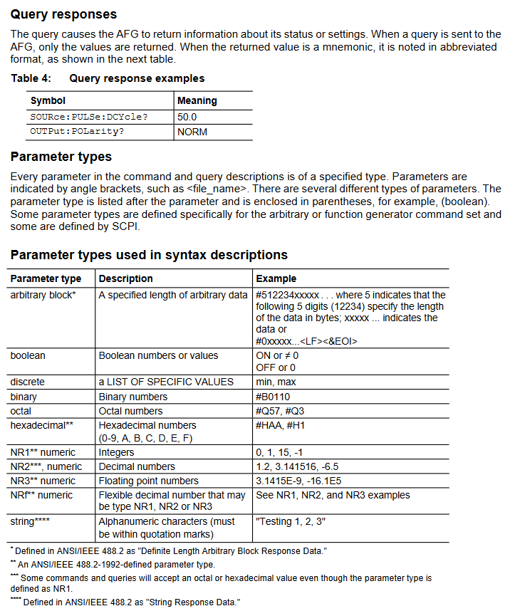
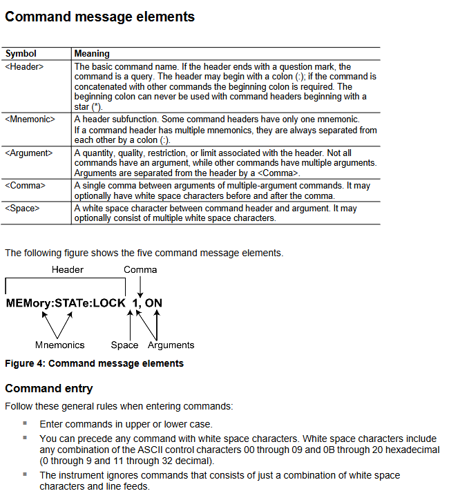
2. Instruction system and syntax
(1) Instruction classification
Example Function of Instruction Type
IEEE 488.2 General Command * CAL? 、 *CLS, * RST self calibration, clear register, reset
SCPI command SOURce1: FUNCTION SIN, OUTPut1: STATe ON. Set the waveform of channel 1 to sine and enable the output of channel 1
(2) Core Grammar Rules
Abbreviation: Commands can be abbreviated (uppercase is required, lowercase can be omitted), such as DISPlay: BRIGhtness can be abbreviated as DISP: BRIG.
Chain command: Multiple commands are separated by semicolons, and prefixes can be omitted for the same root node, such as TRIGger: CLOPe POS; SOURce SIN (assuming the trigger slope is positive and the source waveform is sine).
SI units: support voltage (V/mV), frequency (Hz/kHz/MHz), time (s/ms/μ s/ns), etc., such as Frequency 10MHz (assuming frequency 10MHz).
Parameter type: Supports Boolean values (ON/OFF), numerical values (NR1/NR2/NR3), and strings (quotation marks required), such as MMEMory: DELete "U:/TEST. TFWX" (remove the TEST. TFWX file from USB).
Detailed explanation of core functions and instructions
1. Waveform generation and output control
(1) Waveform type and parameter settings
Supporting waveforms: 13 types including sine (SINusoid), square wave (SQUare), pulse (PULSe), ramp (RAMP), noise (PRNoise), arbitrary wave (EMEMory/EFILe), etc.
Example of Key Instructions:
Let the waveform of channel 1 be sine: SOURce1: FUNCTION SIN
Assuming a frequency of 10kHz: SURce1: Frequency 10kHz
Set amplitude to 2Vpp: SURce1: VOLTage: Amplitude 2VPP
Set offset 1V: SURce1: VOLTage: OFFSet 1V
(2) Output control
Turn on/off output: OUTPut1: STATe ON/OFF
Output polarity reversal: OUTPut1: Polarity Inverted (default NORMAL)
Output impedance setting: OUTPut1: Impedance 50OHM (default 50 Ω, can be set to 1 Ω~10k Ω)
2. Modulation function (AM/FM/PM, etc.)
Taking AM (amplitude modulation) as an example, the key instructions are as follows:
Example of functional instructions
Set modulation depth SOURce1: AM: DEPTh SOURce1: AM: DEPTh 50PCT (50% depth)
Set the internal modulation frequency SOURce1: AM: INTernal: FREQuency SOURce1: AM: INTernal: FREQuency 1kHz
Set modulation source SOURce1: AM: SOURce1: AM: SOURce INTernal (internal source)
Turn on AM SOURce1: AM: STATe SOURce1: AM: STATe ON
3. Sequence control (advanced mode)
Support defining 256 sequence elements to achieve waveform looping, jumping, and waiting for triggering. Core instructions:
New sequence: SEQueen: NEW
Set sequence length (10 elements): SEQuence: LENGth 10
Let element 1 loop 100 times: SEQuence: ELEM1: LOOP: COUNT 100
After triggering element 1, jump to element 6: SEQuence: ELEM1: GOTO: INDex 6; GOTO:STATe ON
Running sequence: SEQControl: RUN: IMMediate
4. Data storage and management
(1) Virtual Disk Definition
Disk identification, storage location, permission usage
U: USB flash storage for reading and writing user waveforms/settings files
M: Internal flash read-write storage commonly used waveforms/settings
P: Internal predefined area read-only storage factory preset waveforms (such as sine and square waves)
(2) Store/load instructions
Save channel 1 waveform to USB: MMEMory: STORe: TRACe EMEMory1, "U:/WAVE1. TFWX"
Loading settings from USB to memory 1: MMEMory: LOAD: STATe 1, "U:/SET1. TFS"
Delete USB file: MMEMory: DELete "U:/OLD. TFWX"
Status and Event Management
1. Status register system
Compliant with IEEE 488.2 and SCPI standards, the core registers are as follows:
Meaning of register name function key bits
Status Byte Register (SBR) summarizes device status OSB (operational status), ESB (event status), MAV (message available)
The Standard Event Status Register (SESR) records core events OPC (operation completed), CME (command error), EXE (execution error)
The operating condition register (OCR) records the operating status CAL (calibration in progress), SWE (scanning in progress), WTRIG (waiting for trigger)
2. Error code system
Error codes are divided into "standard errors" (-100~-499) and "device specific errors" (1~32767). Common examples include:
Error code type description
-100 command errors command syntax errors (such as spelling errors)
-222 execution error parameter out of range (e.g. frequency set to 1000MHz, exceeding the upper limit of 250MHz)
-350 device error error queue overflow (more than 64 events)
1101 calibration error CH1 internal offset calibration failed
2305 self-test error CH1 output gain self-test failed
3. Error query
Search for the next error: SYSTem: ERRor: NEXT? The return format is -222, "Data out of range"
Maintenance and troubleshooting
1. Maintain standards
Cleaning: Wipe the outer surface with a dry lint free cloth or 75% isopropanol. Do not use water/solvents/abrasives, and do not allow moisture to enter the interior of the equipment.
Repair restriction: There are no user repairable parts, and only DC offset can be adjusted for serial numbers C019999 and below. Other faults need to be returned to the factory.
2. Common fault handling
Troubleshooting steps for possible causes of fault phenomena
No waveform output turned on, parameter out of range 1. Execute OUTPut1: STATe? Confirm the output status; 2. Check if the frequency/amplitude is within the device range
GPIB no response address conflict, cable fault 1. Confirm that GPIB address is unique; 2. Replace GPIB cable; 3. Restart the device and controller
Calibration failed due to excessive temperature and humidity in the environment, hardware malfunction. 1. Confirm that the environment is 0 ℃~40 ℃/5%~85% RH. 2. Execute DIAGnostic? Self inspection; 3. If errors 1101-1216 are reported, return to the factory for repair
- YOKOGAWA
- Reliance
- ADVANCED
- SEW
- ProSoft
- WATLOW
- Kongsberg
- FANUC
- VSD
- DCS
- PLC
- man-machine
- Covid-19
- Energy and Gender
- Energy Access
- Renewable Integration
- Energy Subsidies
- Energy and Water
- Net zero emission
- Energy Security
- Critical Minerals
- A-B
- petroleum
- Mine scale
- Sewage treatment
- cement
- architecture
- Industrial information
- New energy
- Automobile market
- electricity
- Construction site
- HIMA
- ABB
- Rockwell
- Schneider Modicon
- Siemens
- xYCOM
- Yaskawa
- Woodward
- BOSCH Rexroth
- MOOG
- General Electric
- American NI
- Rolls-Royce
- CTI
- Honeywell
- EMERSON
- MAN
- GE
- TRICONEX
- Control Wave
- ALSTOM
- AMAT
- STUDER
- KONGSBERG
- MOTOROLA
- DANAHER MOTION
- Bentley
- Galil
- EATON
- MOLEX
- Triconex
- DEIF
- B&W
- ZYGO
- Aerotech
- DANFOSS
- KOLLMORGEN
- Beijer
- Endress+Hauser
- schneider
- Foxboro
- KB
- REXROTH
- YAMAHA
- Johnson
- Westinghouse
- WAGO
- TOSHIBA
- TEKTRONIX
- BENDER
- BMCM
- SMC
- HITACHI
- HIRSCHMANN
- XP POWER
- Baldor
- Meggitt
- SHINKAWA
- Other Brands
- UniOP
- KUKA
- IBA
- Beckhoff
-
ADLINK CPCI-6860A - 51-31310-OB10 industrial motherboard CompactPCI SBC
-
ADLINK AmITX-SL-G-H110 - 51-7A104-0A30 Mini-ITX Industrial Motherboard
-
ADLINK PXI-2005-003 - CPCI Industrial PC Data Acquisition Card Multi-Function DAQ
-
ADLINK DININ-814M - 51-14032-0A3D SCSI-100P cable connection Interface Terminal Board
-
ADLINK CPCI-3920NA/C2D15/M1G - 3U CompactPCI Intel Core 2 Duo Single Board Computer
-
ADLINK PCIE-8560 - 51-18014-0A20 Communication Card High Speed DAQ
-
ADLINK PCI-C154+ - Motion Control Card 4-axis Motion Controller Board
-
ADLINK PCI-RTV24 - image capture card Analog Video Frame Grabber
-
ADLINK NuPRO-842LV/P - 51-41360-0B30 Industrial Motherboard CPU Board
-
ADLINK cBP-3208/3208R - CPCI Board 3U 8-Slot CompactPCI Backplane
-
ADLINK PCI-8164 - 4-Axis Motion Controller PCI Card 51-12406-0A40
-
ADLINK PCIe-GIE64+ - 4-CH GigE Vision PoE+ Frame Grabber Video Capture Card
-
ADLINK CPCI-6860 / 6860A - CompactPCI Dual Xeon Single Board Computer
-
ADLINK IEC-915GV - REV 1.1 Industrial motherboard CPU Board
-
ADLINK ND-6520 - Technology RS-232 to RS-422RS-485 Converter NuDAM Module
-
ADLINK RTV-24 / PCI-MP4S - 51-12519-1C30 4-Channel Real Time Video Capture Board
-
ADLINK cPCI-6910 / cPCI-6910AM/M1G - cPCI-6910AM/DXL16/M1G/S80G(G)-3120 BOARD CompactPCI SBC
-
ADLINK NUPRO-A40H - Linghua 51-41807-1A30 Industrial Control Computer Motherboard
-
ADLINK USB-3488A - USB to GPIB INTERFACE USB-3488A(G) Controller Module
-
ADLINK PCI-8134A - motion control card 4-Axis Controller Card
-
ADLINK PCI-7432 - Board 32-Channel input / 32-output Isolated Digital I/O PCI Card
-
ADLINK PCI-8134A - 51-12421-0A10 motion controller card tested
-
ADLINK LPCIe-7230 - 32 CH Isolated Input/output Card 2 Interrupts Low Profile PCIe
-
ADLINK NuPRO-E340 - industrial computer motherboard 51-47807-0A30 PICMG 1.3 SHB
-
ADLINK PCI-7434 - High-speed Digital Acquisition Card 64-CH Isolated DO Card
-
ADLINK NuPRO-E330 - 51-41805-0A20 Indsutrial Board SHB Single Board Computer
-
ADLINK PCI-7248 - OPTO-22 48 CHANNEL DIO DIGITAL TTL/DTL I/O 51-12006-0A40 GP
-
ADLINK PCI-8134 - Motion control card 4-Axis Controller Card
-
ADLINK AMP-208C - Movimiento Control Tarjeta 51-12420-1A20 W/Expansión & Breakout
-
ADLINK PCI-8164 - 51-12406-0A40 PCB Board 4-Axis Motion Controller Card
-
ADLINK DIN-68Y-SGII / DIN-68M-J3A - Terminal Board Connector Interface Block
-
ADLINK PCIe-7432 - Technology 51-18402-0A10 PCIe Card With High Input Range
-
ADLINK PCI-8144 / PCI-8144N - Motion control card 4-Axis Stepper Controller Card
-
ADLINK HSL-HUB3/REPEATER - HIGH SPEED LINK EXTENSION MODULES Distributed Hub Module
-
ADLINK ND-6017 - Data Logging + Acquisition 8CH A/D input Mod NuDAM Module
-
ADLINK LPCIe-7250 - data acquisition card Low Profile 8-CH Relay Output Card
-
ADLINK PCI-7432 - I/O card 64-CH Isolated Digital Input Output PCI Card
-
ADLINK IMB-M43H - industrial control computer motherboard Q87 Chip Micro-ATX
-
ADLINK MP-C154 - Motion control Card 4-Axis Motion Controller Board
-
ADLINK PCI-RTV24 - image capture card Video Frame Grabber Card
-
ADLINK PCI-7250 - 8-CH Relay Output & 8-CH Isolated DI Card
-
ADLINK PCI-6308V - 8-CH 12-Bit Isolated Analog Output PCI Card PCB-I-E-1148=6EX2
-
ADLINK PCI-7248 - capture card 48-CH Opto-22 Compatible DIO Card
-
ADLINK HSL-AI16A02-M-VV - Analog Input Output Distributed Module
-
ADLINK NuPRO-A301 - Rev:1.4 NUPRO-A301 PICMG Full-Size Single Board Computer
-
ADLINK PCI-6208V-GL - 8-CH Voltage Analog Output PCI Card
-
ADLINK PCI-8134A - 51-12421-0A10 4-Axis Motion Controller Card
-
ADLINK MNET-S23 - TECHNOLOGY MNET S23 - SERVO DRIVER CONTROL MODULE
-
ADLINK M-342 - ATX I3 I5 I7 Q67 Industrial Motherboard
-
ADLINK NUPRO-780 - Industrial Motherboard CPU Board PICMG SBC
-
ADLINK MP-C154 / MP-C152 - 4-Axis Motion Control Card Pulse-Train Controller
-
ADLINK NuPRO-935A/LV10B0 - Motherboard 51-41802-0A10 GP w/RAM Industrial Control Board
-
ADLINK MP-C154 - Motion control card 4-Axis Motion Controller Mainboard
-
ADLINK PCI-7250 - PCI Acquisition Card 8-CH Relay Output Isolated DI Card
-
ADLINK ACL-7124 - Technology Inc.24 DIO Card Digital Input Output Card
-
ADLINK PCI-8554 A2 - Timer/Counter Data Acquisition Card
-
ADLINK DIN-825-GP4 - Terminal Block Interface Board Breakout Module
-
ADLINK NuPR0-761 - REV:1.1 Industrial motherboard Full-Size PICMG SBC
-
ADLINK MXE-1401/M8G (G) - Matrix Fanless Embedded Computer Industrial PC
-
ADLINK HSL-DI16DO16-UD-NN - Digital 16 Channel I/O Mod Distributed I/O Module
-
ADLINK ND6520 - NUDAM INTELLIGENT DA&C MODULE RS232-RS-422/RS485 CONVERTOR
-
ADLINK NUPRO-761 - REV:1.1 Industrial Motherboard CPU Board
-
ADLINK AMP-208C - Motion Control Card 51-12420-1A20 DSP-based 8-axis
-
ADLINK NuPRO-A301REV 1.4 - with packaging industrial computer motherboard PICMG SBC
-
ADLINK PCM-9112+ - 51-12300-0A2 industrial motherboard Multi-Function DAQ PC/104 Module
-
ADLINK PCM-7250+ - 8-CH Relay Outputs & 8-CH Isolated DI Module PC/104
-
ADLINK PCI-RTV24 - Image capture card Analog Video Frame Grabber
-
ADLINK PCI-8134 - Motion Controller PCI Card 4-Axis Controller Board
-
ADLINK PCI-7432 - Isolated Digital I/O PCI Card
-
ADLINK PCI-8554 A2 - acquisition card Timer/Counter Card
-
ADLINK PCI-8132 - Rev.A2 2-Axis Servo & Stepper Motion Controller Card
-
ADLINK PCI-8132 - Data Acquisition card 2-Axis Motion Controller Card
-
ADLINK EBP-13E4 - 51-46703-0A30 Industrial Backplane Board Passive Backplane
-
ADLINK PCI-800L - Electronic Card Interface Controller Card
-
ADLINK PCIe-GIE72 - 51-18531-0A10 PCB Board GigE Vision Frame Grabber
-
ADLINK DAQ-2010(G)-OOBO - Simultaneous-Sampling Multi-Function DAQ Card
-
ADLINK PCI-9112 - REV.B1 Multifunction DAQ Card Data Acquisition Card
-
ADLINK PCI-7230 - 51-12003-DA60 32-CH Isolated Digital I/O Card
-
ADLINK PCI-7432 - Data Acquisition Card Isolated Digital I/O PCI Card
-
ADLINK ETX-AT-N270-18/LXE - 51-71111-0A20 ETX CPU Module Motherboard
-
ADLINK HSL-DI32-UD-N - DIGITAL INPUT 32 POINTS MODULE Distributed I/O
-
ADLINK AMP-204C - Motion Control card DSP-Based 4-Axis Advanced Controller
-
ADLINK MNET-4XMOG-0050 - Four-axis Motion Controller Distributed Motion Module
-
ADLINK AMP-204C - Motion control card DSP-Based 4-Axis Pulse-Train Controller
-
ADLINK PCI-7442 - Switch card 64-Channel Datalogging & Acquisition Card
-
ADLINK M-302 - Industrial control motherboard ATX PC Board
-
ADLINK NUPRO-852 / NUPRO-852LV - Industrial motherboard Single Board Computer
-
ADLINK PCI-8134 - REV.B1. 4-Axis Motion Controller Card
-
ADLINK PCI-GIE62 + - 51-18502-0A20 2-CH GigE Vision Frame Grabber PoE Card
-
ADLINK PCI-MPG24 - 51-12523-0B20 MPEG4 Card Video Compression Hardware
-
ADLINK HSL-TB32-M-DIN - 32-CH I/O TERMINAL W/ HSL-AI16AO2-M-VV MODULE
-
ADLINK PCI-M114-GL - PCB Ver 2.1 Motion Controller Axis Card
-
ADLINK IMB-M40H - SYM76996H61 motherboard Industrial Computer Mainboard
-
ADLINK NUPRO-A40H - 51-41807-1A20 industrial control motherboard H61 Chip
-
ADLINK PCI-M114-GL - Axis Card Data Acquisition Card PCB VER2.2 Motion Controller
-
ADLINK PCI-8134 - Motion Controller PCI Card 4-Axis Controller Board
-
ADLINK PCI-8102 - Motion control card 2-Axis Servo & Stepper Controller
-
ADLINK NuPRO-841REV:3.0 - motherboard Industrial Control PC Board
-
ADLINK HSL-TB32-U-DIN REV A1 - Breakout Terminal Board Field I/O Module
-
ADLINK AMP-204C - Motion Control card DSP-Based 4-Axis Pulse-Train Controller
-
ADLINK NUPRO-A40H - 51-41807-1A20 industrial control motherboard H61 PC Board
-
ADLINK PCI-6308A / PCI-6308V - 51-12202-0A50 Isolated Analog Output Card
-
ADLINK AMP-204C - DSP-Based 4-Axis Advanced Pulse-Train Motion Controller
-
ADLINK PCI-7434 - Technology 64-Channel Isolated Digital I/O PCI Cards
-
ADLINK CPCI-6840 / CPCI-6840V / PM16/M1G-12G0 - CompactPCI Single Board Computer CPU Module
-
ADLINK PCIE-GIE74 - Motherboard Video Capture Card 51-18531-0A10 Frame Grabber
-
ADLINK NuPRO-E330 - industrial computer equipment motherboard Control Mainboard
-
ADLINK AMP-208C / 51-12420-1A20 - Motion Control Card W/ Expansion & Breakout Board
-
ADLINK HPCI-14S12U - industrial computer baseboard Passive Backplane 14 Slots
-
ADLINK PCI-8164 - 4-Axis Motion Controller PCI Card W/ 1x Cable, 1x Breakout Box
-
ADLINK PCIe-RTV24 - 51-18016-0A20 Image Acquisition Video Capture Card
-
ADLINK M-342 - 5 PCI ATX Motherboard Industrial PC Mainboard
-
ADLINK PCI-FIW64 - 4/2 Channel IEEE1394B Image Capture Card FireWire Frame Grabber
-
ADLINK PCI-7432 - digital IO card 64-CH Isolated Digital Input Output Card
-
ADLINK 51-12001-0C20 - Circuit Board PCI-7200 Data Acquisition Controller Card
-
ADLINK PXI-3920 - PXI 3U cPCI Industrial Controller Embedded System CPU Board
-
ADLINK NuPRO-841REV:2.0 - motherboard Industrial Control PC Board
-
ADLINK NuPro-E330 - 51-41805-0A20 PCB Industrial Control Computer Motherboard
-
ADLINK PCI-RTV24 - Image capture card Analog Video Frame Grabber
-
ADLINK PCI-7442 - Switch card 64-Channel Datalogging & Acquisition Card
-
ADLINK HPX-13S4 - device baseboard Passive Backplane Riser Card
-
ADLINK PCI-9112 REV A.1 - Multi Function DA&C Board Data Acquisition Card
-
ADLINK PCI-7248 - 51-12006-0A40 Card Control 48-CH Digital I/O Module
-
ADLINK CPCI-6860 / 6860A - motherboard CompactPCI Dual Xeon Single Board Computer
-
ADLINK DPAC-3020-11(G) - Embedded PC Automation Controller Machine Control Board
-
ADLINK NuPRO-841 REV:1.0 - industrial control motherboard CPU Board
-
ADLINK MNET-4XMOG-0050 - Four-axis Motion Controller MNET Motion Control Card
-
ADLINK ETX-AT-N270-18/LXE - 51-71111-0A20 ETX CPU Module Motherboard

K-JIANG

Add: Jimei North Road, Jimei District, Xiamen, Fujian, China
Tell:+86-15305925923