
K-WANG
+086-15305925923
Service expert in industrial control field!


Product
Article
NameDescriptionContent
Adequate Inventory, Timely Service
pursuit of excellence


Ship control system
Equipment control system
Power monitoring system
Current position:
新闻动态
newS
Brand
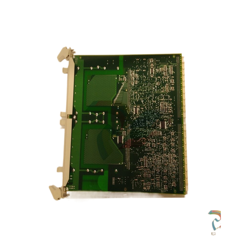
ABB AI830A DCS programming analog input unit
ABB AI830A DCS programming analog input unit
ABB AI830A DCS programming analog input unit
External +24 V DC power supply for the RMIO board is recommended if• the application requires a fast start after connecting the input power supply
• fieldbus communication is required when the input power supply is disconnected.
The RMIO board can be supplied from an external power source via terminal X23 or
X34 or via both X23 and X34. The internal power supply to terminal X34 can be left
connected when using terminal X23.
WARNING! If the RMIO board is supplied from an external power source via
terminal X34, the loose end of the cable removed from the RMIO board terminal
must be secured mechanically to a location where it cannot come into contact with
electrical parts. If the screw terminal plug of the cable is removed, the wire ends
must be individually insulated.
Parameter settings
In Standard Control Program, set parameter 16.9 CTRL BOARD SUPPLY to
EXTERNAL 24V if the RMIO board is powered from an external supply
External control connections (non-US)
External control cable connections to the RMIO board for the ACS800 Standard
Control Program (Factory Macro) are shown below. For external control connections
of other control macros and programs, see the appropriate firmware manual.
X2* RMIO
X20 X20
1 1 VREF- Reference voltage -10 VDC, 1 kohm < RL <
2 2 AGND 10 kohm
X21 X21
1 1 VREF+ Reference voltage 10 VDC, 1 kohm < RL <
10 kohm 2 2 AGND
3 3 AI1+ Speed reference 0(2) ... 10 V, Rin =
200 kohm 4 4 AI1-
5 5 AI2+ By default, not in use. 0(4) ... 20 mA, Rin =
100 ohm 6 6 AI2-
7 7 AI3+ By default, not in use. 0(4) ... 20 mA, Rin =
100 ohm 8 8 AI3-
9 9 AO1+ Motor speed 0(4)...20 mA 0...motor nom.
speed, RL < 700 ohm 10 10 AO1-
11 11 AO2+ Output current 0(4)...20 mA 0...motor
nom. current, RL < 700 ohm 12 12 AO2-
X22 X22
1 1 DI1 Stop/Start
2 2 DI2 Forward/Reverse 1)
3 3 DI3 Not in use
4 4 DI4 Acceleration & deceleration select 2)
5 5 DI5 Constant speed select 3)
6 6 DI6 Constant speed select 3)
7 7 +24VD +24 V DC max. 100 mA
8 8 +24VD
9 9 DGND1 Digital ground
10 10 DGND2 Digital ground
11 11 DIIL Start interlock (0 = stop) 4)
X23 X23
1 1 +24V Auxiliary voltage output and input, non isolated, 24 V DC 250 mA 5) 2 2 GND
X25 X25
1 1 RO1 Relay output 1: ready
2 2 RO1
3 3 RO1
X26 X26
1 1 RO2 Relay output 2: running
2 2 RO2
3 3 RO2
X27 X27
1 1 RO3 Relay output 3: fault (-1)
2 2 RO3
3 3 RO3
External control connections (US)
External control cable connections to the RMIO board for the ACS800 Standard
Control Program (Factory Macro US version) are shown below. For external control
connections of other control macros and programs, see the appropriate firmware
manual.
X2* RMIO
X20 X20
1 1 VREF- Reference voltage -10 VDC, 1 kohm < RL <
2 2 AGND 10 kohm
X21 X21
1 1 VREF+ Reference voltage 10 VDC, 1 kohm < RL <
10 kohm 2 2 AGND
3 3 AI1+ Speed reference 0(2) ... 10 V, Rin =
200 kohm 4 4 AI1-
5 5 AI2+ By default, not in use. 0(4) ... 20 mA, Rin =
100 ohm 6 6 AI2-
7 7 AI3+ By default, not in use. 0(4) ... 20 mA, Rin =
100 ohm 8 8 AI3-
9 9 AO1+ Motor speed 0(4)...20 mA 0...motor nom.
speed, RL < 700 ohm 10 10 AO1-
11 11 AO2+ Output current 0(4)...20 mA 0...motor
nom. current, RL < 700 ohm 12 12 AO2-
X22 X22
1 1 DI1 Start ( )
2 2 DI2 Stop ( )
3 3 DI3 Forward/Reverse 1)
4 4 DI4 Acceleration & deceleration select 2)
5 5 DI5 Constant speed select 3)
6 6 DI6 Constant speed select 3)
7 7 +24VD +24 VDC max. 100 mA
8 8 +24VD
9 9 DGND1 Digital ground
10 10 DGND2 Digital ground
11 11 DIIL Start interlock (0 = stop) 4)
X23 X23
1 1 +24V Auxiliary voltage output and input, non isolated, 24 VDC 250 mA 5) 2 2 GND
X25 X25
1 1 RO1 Relay output 1: ready
2 2 RO1
3 3 RO1
X26 X26
1 1 RO2 Relay output 2: running
2 2 RO2
3 3 RO2
X27 X27
1 1 RO3 Relay output 3: fault (-1)
2 2 RO3
3 3 RO3
Fault
A
rpm
RMIO
Terminal block size:
cables 0.3 to 2.5 mm2 (22 to 14 AWG)
Tightening torque:
0.2 to 0.4 Nm (0.2 to 0.3 lbf ft)
* optional terminal block in ACS800-U2
and ACS800-U7
1) Only effective if par. 10.03 is set to
REQUEST by the user.
2) 0 = open, 1 = closed
3) See par. group 12 CONSTANT
SPEEDS.
4) See parameter 21.09 START INTRL
FUNC.
5) Total maximum current shared
between this output and optional
modules installed on the board.
- YOKOGAWA
- Reliance
- ADVANCED
- SEW
- ProSoft
- WATLOW
- Kongsberg
- FANUC
- VSD
- DCS
- PLC
- man-machine
- Covid-19
- Energy and Gender
- Energy Access
- Renewable Integration
- Energy Subsidies
- Energy and Water
- Net zero emission
- Energy Security
- Critical Minerals
- A-B
- petroleum
- Mine scale
- Sewage treatment
- cement
- architecture
- Industrial information
- New energy
- Automobile market
- electricity
- Construction site
- HIMA
- ABB
- Rockwell
- Schneider Modicon
- Siemens
- xYCOM
- Yaskawa
- Woodward
- BOSCH Rexroth
- MOOG
- General Electric
- American NI
- Rolls-Royce
- CTI
- Honeywell
- EMERSON
- MAN
- GE
- TRICONEX
- Control Wave
- ALSTOM
- AMAT
- STUDER
- KONGSBERG
- MOTOROLA
- DANAHER MOTION
- Bentley
- Galil
- EATON
- MOLEX
- Triconex
- DEIF
- B&W
- ZYGO
- Aerotech
- DANFOSS
- KOLLMORGEN
- Beijer
- Endress+Hauser
- schneider
- Foxboro
- KB
- REXROTH
- YAMAHA
- Johnson
- Westinghouse
- WAGO
- TOSHIBA
- TEKTRONIX
- BENDER
- BMCM
- SMC
- HITACHI
- HIRSCHMANN
- XP POWER
- Baldor
- Meggitt
- SHINKAWA
- Other Brands
- UniOP
- KUKA
- IBA
- Beckhoff
- ADLINK
51
-
Beckhoff CP7232-0001-0030 - Control Panel PC HMI
-
Beckhoff CX5020-0122 - Embedded PC CPU Module
-
Beckhoff AM8043-0H10-0000 - Rotary Synchronous Servo Motor
-
Beckhoff CP3924-0010 - Multitouch Control Panel HMI
-
Beckhoff CX9020-0110-1005 - Embedded PC Basic CPU Module
-
Beckhoff BK9105 - EtherNet/IP Bus Coupler
-
Beckhoff CX1500-M310 - Profibus Master Fieldbus Extension Module
-
Beckhoff CX1500-M510 - PROFIBUS Master Fieldbus Extension Module
-
Beckhoff CP9922.0 - TTL-TX Display Transmitter Card
-
Beckhoff CP9010_1 - ISA Slot Interface Card
-
Beckhoff NRL75-DC30S15B - LCD Inverter Board
-
Beckhoff LTD121C30S - Toshiba LCD Display Panel
-
Beckhoff CP7732-1207-0030 - Operating Terminal Panel PC HMI
-
Beckhoff C5102-0010 - Rackmount Industrial Computer PC5000
-
Beckhoff C6015-0010 - Ultra-Compact Industrial PC
-
Beckhoff CB1056-0001 - Industrial PC Motherboard Mainboard
-
Beckhoff AX5103 - Digital Compact Servo Amplifier 1 Axis
-
Beckhoff AM8052-0J00-9000 - Rotary Synchronous Servo Motor
-
Beckhoff CP7932-0002-0000 - Control Panel HMI Display
-
Beckhoff CB1061-0001 - Industrial PC Motherboard Mainboard
-
Beckhoff C5102-0060 - 19-inch Rackmount Industrial PC
-
Beckhoff EL7342 - 2 Channel DC Motor Motion Interface EtherCAT Terminal
-
Beckhoff CX5120-0135 - Embedded PC CPU Module Intel Atom
-
Beckhoff CB1061-G4 - Industrial PC Motherboard Mainboard
-
Beckhoff CX50100121 - Embedded PC CPU Module
-
Beckhoff CX1030-0013-1002 - Basic CPU Module Intel Pentium M
-
Beckhoff CP7802-1075-0010 - Control Panel Touch Screen HMI
-
Beckhoff AM8023-0E20-0000 - Rotary Synchronous Servo Motor
-
Beckhoff EL5032 - 2 Channel Encoder Interface EnDAT EtherCAT Terminal
-
Beckhoff CX5130-0175 - Embedded PC CPU Module Intel Atom
-
Beckhoff CA4040-0000 - PCI Ethernet Network Board
-
Beckhoff C3340 - Panel PC Industrial Workstation
-
Beckhoff EL3068 - 8 Channel Analog Input EtherCAT Terminal 0-10V
-
Beckhoff EL1889 - 16 Channel Digital Input EtherCAT Terminal
-
Beckhoff C6640-0050 - Control Cabinet Industrial PC Intel Core i7
-
Beckhoff PC MIC 3230 TP - Industrial Panel PC Touch Screen
-
Beckhoff CX2040-0135 - Embedded PC Industrial CPU Module
-
Beckhoff CP6202-1020-0010 - Built-in Panel PC HMI
-
Beckhoff KL3001 - 1 Channel Analog Input Bus Terminal 0-10V
-
Beckhoff C6920-1047-0030 - Control Cabinet Industrial PC
-
Beckhoff CX5140-0122 - Embedded PC CPU Module
-
Beckhoff AX5106-0000-0200 - Digital Compact Servo Amplifier 1 Axis
-
Beckhoff EL2904 - 4 Channel Digital Output TwinSAFE EtherCAT Terminal
-
Beckhoff AM8053-1GH1-0000 - Rotary Synchronous Servo Motor
-
Beckhoff EL4021 - 1 Channel Analog Output 0-20mA Bus Terminal
-
Beckhoff CX5010-0121 - Embedded PC CPU Module
-
Beckhoff C6925-0020 - Control Cabinet Industrial PC
-
Beckhoff CX9010-N000 - Virtual Fieldbus Interface Module
-
Beckhoff CX9010-N031 - System Interface Module RS232
-
Beckhoff CX9010-N010 - System Interface Module DVI USB
-
Beckhoff CX9010-1101 - Basic CPU Module
-
Beckhoff CX8080 - Embedded PC Controller Module
-
Beckhoff C6909-0001-0000 - Built-in Control Panel HMI Touch Screen
-
Beckhoff ELM3502-0000 - 2 Channel Measuring Bridge EtherCAT Terminal
-
Beckhoff CX2040-0100 - Embedded PC CPU Controller Module
-
Beckhoff CX2072-0155 - Embedded PC Intel Xeon CPU Base Module
-
Beckhoff EL4732 - 2 Channel Analog Output EtherCAT Terminal Oversampling
-
Beckhoff CP6907-1000-000 - Built-in Control Panel Operator HMI
-
Beckhoff B310-0000 - Fieldbus Box PROFIBUS Interface
-
Beckhoff IP3112 - Fieldbus Box 4 Channel Analog Input PROFIBUS
-
Beckhoff AM8023-0F21-0000 - Rotary Synchronous Servo Motor
-
Beckhoff AX2090-L805-0001 - Shield Connection Motor Module
-
Beckhoff AM8053-0L2B-0000 - Rotary Synchronous Servo Motor
-
Beckhoff CP7803-0011-0010 - Control Panel HMI Display
-
Beckhoff CP2919-0000 - Multi-Touch Built-in Control Panel HMI
-
Beckhoff CX5020-0125 - Embedded PC CPU Module
-
Beckhoff CP3924-000 - Multitouch Control Panel HMI
-
Beckhoff C6930-0040 - Control Cabinet Industrial PC Core i5
-
Beckhoff CX5020-0121 - Embedded PC CPU Module
-
Beckhoff CX5020-0100 - Embedded PC CPU Module
-
Beckhoff CX1030-0121 - Basic CPU Module Intel Pentium M
-
Beckhoff EP2349-0021 - EtherCAT Box Multi Directional Digital I/O
-
Beckhoff CX1020-0012 - Basic CPU Module
-
Beckhoff CP6929-0001-0000 - Built-in Control Panel Touch HMI
-
Beckhoff CX9020-0115 - Standard PLC Module CPU Unit
-
Beckhoff CP7803-0001-0010 - Control Panel HMI Display
-
Beckhoff CX1900-0025 - Compact Flash Memory Card
-
Beckhoff HUSKY PC#6 - Industrial PC Sercos Card Interface
-
Beckhoff EK1818-0000 - EtherCAT Coupler Digital Input Output Module
-
Beckhoff EL4112-0010 - 2 Channel Analog Output EtherCAT Terminal
-
B&R 4P3040.01-490 - Control Panel HMI
-
B&R 5PC600.SX05-01 - Industrial Computer System Unit
-
Beckhoff CX5130-0121 - Embedded PC CPU Module
-
Beckhoff C6515-1001-0000 - Fanless Built-in Industrial PC
-
Beckhoff AX5106-0000-0200 - Digital Compact Servo Amplifier 1 Axis
-
Beckhoff CP6829-0001-0000 - Built-in Control Panel Touch HMI
-
Beckhoff CX2040-0100 - Embedded PC CPU Quad Core Module
-
Beckhoff CX5140-0175 - Embedded PC CPU Module Intel Atom
-
Beckhoff EK1322 - 2 Port EtherCAT P Junction Module
-
Beckhoff C6650-0020 - Control Cabinet Industrial PC
-
Beckhoff C6525-0030 - Fanless Built-in Industrial PC
-
Beckhoff CP7232-0002-0020 - Control Panel PC HMI
-
Beckhoff CP2916-0000 - Multi-Touch Control Panel HMI Display
-
Beckhoff C6920-0050 - Control Cabinet Industrial PC
-
Beckhoff EL2828 - 8 Channel Digital Output EtherCAT Terminal
-
Beckhoff AX5103-0000-0200 - Digital Compact Servo Amplifier 1 Axis
-
Beckhoff CX2020-0121 - Embedded PC CPU Module
-
Beckhoff CP3918-1012-0000 - Multitouch Control Panel HMI
-
Beckhoff FC3101 - Profibus PCI Fieldbus Interface Card
-
Beckhoff C6220 - Control Cabinet Industrial PC
-
Beckhoff CX9020-0111 - Embedded PC CPU Module Base Unit
-
Beckhoff CP6911-0001-0000 - Installation Control Panel HMI
-
Beckhoff CX2100-0004 - Power Supply Module E-bus Coupler
-
Beckhoff CP6700-0500 - Built-in Panel PC Touch Screen HMI
-
Beckhoff CP7902-1235-0000 - Control Panel Touch Screen
-
Beckhoff CB3054-0001 - Industrial PC Motherboard
-
Beckhoff CX1020-N031 - System Interface Module
-
Beckhoff CX1100-0002 - Power Supply Module
-
Beckhoff CX1020-0100 - Basic CPU Module
-
Beckhoff C6032-0060 - Ultra-Compact Industrial PC
-
Beckhoff C6140 - Control Cabinet Industrial PC Intel Celeron
-
Beckhoff CX5120-0111 - Embedded PC CPU Module
-
Beckhoff CP6202-0001-0010 - Built-in Panel PC HMI
-
Beckhoff CP6222-0001-0030 - Built-in Panel PC HMI
-
Beckhoff CP6706-0001-0050 - Built-in Panel PC HMI
-
Beckhoff C6017-0010 - Ultra-Compact Industrial PC
-
Beckhoff CP6202-1029-0020 - Built-in Panel PC HMI
-
Beckhoff AX5805 - TwinSAFE Drive Option Card
-
Beckhoff AX5206-0000-0202 - Digital Compact Servo Amplifier 2 Axis
-
Beckhoff CP2216-0010 - Multi-Touch Built-in Panel PC HMI
-
Beckhoff C6920-0060 - Control Cabinet Industrial PC
-
Beckhoff CX1020-0011 - Basic CPU Module
-
Beckhoff CX2900-0033 - Solid State Disk SSD Storage
-
Beckhoff CX1800-2031 - System Module Extension
-
Beckhoff CX2020-0120 - Embedded PC CPU Module
-
Beckhoff CP3921-1113-0010 - Multitouch Control Panel HMI
-
Beckhoff CP7701-0001-0020 - Panel PC Touch Screen AMD LX
-
Beckhoff CX5020 - Embedded PC CPU Module

K-JIANG

Add: Jimei North Road, Jimei District, Xiamen, Fujian, China
Tell:+86-15305925923