
K-WANG


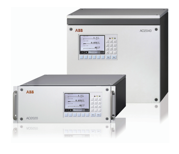
ABB AO2040-CU Ex Central Unit
ABB AO2040-CU Ex Central Unit
The specialized operating guide for ABB AO2040-CU Ex central unit (2G class) serves as a supplement to the main operating manual for the AO2000 series continuous gas analyzer (publication number 42/24-10 EN), containing key information for safe installation, start-up, and operation of the equipment. The "Analyzer Data Sheet" accompanying each device should be used in conjunction with this manual. The symbols "1, 2, 3,..." in the manual indicate safety operation points, and the symbol "●" indicates specific instructions for equipment operation.
Technical Parameter
Compliant with standards: Compliant with DMT 08 ATEX 2018 U 605 standard, explosion-proof mark Ex de IIC T4 Gb, equipment category 2G, suitable for use in Zone 1 and Zone 2 explosion hazardous areas.
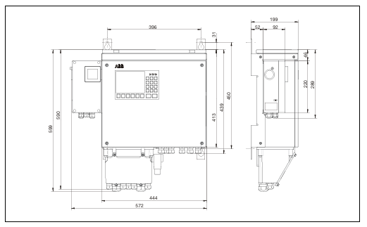
Size and weight: The equipment size is not explicitly mentioned, with a weight of approximately 28kg.
Suppress gas related parameters
Gas type: Use air that meets ISO 8573-1 standard level 3 as the suppression gas.
Gas quality requirements: maximum particle size of 40 μ m, maximum oil content of 1mg/m ³, maximum pressure dew point+3 ° C.
Working pressure range: Suppress gas working pressure to 250-500kPa (2.5-5bar).
Power supply parameters
Voltage setting: Before connecting to the power supply, it is necessary to confirm that the equipment voltage setting matches the line voltage. The specific voltage setting value is not explicitly mentioned.
Power protection device: Install suitable protection devices and easy to operate circuit breakers, specific specifications are not explicitly mentioned.
Pressure parameters
Positive pressure inside the system casing: Maintain a positive pressure of approximately 2hPa inside the system casing during operation.
Positive pressure alarm and protection threshold: When the positive pressure is below 0.8hPa or above 15hPa, disconnect the power supply and isolation relay connection circuit inside the system enclosure; When the internal pressure is below 1.2hPa, a status signal is output through passive relay contacts.
Electrical connection parameters
Potential compensation connection: External potential compensation connection or protective wire with a minimum cross-sectional area of 4mm ².
Intrinsic safety signal circuit: The total length of the intrinsic safety signal circuit for the condensate water monitor shall not exceed 75 meters, and a 100k Ω resistor shall be installed next to the sensor.
Cable connector specification: M20 threaded connector is suitable for cable outer diameters of 6-12mm.
Safety operation information
General safety requirements: The equipment must be properly handled, stored, installed, set up, operated, and maintained; Only personnel who are familiar with similar equipment and have relevant qualifications can operate it; It is necessary to comply with the content of this manual, equipment safety information, safety precautions for electrical equipment and gas operation, as well as explosion-proof regulations and standards.
Special safety instructions: Follow all explosion-proof safety measures before operation; Do not operate current carrying components in explosive risk environments except for intrinsically safe circuits; Connect the local potential compensation point first; Ensure that the equipment voltage setting matches the line voltage; Before opening the casing, disconnect all power sources and wait for 10 minutes for the power capacitor to discharge; If the equipment is damaged, unable to operate, or has poor storage and transportation conditions, it should be stopped from use.
Installation guide
Unpacking and installation: The equipment weighs approximately 28kg and requires two people to operate. The installation position should be stable; Can be installed in Zone 1 and Zone 2 explosion hazardous areas, and cannot be installed outdoors.
Suppression gas pipeline connection: Use air that complies with ISO 8573-1 Level 3 as the suppression gas; Install the accompanying compressed air conditioning filter to prevent valve damage caused by gas pipeline contamination.
Electrical connection safety precautions: Do not change the internal wiring of the factory, only modify the wiring between the isolation relay and the system controller and I/O board connectors; First, connect the external potential compensation connection or protective wire, with a minimum conductor cross-sectional area of 4mm ²; Electrical circuits need to be firmly fixed, and shielded wires need to pass through metal connectors; The intrinsic safety signal line is only connected to the blue cable connector, with a minimum distance of 8mm from other lines; the communication interface line needs to be connected through factory pre wired isolation relays; Connect the power line to the pressurized enclosure system control unit, do not directly connect it to the system enclosure port.
Electrical connection details: Clarify the application of different types of connectors (light blue M20, black M20, metal M20); The M20 threaded connector is suitable for cable outer diameters of 6-12mm. Unused connectors need to be sealed with original plugs and tightened.
Electrical equipment composition: including isolation relays, terminal blocks, line filters, pressurized enclosure system control units, isolation amplifiers, etc.
Each device has its specific functions and connection requirements.
Analysis module connection: The system bus and 24VDC cable are components of the pressurized enclosure system, with a length of not less than 1 meter; Connect the system bus cable and 24VDC cable to the central unit according to the steps.
Non intrinsic safety signal line connection: connected to the right side of the isolation relay; The intrinsic safety signal circuit of the condensate monitor is connected through a bright blue cable, with a total length not exceeding 75 meters, and a 100k Ω resistor is installed next to the sensor.
Status signal, potential compensation and power connection: The minimum cross-sectional area of the conductor for potential compensation connection is 4mm ²; Connect the status signal to control unit terminals 21 and 22; Before connecting the power supply, confirm that the voltage settings match, install appropriate protective devices and easy to operate circuit breakers, and connect control unit terminals 15, 17 and PE terminals.
Operation and maintenance
Pre start inspection: Confirm that the installation site conditions, equipment installation firmness, suppression of gas flow, shell integrity, electrical circuit connections, etc. meet the requirements.
Startup steps: Connect the power supply and suppress the gas supply. After the initial purge is completed, switch the solenoid valve to "leakage compensation" and activate the power supply of the equipment inside the system casing; After startup, the "Power", "Maintenance", and "Error" LEDs light up, and the screen displays the startup phase and software version, then switches to measurement mode.
Maintenance bypass operation: When there is no explosive environment, the bypass of the pressurized shell system control unit can be activated, which requires approval from the operations manager; Activate and deactivate the bypass according to the steps, and the bypass must be deactivated during normal operation.
Regular inspection: Conduct routine checks according to the pre startup checklist.
Appendix: Application and Design
Application and Design Overview: Used in conjunction with the AO2060 series analysis module to control and monitor the measurement and control process; The system casing is wall mounted and designed to comply with EN 60079-2 "pressurized casing with leakage compensation"; Can access intrinsic safety and non intrinsic safety signal circuits, and the system controller has no battery backup.
Pressure shell system: using air that complies with ISO 8573-1 Level 3 as the suppression gas, with a particle trap at the outlet; Perform preliminary blowdown set by the factory during startup, and maintain a positive pressure of approximately 2hPa inside the system casing during operation; When the positive pressure is lower than 0.8hPa or higher than 15hPa, disconnect the power supply and isolation relay connection circuit of the equipment inside the system casing, and after the pressure is restored, blow and activate again; When the internal pressure is below 1.2hPa, a status signal is output through passive relay contacts.
- YOKOGAWA
- Reliance
- ADVANCED
- SEW
- ProSoft
- WATLOW
- Kongsberg
- FANUC
- VSD
- DCS
- PLC
- man-machine
- Covid-19
- Energy and Gender
- Energy Access
- Renewable Integration
- Energy Subsidies
- Energy and Water
- Net zero emission
- Energy Security
- Critical Minerals
- A-B
- petroleum
- Mine scale
- Sewage treatment
- cement
- architecture
- Industrial information
- New energy
- Automobile market
- electricity
- Construction site
- HIMA
- ABB
- Rockwell
- Schneider Modicon
- Siemens
- xYCOM
- Yaskawa
- Woodward
- BOSCH Rexroth
- MOOG
- General Electric
- American NI
- Rolls-Royce
- CTI
- Honeywell
- EMERSON
- MAN
- GE
- TRICONEX
- Control Wave
- ALSTOM
- AMAT
- STUDER
- KONGSBERG
- MOTOROLA
- DANAHER MOTION
- Bentley
- Galil
- EATON
- MOLEX
- Triconex
- DEIF
- B&W
- ZYGO
- Aerotech
- DANFOSS
- KOLLMORGEN
- Beijer
- Endress+Hauser
- schneider
- Foxboro
- KB
- REXROTH
- YAMAHA
- Johnson
- Westinghouse
- WAGO
- TOSHIBA
- TEKTRONIX
- BENDER
- BMCM
- SMC
- HITACHI
- HIRSCHMANN
- XP POWER
- Baldor
- Meggitt
- SHINKAWA
- Other Brands
- UniOP
- KUKA
- IBA
- Beckhoff
- ADLINK
-
Beckhoff CX1100-0910 - Power Supply Module
-
Beckhoff C5210-0010 - Communication Module C5210
-
BECKHOFF KL1352 - Bus Terminal SET OF 2 FREE FAST SHIP
-
Beckhoff EL3058 - 8 x analog input single ended 4...20mA 85惟 shunt 12bit
-
Beckoff CX1100-0920 - UPS Module 24VDC (US SELLER) * *
-
BECKHOFF C6920-0000 - C69200000 PLC Moudule
-
Beckhoff CX5120-0115 - CPU controller module CX5120-0115
-
Unknown 15F5C1E-Y50A - Of Frequency Converters
-
Beckhoff AX5118-0000-0200 - Servo Drive HTP0
-
BECKHOFF AX5106-0000-0200 - Servo Drive
-
Beckhoff CX5240-0175 - Module (free) #U2327D YG
-
Beckhoff CP6607-0001-0000 - Compact PC Panel Economy Installation Operator 5,7 "
-
Beckhoff EP3744-0041 - 2022 EP37440041 Module
-
Beckhoff CP6209-0001-0020 - 6.5" PC Touch Screen Control Panel 24VDC
-
Beckhoff CX9020-0111 - /U900 +8x+2xEL3121+1x EL9410+3xEL1008+1x EL2008 Set
-
Beckhoff C6525-1030-0050 - Industrial PC
-
Beckoff CX1100-0920 - UPS Module 24VDC (US SELLER)
-
Beckhoff CX5010-0120 - CX5010 Processor Intel Atom Z510 B24
-
Siemens 6FC5203-0AF04-1BA1 - Operation Panel
-
Beckhoff CX5230-0175 - / 000029724 Embedded PC / Industrial PC on Rail
-
Beckhoff CP3916-0000 - industrielles Anzeige- und Bedienterminal
-
BECKHOFF CX1500-M310 - CX1000-N000 CX1000-0011 CX1000-C00L CX1100-0002 PLC Module
-
Beckhoff EL1872 - 16-channel digital input terminal
-
BECKHOFF EP2318-0001 - module
-
Beckhoff CX9020-0110 - Basic CPU Module
-
Beckhoff EL2564 - EtherCAT Terminal, 4-channel LED output, 5鈥?8VDC, 4A, RGBW
-
Beckhoff CX5130-0155 - /000105637 Automation Embedded PC
-
B&R 400 - Power Control Panel Rev D0 24 VDC
-
Beckhoff CX2020-0155 - module
-
Beckhoff CX9020-0115 - PLC Module
-
BECKHOFF EL6695 - PLC EL 6695
-
BECKHOFF EL7047 - PLC Modules
-
Beckhoff CX1000-0012 - Control HW 2.2 + CX1500-M310 + CX1000-C00L + CX1100-0002+
-
Beckhoff C6920-1039-0030 - control cabinet industrial PC CPU Celeron 1.90 GHz, 2 cores
-
BECKHOFF CX1100-0910 - PLC Module#
-
Beckhoff IL2301-B318-0000 - Coupler Box 4 Channel Digital Input |
-
Beckhoff CX7080 - Module
-
Beckhoff C6930-0060 - Industrial PC
-
Beckhoff CP7902-1060-0000 - Touchscreen 15 " CP7902
-
beckhoff CX9020-0111 - Controller module or UPS
-
Beckhoff CX8091 - PLC Module CX8091
-
Beckhoff C6640-1008-0030 - Control Cabinet Industrial PC
-
BECKHOFF CX1100-0920 - module
-
Beckhoff C9900-M921 - see pictures
-
BECKHOFF CP6829-0001-0000 - Touch Panel
-
BECKHOFF C6930-0060 - Industrial Computer
-
BECKHOFF CX8050 - PLC module
-
Beckhoff CP6202-0021-0020 - Touch Screen #
-
BECKHOFF AM3031-0C20-0000 - SERVO MOTOR
-
Unknown BCH1302N11A1C - Servo motor
-
Beckhoff EL2502 - 2-channel pulse width output terminal
-
Beckhoff EL6731 - Profibus Master / *Rev: 0025
-
Beckhoff CP3918-0010 - Control Panel
-
BECKHOFF CP2915-0010 - [24 MONTH WARRANTY] Control Panel
-
Beckhoff AX5203-0000-0202 - Servo Drive
-
Schneider TSXDSY64T2K - PLC OUTPUT MODULE
-
Beckhoff EP4174-0002 - Module-
-
Beckhoff IL2302-B318-0000 - Profibus Box
-
Beckhoff CP6709-0001-0000 - Touchpanel
-
BECKHOFF CX2030-0123 - Controller
-
Beckhoff CX9020-0111 - Processor Module
-
Beckhoff CX1020-0000 - CX Basic CPU Module
-
Beckhoff AX2003-AS - Servo Drive HTP0
-
Beckhoff C6240-1052-0040 - 4-086-06-3073 Industrial Computer CB1052-0003
-
Beckhoff EL1918 - 8 xTwinSAFE Input
-
Beckhoff AM8072-0R20-0000 - Servomotor
-
BECKHOFF AM8021-1B21-0000 - servo motor #T882 YS
-
Beckhoff EL6224 - 4 X Terminal IO-LINK
-
Beckhoff CX5140-0135 - embedded PC with Intel Atom processor 4 GB HW 3.6
-
Beckhoff CP7201-1000-0000 - Panel PC #
-
Beckhoff CX5130-0121 - Embedded-PC 4GB CPU Module HW 2.5 Industrial PC
-
Beckhoff AM8022-0D41-1002 - Servomotor
-
BECKHOFF CX2030-0130 - Module
-
BECKHOFF EL1872 - 16-channel digital input terminal
-
Unknown GXMMW.A203P33 - 1pc encoder
-
Beckhoff EL6631-0000 - EtherCAT Terminal 2-Port EL 6631
-
BECKHOFF C6925-0030 - Industrial Computer
-
Beckhoff CX8190 - A Module
-
BECKHOFF CX2040-0135 - CX2040-0135/000000927 CPU BASE MODULE i7 2715QE 2.1GHz --
-
BECKHOFF KL6023-0000 - Wireless adapter
-
Saia Burgess PCD7.F700 - PCD7F700 Communication Module
-
Beckhoff CX5130-0112 - CPU Module
-
BECKHOFF CX1020-N010 - CX1020-N000 CX1020-0111 CX1100-0004 EL2008 EL3064 EL4004
-
Beckhoff EP1819-0021 - A Module
-
Beckhoff CX2030-0120 - / 4gb with CX2100 0004
-
B&R X20-XC-0292 - Automation Powerlink Ethernet Bus Controller Module
-
Beckhoff BK3110 - One PLC Module
-
BECKHOFF KL3222 - PLC Module
-
BECKHOFF CX1500-M310 - CX1000-N000 CX1000-0011 CX1000-C00L CX1100-0002 PLC MODULE
-
Beckhoff CP3918-0010 - Control Panel
-
Beckhoff CX2030-0100-1002 - /4GB + CX2100 + CX2550 + CX2500-0060 + SSD
-
Beckhoff EP1816-0008 - PLC Module
-
Beckhoff CX5130-0112 - Module
-
Beckhoff Cx1500-m750 - CPU Hw: 1.4
-
BECKHOFF AX5112-0000-0200 - AX511200000200 Servo Driver
-
Beckhoff EL3751 - EtherCAT Terminal 1 Channel Analog Input Multifunction 24 Bit
-
Beckhoff CX1100-0002 - Power Supply Module
-
Beckhoff CP3916-1016-0010 - Control Panel
-
BECKHOFF CX9001-1101 - #NAME?
-
Beckhoff EP3174-0002 - EtherCAT Box Module
-
Beckhoff C6030-0070 - servo drive
-
Beckhoff CX2020-0120 - /4GB CPU, CX2100-0904, 3x EL6900, EL1904, 16GB Memory
-
BECKHOFF C6110 - BOX-PC 113608
-
BECKHOFF EK1914 - module #P
-
Beckhoff C6140 - Ipox IP-4GVI63 + CH7009A_DVI_TV + SIEMENS A5E00369843 + WD800AAJB
-
Beckhoff CX5020-0111 - controller Good quality
-
BECKHOFF C6015-0010 - / 6559380 ULTRA-COMPACT INDUSTRIAL PC ()
-
Beckhoff AX5203-0000-0200 - PLC module
-
Beckhoff EL2872 - 16-channel digital output terminal
-
BECKHOFF C3640-0000 - Panel Industrial PC 100/240VAC 128MB E0122L
-
Beckhoff CX8031 - Module
-
Beckhoff CX5020-0120-1002 - PLC module#
-
Beckhoff C6140 - M845B + SIEMENS A5E00369843 + C9900_A159_1 + AUTOMATA CAN PCI 1N
-
BECKHOFF AX5112-0000-0200 - Servo Drive*ie
-
B&R ECPA42-01 - Analog Output Module 4-Channel, +/- 10V Output Signal, 20mA Max
-
Beckhoff EL6631-0010 - PLC Module
-
BECKHOFF C6930-0070 - CONTROL CABINET INDUSTRIAL PC
-
BECKHOFF AX5112-0000-0200 - AX511200000200 Servo Driver
-
BECKHOFF EK9000 - Programmable Logic Controller Module EK9000 EK9000
-
BECKHOFF C6920-1028-0000 - Industrial computer
-
Beckhoff CX2030-0120 - controller Module
-
Beckhoff BX8000-0000 - Bus Terminal Controller HW 4.4
-
B&R 3NC154.60-2 - Positioning Module#
-
BECKHOFF CX1020-0122 - PLC module
-
Beckhoff AM3032-0D40-0000 - Servo Motor
-
BECKHOFF CX5020-0111 - CPU Module CX5020-0111
-
Beckhoff CB1051 - G5 Motherboard
-
BECKHOFF KL2641 - 1-channel relay output terminal

K-JIANG

Add: Jimei North Road, Jimei District, Xiamen, Fujian, China
Tell:+86-15305925923