

K-WANG


Bonfiglioli CM-232/CM-485/CM-485T Modbus Communication Manual
Bonfiglioli CM-232/CM-485/CM-485T Modbus Communication Manual
Document Fundamentals and Security
Document positioning: Belongs to the supplementary document of the frequency converter operation manual; The complete set of documents includes a quick start guide, a complete operation manual, an application manual, and module installation instructions.
safety requirements
The module disassembly and assembly must completely cut off the main power supply of the frequency converter to prevent static electricity from damaging the circuit board; Only licensed electricians are allowed to operate.
The frequency converter operates with high voltage, and there is residual voltage in the bus capacitor after power failure.
Storage conditions: The original packaging should be dry and dust-proof, and stored without electricity for no more than 1 year.
It is prohibited to plug and unplug communication modules with power on.
Module Introduction
CM‑232:RS232, Point to point 1-to-1 communication, DB9 female port X310.
CM-485: RS485, DB9 interface; CM‑485T:RS485, 7-position plug-in terminal.
The RS485 bus can accommodate up to 247 frequency converter slave stations, with a master-slave architecture where only the master station initiates messages and the slave station does not actively send them.
Factory default protocol parameters: Protocol=VABus; Baud rate 19200; Verify EVENT even verification; Slave station address=1; Watch dog 413=0 (off).
Switching Modbus requires setting parameter 395:2=Modbus RTU; 3=Modbus‑ASCII; 0=VABus original factory protocol.
Note: Slot A is the KP232 adapter (for VPlus debugging software), slot B is the CM-232/485 module. When connecting CM-232/485 to PLC, VPlus software cannot use this port and must use KP232 adapter.
Module installation and removal
Power off, remove the upper and lower cover plates of the frequency converter, and access the Slot-B communication slot.
Install the PE grounding spring (M4 screw), insert the module into Slot-B and hear a click. Secure the module to the grounding spring with the M2 screw; Knock open the prefabricated opening on the top cover for the X310 connector to pass through, and restore the cover plate.
Disassembly: Loosen the M2 screw, use a small screwdriver to open the left and right buckles of the module, alternately pull out the module, remove the PE spring, and restore the cover plate.
ESD anti-static: Do not directly touch the PCB components on the back of the module.
Pin definition, bus terminal matching, cables
1)CM‑232 DB9(X310)
Pin signal
2 RxD reception
3 TxD transmission
5 0V GND
The shell is shielded and connected to PE; the remaining pins are empty. A 1:1 direct shielded twisted pair cable is required.
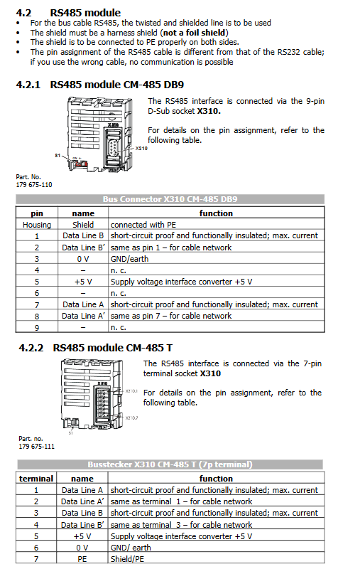
2) CM-485 DB9 version X310
Pin signal
1 B
2 B '(parallel)
3 0V
5 +5V
7 A
8 A '(parallel)
The shell is shielded and connected to PE.
3) CM-485T Terminal Edition X310
Terminal signal
1 A
2 A 'parallel connection
3 B
4 B 'parallel connection
5 +5V
6 0V
7 PE shielding ground
Bus terminal resistor S1 dip code
The first and last nodes of the bus physics must open the terminal resistor S1=ON, and all the middle nodes must be OFF.
Prohibit the simultaneous use of onboard dialing code S1 and external active terminal circuits.
RS485 recommends twisted pair shielded cables with PE connections at both ends of the shielding layer; maximum bus distance corresponding to different baud rates: 2400bps=2400m; 19200bps=1200m; 115200bps=300m。
Start configuration parameters
Parameter Number Parameter Name Description
10 Baud Rate Baud rate 2400~115200; After modification, software reset (parameter 34 written to 123) or power-off and power on are required for it to take effect
1375 Modbus Parity checksum 0=EVENT even; 1=ODD odd; 2=None without verification; The modification needs to be reset to take effect
1376 Modbus Address Slave Address 1-247; The modification takes immediate effect; 0 is the broadcast address, and there is no response to the broadcast
395 Protocol Select 0 VABus/2 RTU/3 ASCII
413 Watchdog watchdog timer 0 closed; 1-10000s; timeout report F2010 communication failure
The modification of baud rate and verification requires restarting the frequency converter; The modification of the station address takes effect immediately. Software reset method: Write parameter 34 to 123.
Detailed Explanation of Modbus Serial Protocol
5.1 master-slave model
0: Broadcast address, write command to broadcast all slave stations, no response message; 1-247 independent slave stations.
Message structure: [Slave address] [Function code] [Data] [Verify CRC/LRC].
Exception message: Function code highest position 1 (+0x80)+Exception code.
5.2 Support Function Code (including Bangfeili Custom Extension)
Function code name and purpose
0x03 reads 16 bit hold register to read 16 bit inverter parameters; Only one register can be read at a time
0x06 Write a single 16 bit hold register and write a 16 bit parameter; One register at a time
0x64 (100) Custom read 32-bit parameter read long 32-bit parameter (non-standard Modbus)
0x65 (101) Custom write 32-bit parameter write long 32-bit parameter (non-standard Modbus)
0x08 Diagnostics Diagnostics reads communication error counter, reset counter
Address encoding rule (key) Modbus request starting address 16 bits: high 4 bits=dataset number (0-9), low 12 bits=internal parameter number of the frequency converter. Example: Parameter 372, Dataset 2 → Address=0x2174. Floating point/decimal parameters: Communication transmission uses amplified integers, such as 10.3A transmitting the value 103; 100.00Hz transmission of 10000.
5.3 Exception codes
Meaning of Exception Code
1 Illegal function code
2 illegal data addresses (parameters do not exist, number of registers ≠ 1)
3 Illegal data values
4. Equipment failure at the substation; Read parameter 11 to obtain detailed low-level errors
Parameter 11 VABus SST Error Register: Read detailed errors at the bottom layer (read-only), automatically reset after reading.
5.4 RTU and ASCII transmission modes
Modbus‑RTU
Character 11 bits; A frame interval of ≥ 3.5 characters is used to determine the start and end of the frame; CRC-16 checksum (low byte first sent); Higher transmission efficiency, commonly used in engineering.
If the character gap is greater than 1.5 characters, the message will be discarded directly.
Modbus‑ASCII
Frame start character colon:, end CR+LF; LRC verification; 7-bit data; The maximum allowable interval between characters is 1 second; Low bandwidth efficiency.
5.5 Timing and Watchdog
After receiving the message, the frequency converter should wait at least 10ms before replying; The host sends the next message at least 2ms apart; if the host does not receive a response within 500ms, it will be judged as timeout. When the CPU is under high load, the timeout will be greater than 500ms.
Watchdog 413: If there is no correct Modbus message within the set time when it is not 0, report fault F2010 RS232 485 watchdog fault; 0=Turn off the watchdog.
5.6 Dataset, RAM/EEPROM read-write mechanism (emphasis)
The frequency converter has 5 sets of data sets (0-4) for multiple parameter switching.
Dataset 0-4: Write and save to EEPROM (non-volatile storage) at the same time, EEPROM has a write life of about 1 million times; Prohibit cyclic high-frequency writing as it may burn the EEPROM.
Dataset 5-9: Only writes to RAM (volatile, lost during power failure), suitable for PLC to periodically issue control words and set frequencies.
Dataset 0 → RAM Address 5
Dataset 1 → RAM Address 6
Dataset 2 → RAM Address 7
Dataset 3 → RAM Address 8
Dataset 4 → RAM Address 9
Important: Control word 410, RAM given frequency 484, RAM percentage given 524, fixed use dataset 0 (RAM), will not be written to EEPROM.
Modbus Message Instance
The document provides complete examples of RTU and ASCII:
Example of FC03 reading 16 bit parameters; Example of exception return.
FC06 Write 16 bit parameter example.
FC100 (0x64) reads 32-bit parameters.
FC101 (0x65) writes 32-bit parameters.
FC08 diagnosis: reset counter, read various communication statistics (total received messages, CRC errors, abnormal responses, overflow errors, etc.).
ACT inverter serial port control logic
Operate three core registers through Modbus:
410 Control Word control word (16 bits): Issue commands such as start stop, reset, and quick stop.
411 Status Word status word (16 bits): reads the bit status of the drive's running status, faults, warnings, reaching the given limit, etc.
484 Reference Frequency RAM: Given the RAM frequency (32-bit, -999.99~999.99Hz)
524 Reference Percentage RAM: Given percentage (32-bit, -300~300%)
The hardware enable S1IND (hardware terminal) has the highest priority, and the driver cannot be enabled solely by the bus control word. The hardware terminal must provide an enable signal.
Three control modes, selected by parameter 412 Local/Remote
Mode 0: Control via Contacts: All start and stop directions come from hardware digital inputs, and control word 410 is invalid.
Mode 1: Control via State Machine Control (DRIVECOM): Bus control word 410 implements the complete drive state machine; Standard servo/inverter bus control, supporting complete state jump, fault reset, and quick stop.
State machine: not ready → prohibit closing → ready closing → closed → enabled operation, quick stop activation, fault state.
Parameter 392 State transition5 defines the shutdown behavior when the enable switch is switched back to closed: 0 free sliding; 1. DC braking; 2 Slope shutdown.
Mode 2: Control via Remote Contacts Remote Virtual Terminal: Control word 410 simulates hardware DI input for each bit; Equivalent to mapping all digital inputs such as S1IND-S6IND to control word bits.
Given source mode (parameter 434 Ramp Setpoint ramp setting source)
1=Only internally given; 2=Given only bus RAM; 3=Internal given+bus given superposition. Readable actual value parameters: 228 internal reference, 282 bus reference, 283 ramp output reference frequency.
ACU (ACTION Cube) Control
ACU is a compact servo drive for Cube, also using 410 control words/411 status words/484/524 given. Differences:
The hardware safety enable is a dual channel STO safety terminal for STOA/STOB (S1IND/S7IND), which must be hardware effective, and the bus cannot replace hardware safety.
ACU supports external 24V control power supply; Modbus communication can still be maintained even when the main power is disconnected, and the status word bit4 (Voltage enabled) provides feedback on whether the main power supply is powered on.
The meaning of some bits in the state machine of the motion control mode (configuration 30=x40) has changed.
Key Parameter Index
The manual lists the communication related VAL actual value menu and PARA parameter menu; Key Points:
249 Active Data Set: The current active dataset;
Read the status of the DI terminal using 250 digital inputs;
260 Current Error Current fault code;
270 Warning bit encoded warning word;
414 Data Set Selection bus switching dataset;
637/638: Fast stop shutdown threshold and holding time;
632 DC braking time.
Appendix: Alarm and Fault Codes
Warning (270): 16 bit encoding, overheating, Ixt overload, motor temperature, phase fault, V-band monitoring, etc.
Fault error code (260): F01 overload, F02 radiator overheating, F03 internal temperature, F04 motor temperature, F05 output short circuit, F07 bus voltage, F20 10: RS232 485 communication watchdog fault.
Attached ASCII code table 0x00-0x7F.
- YOKOGAWA
- Reliance
- ADVANCED
- SEW
- ProSoft
- WATLOW
- Kongsberg
- FANUC
- VSD
- DCS
- PLC
- man-machine
- Covid-19
- Energy and Gender
- Energy Access
- Renewable Integration
- Energy Subsidies
- Energy and Water
- Net zero emission
- Energy Security
- Critical Minerals
- A-B
- petroleum
- Mine scale
- Sewage treatment
- cement
- architecture
- Industrial information
- New energy
- Automobile market
- electricity
- Construction site
- HIMA
- ABB
- Rockwell
- Schneider Modicon
- Siemens
- xYCOM
- Yaskawa
- Woodward
- BOSCH Rexroth
- MOOG
- General Electric
- American NI
- Rolls-Royce
- CTI
- Honeywell
- EMERSON
- MAN
- GE
- TRICONEX
- Control Wave
- ALSTOM
- AMAT
- STUDER
- KONGSBERG
- MOTOROLA
- DANAHER MOTION
- Bentley
- Galil
- EATON
- MOLEX
- Triconex
- DEIF
- B&W
- ZYGO
- Aerotech
- DANFOSS
- KOLLMORGEN
- Beijer
- Endress+Hauser
- schneider
- Foxboro
- KB
- REXROTH
- YAMAHA
- Johnson
- Westinghouse
- WAGO
- TOSHIBA
- TEKTRONIX
- BENDER
- BMCM
- SMC
- HITACHI
- HIRSCHMANN
- XP POWER
- Baldor
- Meggitt
- SHINKAWA
- Other Brands
- UniOP
- KUKA
- IBA
- Beckhoff
- ADLINK
-
FANUC A06B-0169-B088 - AC Servo Motor Alpha M40 3000 3 KW
-
ALPHA WIRE 1299C-SLATE-1000 - Multi-Conductor Cable Wire
-
alpha / Wittenstein SK+180S-MF1-10-1M1-1K - Hypoid Gearbox i=10
-
ALPHA WIRE 1181/40C SL005 - Multi-Conductor Cable Wire
-
Generic / DSI Straight Anatomic Plastic Adapter Head + Screw Hex - Dental Implant Fixture
-
Alpha II-650 MV6500526A - Power Supply Unit
-
ALPHA WIRE 7036 WH001 - Hook-Up Wire
-
FANUC RDCGM00000004O / TP 050-MF1-7-061-000 - Gear Reducer / Alpha Gearbox
-
Alpha II-650 MV6500436A - TDK-Lambda Power Supply Unit
-
Alpha S-Alpha600 J60033 - 600W Switching Power Supply Unit
-
Alpha 1500W J00032 - Power Supply Unit
-
Alpha 600W H60638 - Switching Power Supply Unit
-
Alpha 650 MV6500314A - Power Supply Unit
-
Aloka UST-5413 - Linear Probe for Prosound Alpha 6
-
ALPHA WIRE TFT25015 NA002 - High Temperature Heat Shrink Tubing Wire Sleeving
-
JAVAD ALPHA2 / GrAnt-G3 - GPS Receiver
-
Alpha 400W H47318 - Switching Power Supply Unit
-
Alpha SG-ALPHA-202-001 / Q1001-010-001 - Circuit Board Module
-
Antlia Dual ERF H-Alpha & Cak/CaH - Density Astronomical Accessory
-
ALPHA WIRE 5100C SL033 - Multi-Conductor Cable Wire
-
ALPHA WIRE 5098C-SL033 - Multi-Conductor Cable Wire
-
Fanuc A06B-6290-H105 - Alpha Sv 80hv-B Module Servo Amplifier
-
FANUC A06B-6240-H105 - Aux Axis Alpha aiSV 80 Servo Amplifier
-
Endress+Hauser Alpha-Log RSA10-61B1S / 42974737/0130 - Data Logger Measurement Instrument
-
ALPHA WIRE 6363-SL002 - Multi-Conductor Cable Wire
-
Alpha SP100S-MF1-7-1K1-2S - Gear Reducer
-
Alpha SP 100G-MF1-4-0H1-2S-PGG - Planetary Gear Reducer
-
FANUC A06B-0143-B175 #0275 - Alpha 12/3000 AC Servo Motor
-
James Burn Alpha Doc P33 / GBC PDI - Automatic Punch DocuPunch
-
Titus HVAC 105383-01 - ALPHA BAC Controller and Actuator
-
Wittenstein Alpha SP 100S-MF2-20-0E0-2S - Planetary Gearbox i=20
-
Kashiyama Alpha-85-ZV / SP-8026G - Pump Controller
-
Christ Alpha 2-4 LDplus - Freeze Drier Part N/ 101542
-
Lambda / Alpha H40896 - 400W Power Supply Unit
-
Wittenstein Alpha LP-070S-MF1-3-1E1-38 - Planetary Gearbox
-
Matrox / EXO-2480 133-D06-3 / 398-17962-1 - Alpha Numeric PCB Board
-
Fanuc A06B-6096-H204 - Dual Axis Alpha Servo Amplifier Module
-
Alpha Wire 5002C-SL001 - Multi-Conductor Cable 2 Conductors 22AWG 300VAC
-
Alpha 600W H60638 - Switching Power Supply Unit
-
Alpha Scientific Spin Precession Dual Electro Magnet Beam Line Chamber - Electro Magnet Beam Line Chamber
-
ALPHA WIRE 6017C SL005 - Multi-Conductor Cable Wire
-
ALPHA WIRE 65804 SL002 - Multi-Conductor Cable Wire
-
Fanuc A06B-0152-B010 - AC Servo Motor Alpha A30/2000 with Brake
-
ALPHA WIRE 5856-VI001 - Hook-Up Wire
-
ALPHA WIRE M13142-SL001 - Multi-Conductor Cable Wire
-
Alpha & Omega AOZ1017 - 8-Pin SOIC SMD Buck Switching Regulator IC
-
Alpha 600W H67027 CA600 - 600W Switching Power Supply Unit
-
ALPHA WIRE 2845/7-RD001 - Hook-Up Wire
-
Wittenstein Alpha VH+063S-MF1-10-6H1-1K-0C2 - Worm Gear Reducer i=10
-
ALPHA WIRE 2414C SL022 - Multi-Conductor Cable Wire
-
ALPHA WIRE 5672-SL005 - Multi-Conductor Cable Wire
-
BECKHOFF / Alpha AM8021-0B10-0000 + CP 040-MO1-10 - Servo Motor with Planetary Gearbox
-
ALPHA Systems Lab Inc MBA-WV1-F / PCB-WV1-F - PCB Board
-
FANUC A06B-0826-B201 - Alpha P12 AC Spindle Motor
-
WF & HC / Alpha-E 10045 - Tiller Bar Flat Flange Inlet 3150LB 3X 2.5 Inch
-
Seiler Alpha Air 3 - Dental Microscope
-
Alpha 400W H47223 - Switching Power Supply Unit
-
Wittenstein Alpha SP 180S-MC1-5-1M0-2K - Planetary Gearbox
-
FANUC A06B-6117-H211 - Servo Amplifier Module Alpha iSV 160/160 Amp
-
Alpha S-Alpha600 J60033 - 600W Switching Power Supply Unit
-
Adaptive Alpha Eclipse StreetSmart Model 17X - Master Slave LED Sign 44 x 44 Inch
-
ALPHA WIRE 391697-WH005 / 391697WH005 - Hook-Up Wire
-
Generic 22W Laser Engraver Cutter - Smart Air Pump APP Control CNC Dual-core CPU DIY Tools
-
FANUC A06B-6102-H226 / A06B6102H226 - Spindle Amplifier Module
-
FANUC A06B-6090-H006 / A06B6090H006 - Servo Power Supply Module
-
Alpha Wire Apr-19 - High Low Temperature Cable 75 FT
-
Wittenstein Alpha HG+ 075S-MF2-28-6E1-1S10 - Hypoid Gearbox Reducer i=28
-
Alpha J00032 - 1500W Power Supply Unit
-
Alpha H47038 - 400W Power Supply Unit
-
FANUC A06B-6096-H204 - Dual Axis Alpha Servo Amplifier Module
-
Wittenstein Alpha LPB090-MO1-10-111-00 - Alpha Planetary Gearbox
-
ALPHA WIRE 2842/19-YL001 - Hook-Up Wire
-
WITTENSTEIN ALPHA HG+060S-MF1-56C1-1K00 - Planetary Gearbox
-
Basler A102K Alpha VIS - Black and White CCD Industrial Camera
-
Alpha H40935 - 400W Power Supply Unit
-
FANUC A06B-6114-H207 - 2-Axis Servo Amplifier Module SVM20/40i Alpha i Series
-
TDK-Lambda / Alpha H47318 - 400W Switching Power Supply Unit
-
HITACHI Aloka Prosound Alpha 7 Premier - Diagnostic Ultrasound System
-
Alpha SP100S-MF1-4-1E1-2S - Precision Gear Reducer
-
FANUC A20B-2001-0950 - Control Circuit Board PCB
-
ALPHA WIRE 2855/1-GR001 - Hook-Up Wire
-
FANUC A06B-6096-H204 - Dual Axis Alpha Servo Amplifier Module
-
Wittenstein Alpha LPB090-MO1-10-111-00 - Alpha Planetary Gearbox
-
ALPHA WIRE 2842/19-YL001 - Hook-Up Wire
-
Basler A102K Alpha VIS - Black and White CCD Industrial Camera
-
Wittenstein Alpha LP 090-M01-7-111-000 / Schneider - Gear Box i:7 Schneider Electric Servo Motor
-
LAMBDA ALPHA 600W H60554 - Switching Power Supply Unit
-
Fanuc A06B-0238-B100 / A860-2000-T301 - AC Servo Motor with Encoder
-
FANUC A06B-6290-H322 - ALPHA iSV 10/10/10HV-B 3-Axis Servo Drive
-
Polymotor Italiana 9919 121 90332 / Alpha SP75-M1-3 - D.C. Permanent Magnet Motor with Gearbox
-
MJ Research PTC-200 - PCR DNA Engine Thermal Cycler with Dual 48-Well Alpha Block
-
ALPHA WIRE 5002C-SL002 - Multi-Conductor Cable Wire
-
Fluke / Victoreen ASM 990 / 489-110D - Biomedical Radiation Detector Probe with Pelican Case
-
ALPHA WIRE 5855-BK001 - Hook-Up Wire 22AWG Silver Plated Copper
-
Tetra / Alpha 600W H60552 - Switching Power Supply Unit
-
Bruker Alpha FTIR Spectrometer / Alpha-P ATR - Infrared Spectrometer FTIR Instrument
-
Simagic AlphaM-FX-C 290mm FX-C - Formula Steering Wheel with Alpha Mini Wheel Base
-
Alpha Wire 5152C 20/2C - XtraGuard High Performance Instrumentation/Control Cable
-
ALPHA WIRE 1219/40C SL005 - Multi-Conductor Cable Wire
-
ALPHA WIRE 3131441 TN005 - Multi-Conductor Cable Wire
-
ALPHA WIRE 2172-SV005 - Multi-Conductor Cable Wire
-
FANUC A20B-2100-0742 - ALPHA ia Servo Control Board
-
Olympus Endo Alpha Cart TI-A1 - Medical Equipment Cart with Accessories
-
ALPHA WIRE 74010-BK002 - Multi-Conductor Cable Wire
-
Fanuc A06B-6110-H026#N - ALPHA i Power Supply Module PSM-26i
-
Alpha Laval SX2/013 - Rotary Lobe Pump
-
Alpha II-450P MV4500007B - Switching Power Supply Unit
-
TDK-Lambda / Alpha 400W - Switching Power Supply Unit
-
ALPHA ALPHA6000E-3015GB/3018PB - Frequency Inverter Drive Power Converter
-
ALPHA WIRE 391245-WH005 - Hook-Up Wire
-
Alpha H60562 CA600 - 600W Switching Power Supply Unit
-
Fanuc A06B-0147-B675 - Alpha 22/2000 3.8kW 2000rpm AC Servo Motor
-
ALPHA WIRE 9821 - Twinaxial Cable 1PR 25AWG Poly Insulation
-
Fanuc / Alpha A16B-2203-0820 - ALPHA i Spindle Wiring PCB
-
FANUC A20B-2100-0742 - ALPHA ia Servo Control Board
-
Fanuc A06B-6096-H104 - Alpha Servo Module
-
Fuji Electric RYT202D5-VV2 / Faldic Alpha5 - Servo Amplifier
-
ALPHA WIRE 2817/6 20 AWG - PTFE High Temperature Cable
-
Aloka Prosound Alpha 10 / EU-6031C / JB-274D - High Voltage Power Supply for Ultrasound
-
Wittenstein Alpha SP 140S-MF1-5-01F-2S - Planetary Gearbox
-
FANUC A06B-6124-H205 - Alpha iSV Servo Amplifier Module
-
TDK-Lambda / Alpha MV6500314A - 650W Power Supply Unit
-
TDK-Lambda / Alpha H47318 - 400W Switching Power Supply Unit
-
Alpha H47318 - 400W Switching Power Supply Unit
-
CNC Bearing / Alpha AR090-S1-300-20-N - Robotics Bearing Component
-
Alpha CA400 5A,3.3Q,5B,12/12E / DXH47037 - 400W Power Supply Unit
-
FANUC A20B-2100-0742 - ALPHA ia Servo Control Board
-
Fanuc / Amada A04B-0810-C403 / LC1212 alpha II - Pressure Regulator

K-JIANG

Add: Jimei North Road, Jimei District, Xiamen, Fujian, China
Tell:+86-15305925923