
K-WANG


Rockwell Automation ControlLogix 5570 and 5560 controllers
Features ControlLogix 5570 ControlLogix 5560
Power Supply and Memory Backup Energy Storage Module (ESM) Lithium Battery (1756-BA1/BA2/BATM)
Built in communication port USB 2.0 (temporary programming only, cable length ≤ 3m, no hub) RS-232 serial port
The maximum number of connections is 500 and 250
Non volatile storage SD card (standard 1784-SD1 1GB) CompactFlash card (available separately)
Status display: 4-line scrolling text screen+4 indicator lights, 6 indicator lights (no text screen)
Representative models 1756-L71/L72/L73/L74/L75 1756-L61/L62/L63/L64/L65
Rockwell Automation ControlLogix 5570 and 5560 controllers
Product Overview and Classification
1. Controller types and core differences
The ControlLogix series controllers are divided into two major series, 5570 and 5560, as well as extreme environment type (- XT suffix) and Armor protection type (- EROM suffix). The core differences are as follows:
Features ControlLogix 5570 ControlLogix 5560
Power Supply and Memory Backup Energy Storage Module (ESM) Lithium Battery (1756-BA1/BA2/BATM)
Built in communication port USB 2.0 (temporary programming only, cable length ≤ 3m, no hub) RS-232 serial port
The maximum number of connections is 500 and 250
Non volatile storage SD card (standard 1784-SD1 1GB) CompactFlash card (available separately)
Status display: 4-line scrolling text screen+4 indicator lights, 6 indicator lights (no text screen)
Representative models 1756-L71/L72/L73/L74/L75 1756-L61/L62/L63/L64/L65
2. Special Model Description
Extreme environment type (- XT): such as 1756-L73XT/L63XT, supports working temperatures of -25~+70 ° C, and other functions are consistent with the corresponding basic model.
Armor protective type (- ROM): such as 1756-L72EROM/L73EROM, integrated with 1756-L7x controller and 2 EtherNet/IP DLR communication modules, IP67 protection level, suitable for machine installation, ESM non removable.
Installation and hardware configuration
1. Installation environment requirements
Environmental conditions: Pollution level 2 industrial environment, overvoltage category II, altitude ≤ 2000m, no derating requirements; Storage temperature -40~+80 ° C, working temperature for conventional type 0~+60 ° C, extreme type -25~+70 ° C.
Shell requirements: It needs to be installed in a shell that complies with NEMA 250 or IEC 60529 standards, with a flame retardant rating of 5VA (non-metallic shells need to be certified), and can only be opened with tools inside. The explosion-proof environment needs to additionally comply with ATEX/IECEx requirements (such as Zone 2 environment requiring an IP54 or above shell).
2. Core hardware installation steps
(1) Key installation of ControlLogix 5570
**Chassis and power supply pre installation * *: Chassis and power supply need to be installed according to the manuals "1756-IN621 (Chassis)" and "1756-IN619 (Power Supply)" first.
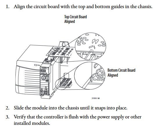
Controller insertion: Align the upper and lower rails of the chassis, slide in to the buckle lock, and ensure that it is flush with adjacent modules; Attention should be paid to the risk of electric arc in explosion-proof environment during live plugging and unplugging. It is recommended to perform power-off operation.
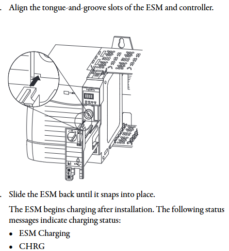
ESM installation: Align with the tongue and grain slot and push it into the buckle for fixation. After installation, start charging (up to 2 minutes, the status screen displays "CHRG"). Do not turn off the power before charging is complete, otherwise the program may be lost.
SD card operation: Open the SD card card, insert the 1784-SD1/SD2 card (recommended original card to avoid data damage), and press it until the card buckle locks; Before removal, it is necessary to confirm that the SD indicator light is off and that the explosion-proof environment requires power-off operation.
(2) Key installation of ControlLogix 5560
Battery installation: Series A uses 1756-BA1/BATM, Series B uses 1756-BA2, connect the positive and negative poles (red+black -), write the replacement date and paste it on the inside of the cabinet door.
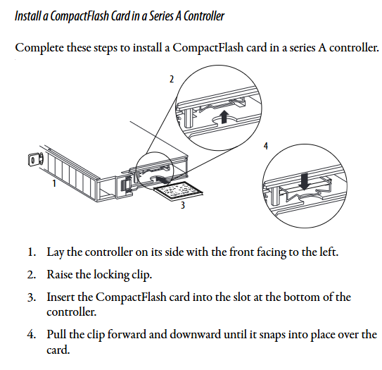
CompactFlash card operation: Series A needs to lift the locking clip to insert, Series B needs to push open the buckle and insert, and before removing, confirm that the OK indicator light is green.
3. Hardware security specifications
Static protection: Before operation, touch grounded objects to discharge electricity, wear a grounding wristband, avoid touching connector pins and internal circuits, and use anti-static workstation storage devices.
Explosion proof requirements: In Class I Zone 2 (Groups A-D) environments, equipment/components can only be plugged in and out after power failure or confirmation of non hazardous areas; It is prohibited to replace non certified components, and batteries must be replaced in non hazardous areas.
Software configuration and firmware upgrade
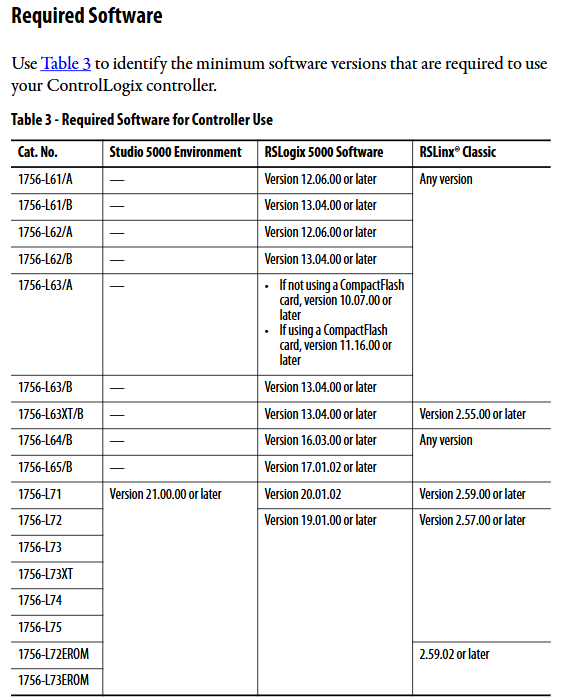
1. Essential software and version requirements
Different controller models need to be matched with specific software versions, and the core requirements are as follows:
Controller model Studio 5000 environment minimum version RSLogix 5000 minimum version RSLinx Classic minimum version
1756-L71/L72/L73 and other V21.00.00 V20.01.02 V2.59.00
1756-L61/A - V12.06.00 any version
1756-L63XT/B - V13.04.00 V2.55.00
2. Firmware upgrade method
Supports two methods: ControlFLASH software and AutoFlash (built-in in Logix Designer). The steps are as follows:
(1) ControlFLASH upgrade
Connect the controller (USB/Ethernet), start ControlFLASH, select the controller model and network driver.
Select the target firmware version (download the matching version from the official website to avoid file corruption), click "Finish" to start the upgrade, and do not turn off the power during the process.
After the upgrade is completed, the controller automatically restarts and the confirmation status screen displays the new firmware version (such as "Rev 30.011").
(2) AutoFlash upgrade
Create a project in Logix Designer, click on "Who Active" to find the target controller, and select "Update Firmware".
Select the firmware file path and version, confirm that the controller is in "Remote Program" mode and there are no uncleared faults, and click "Update".
During the upgrade process, the progress is displayed (5570 points for "update count/block count", 5560 only displays "block count"), and the firmware version is verified after completion.
3. Memory and storage configuration
5570 series: SD cards are used to store project and fault logs, supporting three modes: "power on load", "load when memory is damaged", and "user triggered load". Locking the SD card can prevent firmware from being overwritten.
5560 series: The CompactFlash card needs to be configured with the "store/load" parameter in Logix Designer, supporting program backup and recovery. When replacing the battery, ensure that there is a backup in the card to prevent data loss.
Communication network configuration
1. Supported communication protocols and modules
The controller supports multiple types of industrial networks and requires corresponding communication modules. The core configuration is as follows:
Network type, communication module model, core function, maximum number of connections/bandwidth limit
EtherNet/IP 1756-ENBT/EN2TR/EN3TR supports production and consumption tags, I/O control, and HMI communication. 1756-EN3TR supports 256 movements in 128 axes (EN2T/EN2TR); 128 (ENBT)
ControlNet 1756-CNB/CN2/CN2R/CN2RXT deterministic real-time communication, supporting 64 redundant media (CN2R/CN2RXT) (CNB/CNBR); 128 (CN2/CN2R)
DeviceNet 1756-DNB connects distributed I/O and drivers, supports scanning list configuration with 124 DINT input/123 DINT output
Data Highway Plus (DH+) 1756-DHRIO/DHRIOXT connects PLC-5/SLC controllers, supporting 32 sites at 57.6/115.2/230.4 kbps rates
HART 1756-IF8H/OF8H analog I/O+digital signal superposition, supports direct connection to HART transmitter for device diagnosis
2. Key steps for communication configuration
(1) EtherNet/IP configuration
Add modules such as 1756-EN2T in the "I/O Configuration" of Logix Designer and set the IP address (supporting BOOTP/DHCP allocation).
Configure "Production/Consumption Tags": Production tags need to specify the number of consumers, while consumption tags need to match the production tag data type and RPI (Request Packet Interval).
Remote I/O configuration: Reduce the number of connections through "rack optimization connections", and a single connection can cover the entire remote rack I/O.
(2) Serial Communication (5560 Series)
Connect the 1756-CP3 serial port cable, configure the "RS-232 DF1 device driver" in RSLinx, and select the "Logix 5550/CompactLogix" device type.
Supporting protocols: DF1 master-slave/point-to-point/wireless modem, DH-485, ASCII, Modbus (requiring MSG instruction programming), ASCII protocol requires configuring buffer size (1-4096 bytes) and termination characters.
Programming and Application Development
1. Control program structure
The Logix 5000 control program consists of a three-level structure of "task program routine", with the following core rules:
Tasks (up to 32):
Continuous task (1): lowest priority, utilizing idle CPU time for cyclic execution.
Periodic task: Execute at set intervals (0.1~2000000ms), priority 1~15 (highest 1).
Event task: triggered by triggering conditions (such as I/O status changes, consumption tag triggers) for execution.
Program (up to 1000 per task, V24+): Contains local tags, parameters, main routines, fault routines, supports "scheduled execution" (executed in sequence) and "unplanned execution" (only verified and not running).
Routine: executable code written in a single programming language, supporting ladder diagrams (LD), function block diagrams (FBD), structured text (ST), and sequential function diagrams (SFC).
2. Core programming functions
(1) Production/Consumption Tags (Interlock Data)
Production label: One controller releases data, and multiple controllers (up to 32) consume it simultaneously. It must be on the same network (not bridged across networks), and the data type and array dimension must be consistent.
Connection calculation: The production label occupies "number of consumers+1" controller connection, the consumption label occupies 1 connection, and the communication module occupies an additional 1 connection.
(2) MSG instruction (message communication)
Supports types such as "CIP Data Table Read/Write", "PLC-5/SLC Communication", "General CIP", etc. It can cache connections (optimize speed during repeated execution, up to 32 cache connections) or non cache connections (release connections after execution).
Block Transfer requires the configuration of a "request/response" data area, which is suitable for high-speed counters, frequency converters, and other devices.
(3) Motion control
Supports EtherNet/IP integrated motion (Kinetix 350/5500/6500 drivers), Sercos interface (1756-M03SE/M08SE module), and analog interface (1756-HYD02 module).
Core instructions: MSO (servo enable), MAH (axis return to zero), MAJ (axis jog), MAM (axis positioning), need to create "axis labels" and configure parameters such as speed and acceleration.
3. PhaseManager tool (device phase control)
Function: Divide device operation stages (such as Resetting/Running/Holding) according to the S88/Pack ML state model, simplify process programming, support "action state" (executing operations) and "waiting state" (waiting when conditions are met).
Core instructions: PSC (Stage Completion Signal), PCMD (Stage State Switching), PFL (Stage Fault Signal), which need to be enabled in Logix Designer V21+and support multitasking scheduling.
- YOKOGAWA
- Reliance
- ADVANCED
- SEW
- ProSoft
- WATLOW
- Kongsberg
- FANUC
- VSD
- DCS
- PLC
- man-machine
- Covid-19
- Energy and Gender
- Energy Access
- Renewable Integration
- Energy Subsidies
- Energy and Water
- Net zero emission
- Energy Security
- Critical Minerals
- A-B
- petroleum
- Mine scale
- Sewage treatment
- cement
- architecture
- Industrial information
- New energy
- Automobile market
- electricity
- Construction site
- HIMA
- ABB
- Rockwell
- Schneider Modicon
- Siemens
- xYCOM
- Yaskawa
- Woodward
- BOSCH Rexroth
- MOOG
- General Electric
- American NI
- Rolls-Royce
- CTI
- Honeywell
- EMERSON
- MAN
- GE
- TRICONEX
- Control Wave
- ALSTOM
- AMAT
- STUDER
- KONGSBERG
- MOTOROLA
- DANAHER MOTION
- Bentley
- Galil
- EATON
- MOLEX
- Triconex
- DEIF
- B&W
- ZYGO
- Aerotech
- DANFOSS
- KOLLMORGEN
- Beijer
- Endress+Hauser
- schneider
- Foxboro
- KB
- REXROTH
- YAMAHA
- Johnson
- Westinghouse
- WAGO
- TOSHIBA
- TEKTRONIX
- BENDER
- BMCM
- SMC
- HITACHI
- HIRSCHMANN
- XP POWER
- Baldor
- Meggitt
- SHINKAWA
- Other Brands
- UniOP
- KUKA
- IBA
- Beckhoff
- ADLINK
-
Beckhoff EP9224-0037 - 4-Channel Power Distribution Box EtherCAT
-
Beckhoff CX2900-0026 - Solid State Flash Memory Card 20GB CFast
-
Beckhoff BK7500 - SERCOS Interface Fieldbus Bus Coupler Terminal
-
Beckhoff Ep2328-0002 - 4-Channel Input 4-Channel Output EtherCAT Box IP67
-
Beckhoff CX1020-0111 - Controller Kit Combo Interface Modules
-
B&R X20AI2237 - X20 System Analog Input Interface Module
-
Beckhoff CP2221-0010 - Multi-Touch Built-In Panel PC Touchscreen
-
Beckhoff CX1500-M310 - Fieldbus Master Interface Module 24V
-
Beckhoff CX2100-0904 - Power Charging Module Smart UPS Extension
-
Beckhoff CP3918-0000 - Multi-Touch Control Panel 18.5-Inch Monitor
-
Beckhoff CP2915-0000 - 15-Inch Multi-Touch Built-In Control Panel
-
Beckhoff CP7037-1027 - HMI Industrial Control Panel Built-In PC
-
Beckhoff EL3152 - 2-Channel Analog Input Terminal 4-20mA EtherCAT
-
Beckhoff CP6607-0000-0020 - 5.7-Inch Built-In Panel PC HMI Touch
-
Beckhoff EJ1809-0000 - 16-Channel Digital Input Pluggable Signal Level Terminal
-
Beckhoff AM8563-0N10-0000 - Synchronous Servo Motor
-
Beckhoff AX2006-S60600-520 - Compact Servo Drive Inverter
-
Beckhoff AM8053-0K20-0000 - Servo Motor with Planetary Gearbox AG3210
-
Beckhoff AM8042-0FH1-0000 - Synchronous Servo Motor
-
Rexroth R911338600 - IndraControl V HMI Terminal Beckhoff PCI Card FC9002
-
Beckhoff AX5125-0000 - 3 Phase Industrial Servo Drive 1000Hz
-
Beckhoff EP2328-0002 - 4-Channel Digital Input 4-Channel Output EtherCAT Box
-
B&R 7CP476-02 - System 2005 RTD CPU Module 3IF681.86 Interface
-
Beckhoff AX8620-0000-0000 - Power Supply Module Axis Drive System
-
Beckhoff CX1010-0111 - PLC Module CPU Controller 24V
-
Beckhoff AM8043-0H10-0000 - Synchronous Servo Motor
-
Beckhoff C6240-1009 - Control Cabinet Industrial PC Mainframe
-
Beckhoff BX8000-0000 - Bus Terminal Controller HW 4.4 Standalone
-
Beckhoff CP7721-1089-0020 - 12.1-Inch Touch Screen HMI Panel PC
-
Beckhoff CP7132-0001 - Industrial Built-In Panel PC Screen
-
Beckhoff CP2912-0010 - Multi-Touch Built-In Control Panel Display
-
Beckhoff CP2915-0000 - 15-Inch Multi-Touch Built-In Control Panel
-
Beckhoff AM8532-1EN0-0000 - Synchronous Servo Motor
-
Beckhoff AX5203-0000 - 2-Channel Digital Compact Servo Drive
-
Beckhoff CX2020-0141 - Embedded PC Core CPU Module
-
Beckhoff CP6832-0002-0010 - Built-In Industrial Control Panel Display
-
Beckhoff CX5020-0112 - Embedded PC CPU Control Module
-
Beckhoff CX5140-0175 - 4GB Embedded PC CPU Unit 24V
-
Beckhoff EL3681-0030 - Digital Multimeter Calibration Terminal EtherCAT
-
Beckhoff CP7201-1000-0000 - Industrial PC Touch Screen HMI Monitor
-
Beckhoff CP7232-1001-0000 - Industrial Panel PC Touch Screen
-
Beckhoff C6930-1032-0040 - Control Cabinet Industrial PC System
-
Beckhoff AX5125-0000 - 3 Phase Industrial Servo Drive 1000Hz
-
Beckhoff CP3916-1424-0000 - Multi-Touch Built-In Control Panel
-
B&R 1900071142 - Lemoine Fieldbus Communication Interface Module
-
Beckhoff EL2872 - 16-Channel Ribbon Cable Digital Output Terminal
-
Beckhoff CX2030-0120 - Embedded PC CPU Base Module Controller
-
Beckhoff CP3919-0000 - 19-Inch Multi-Touch Control Panel Touchscreen
-
Beckhoff AX5101-0000-0202 - Servo Driver Compact Intelligent Drive 180V
-
Beckhoff CX5130-0135 - Embedded PC Controller Module
-
Beckhoff CP3719-1061-0010 - Multi-Touch Panel PC Outer Housing Enclosure
-
Beckhoff CP3919-1033-0000 - 19-Inch Touch Industrial Panel Keyboard
-
Beckhoff CX5020-0111 - Embedded PC PLC CPU Module
-
Beckhoff FC5102-0000 - 2-Channel CANopen PCI Control Board Card
-
Beckhoff CX9001-1101 - Embedded PC CPU Network I/O System Module
-
Beckhoff CX1100-0920 - Smart Position Sensor Interface Module
-
B&R 4P3040.01-490 - Operator Panel PLC Interface Communication Module
-
Beckhoff CP2612-0000 - Dual-Touch Built-In Panel PC HMI
-
Beckhoff CP7002-1043-0010 - Touchscreen Display HMI Panel Terminal
-
Beckhoff CX9020-0115 - Embedded PC Controller Module
-
Beckhoff CX5140-0155 - 4GB Embedded PC CPU Module Die Industry
-
B&R 7DI435.7 - System 2005 Universal Digital Input Output Module
-
Bihl+Wiedemann BWU1568 - AS-i Master to Profibus Gateway Module
-
Beckhoff C6920-0070 - Control Cabinet Industrial PC 8GB Win 10
-
B&R X20AI2322 - 2-Channel Temperature Analog Input Module
-
Beckhoff CP2912-0000 - 12-Inch Touchscreen Display Monitor Screen
-
Beckhoff CP6022-1001-0010 - 15-Inch Built-In Control Panel
-
Beckhoff AM8031-0D10-0000 - Synchronous Servo Motor
-
Beckhoff CX5010-0111 - Embedded PC Controller CPU Module
-
Beckhoff CP7232-1000-0000 - Industrial Panel PC Touch Display Screen
-
Beckhoff CP7802-0011-0000 - 15-Inch Industrial Touchscreen Control Panel
-
Beckhoff C6320 - Control Cabinet Industrial PC
-
Beckhoff CX1030-0012 - Basic CPU Module Windows CE 6.0
-
Beckhoff CP2919-0000 - Installation Multi-Touch Control Panel
-
Beckhoff CX1020-0000 - Controller Set Stack System Pack
-
B&R 3DO480.6 - System 2005 Digital Output Module
-
Beckhoff EL3101 - 1-Channel Analog Input Terminal Differential +/-10V
-
Beckhoff AX8108-0200-0000 - Axis Feed Module Servo Drive
-
Beckhoff CP7802-1241-0010 - 15-Inch Industrial Touchscreen Control Panel
-
Beckhoff FC2002-0000 - 2-Channel Lightbus Data Acquisition PCI Card
-
Beckhoff CX5120-0155 - 2GB Embedded PC Intel Atom Controller
-
Beckhoff Cx9020-0111 - 1GB Basic CPU Module Embedded PC
-
Beckhoff CP6901-0001-0000 - 12-Inch Economy Built-In Control Panel
-
Beckhoff CX9020-0111 - Embedded PC CPU Basic Module
-
Beckhoff CX5130-0100 - 4GB Embedded PC CPU Module
-
Beckhoff CP2715-0010 - Multi-Touch Built-In Panel PC
-
Beckhoff CX2033-0175 - Embedded PC CPU Module Core i7
-
Beckhoff CP7201-1000-0000 - 12-Inch Touchscreen Panel PC AMAT Green Box
-
Beckhoff EL4038 - 8-Channel Analog Output Terminal 0-10V EtherCAT
-
Beckhoff CP6802-0000-0000 - Built-In Control Panel HMI Screen
-
Beckhoff CP6500-1012-0060 - Control Cabinet PC Interface Unit
-
Beckhoff FC5202-0000 - 2-Channel DeviceNet Master PCI Interface Card
-
Beckhoff CP6606-0001-0020 - 7-Inch Economy Panel PC Touch
-
Beckhoff CP2921-0010 - Multi-Touch Integrated Control Panel Display
-
Beckhoff CP7802-0001-0010 - 15-Inch Touch Screen Control Panel HMI
-
Beckhoff C6920-0050 - Control Cabinet Industrial PC
-
Beckhoff BK9105 - EtherNet/IP Bus Coupler Network Interface
-
Beckhoff 31 Modules - Bus Terminal Slice I/O Lot Assortment
-
Beckhoff CX2020-0120 - Embedded PC Basic CPU Module 8GB CFast Card
-
Beckhoff CP7001-0000 - HMI Control Panel Touch Screen
-
B&R 7EX484.50-1 - System 2005 Controller Base Module Slots
-
Beckhoff EK1322 - 2-Port EtherCAT P Extension Feed-In Terminal
-
Beckhoff CP6606-0001-0020 - 7-Inch Single-Touch Economy Panel PC
-
Beckhoff CP6607-0001-0000 - Economy Installation Operator Panel PC 5.7-Inch
-
Beckhoff AX5103-0000-0200 - Digital Compact Servo Driver 3 Phase
-
Beckhoff CP7802-0001-0010 - 15-Inch Touch Screen Control Panel
-
Beckhoff AX8620 - Power Supply Module Axis System
-
Beckhoff CX2030-0121 - Embedded PC Controller Module
-
Beckhoff CP6606-0001-0020 - 7-Inch Economy Panel PC Touch Screen
-
Beckhoff CX2030-0121 - Embedded PC CPU Module Windows Standard 7
-
Beckhoff BX3100-0000 - PROFIBUS DP Bus Terminal Controller
-
Beckhoff CX1020-0000 - Controller Set with Power Supply Unit
-
Beckhoff EK1100 - EtherCAT Coupler Terminal Module Set
-
Beckhoff CP7002-1043-0010 - HMI Display Panel with Control Panel Bracket
-
Beckhoff AM8031-0D10-0000 - Synchronous Servo Motor
-
Beckhoff CX5130-0175 - Embedded PC 4GB RAM Controller
-
Beckhoff CX5130-0155 - Embedded PC Automation Controller
-
Beckhoff C6930-0010 - Control Cabinet Industrial PC Core Duo
-
Beckhoff CP3924-0000 - Multi-Touch Control Panel Display
-
Beckhoff AM8023-0F20-0000 - Synchronous Servo Motor
-
B&R KL3362 - Bus Terminal Thermocouple Input Module
-
Beckhoff AL2006-0000-0000 - Linear Servo Motor Three Phase
-
Beckhoff CX5140-0155 - Embedded PC CPU Controller Module
-
Beckhoff FC9002 - Ethernet PCI Network Interface Card
-
Beckhoff CP7203-0021-0040 - Built-In Panel PC 19-Inch Touch Screen
-
Beckhoff C6930-0020 - Control Cabinet Industrial PC HDD CF Card
-
Beckhoff CX2900-0033 - Memory Card CFast Storage
-
Beckhoff CP6201-0001-0020 - Built-In Panel PC Display

K-JIANG

Add: Jimei North Road, Jimei District, Xiamen, Fujian, China
Tell:+86-15305925923