
K-WANG


HITACHI frequency converter Cs-H100 series
HITACHI frequency converter Cs-H100 series
Installation and wiring
1. Installation requirements
Environmental conditions:
Temperature: -10~50 ℃ (40~50 ℃ needs to be downgraded for use); Humidity: ≤ 95% RH (no condensation)
Altitude: ≤ 1000m (with a decrease of 1% for every 100m increase above 1000m, up to a maximum of 2000m)
Avoid: direct sunlight, dust, corrosive gases, vibration (≤ 0.6g)
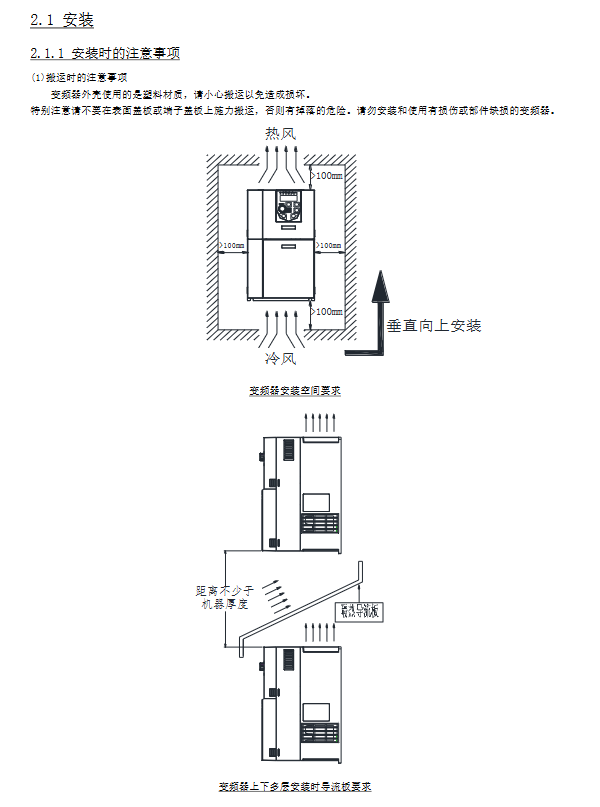
Installation specifications:
Method: Vertically installed on non combustible metal walls, with fixing screws bearing the weight of the body
Space: Reserve ≥ 10cm of heat dissipation space on the top, bottom, left, and right sides, and add insulation deflectors for multi-layer installation
Inside the control cabinet: Reasonable layout of ventilation fans to avoid hot air circulation
2. Wiring specifications
Main circuit terminal description
|Terminal markings | Function | Wiring requirements|
|R/S/T (three-phase)/L/N (single-phase) | Power input | 380V for three-phase or 220V for single-phase, with residual current circuit breaker required|
|U/V/W | Motor output | Connecting three-phase motors, if the wiring length exceeds 100m, an output reactor needs to be added|
|P (+)/PB | Brake resistor connection | Select the minimum resistance value (13.6~300 Ω) according to the model, wiring ≤ 5m|
|G | Grounding | Independent grounding, wire diameter ≥ power wire|
Control circuit terminal:
7.5kW and below: 5-way DI, 1-way AI, 1-way AO, 1-set relay output
11kW and above: 6-way DI (including 1 high-speed pulse input at 100kHz), 2-channel AI, 2-channel AO, 2-channel relay output
Recommended wire diameter and accessories
|Inverter model | Power line (mm ²) | Control return line (mm ²) | Grounding wire (mm ²) | Recommended accessories|
|CsH100-004SF (0.4kW) | 2.5 | 1.5 | 1.5 | Braking resistance ≥ 220 Ω/100W|
|CsH100-110HF (11kW) | 6.0 | 1.5 | 6.0 | Input Reactor, Noise Filter|
|CsH100-220HF (22kW) | 10 | 1.5 | 10 | Output reactor, braking resistor 13.6 Ω/3.7kW|
Operation and Handling
1. Four core operating modes
table
Applicable scenarios for setting key parameters of operation mode control source
Operator Control Body Operator F0-04=0 (operator command), F0-06=1 (preset frequency) Single machine debugging, manual operation
Terminal control DI/AI terminal F0-04=1 (terminal command), F0-06=2 (AI1 given) External switch/potentiometer control
Multi speed control, multi speed terminal F0-06=4 (multi speed), FC-00~FC-15 set speed, fixed speed switching (such as pipeline)
485 communication control upper computer (PLC, etc.) F0-04=2 (communication command), F0-06=7 (communication given) centralized control, multi device linkage
2. Key operational procedures
Motor parameter self-tuning (recommended for vector control):
Set motor nameplate parameters (F4-01~F4-06: power, voltage, current, etc.);
Select self-tuning mode (F4-00=1 static/2 rotation);
Press the RUN button on the operator to start, and it will automatically adjust for up to 2 minutes to update parameters such as motor inductance and resistance.
Trip reset:
After the fault occurs, the frequency converter cuts off the output and displays a fault code;
After investigating the cause, press the STOP/RESET button or reset through the DI terminal (assigned the "fault reset" function);
If the trip still occurs, power off for 10 minutes (confirm that the bus voltage is<45V) before restarting.
485 communication function
1. Communication specifications
table
Project parameter setting method
Protocol Modbus RTU (Slave) Fixed
Baud rate 300/600/1200~38400bps F8-00 setting (default 9600bps)
Data format: 8-bit data bit, 1/2 stop bit, no/even/odd parity F8-01 setting (default 8, N, 1)
Communication address 0~247 (0 is the broadcast address) F8-02 setting (default 1)
Maximum Connection Number 247 Operator Settings
2. Core communication functions
Register read and write:
Read register (03h): Read up to 12 at a time, such as reading the set frequency (address 1001h) and output current (1005h);
Write register (06h): Write one at a time, such as writing forward instruction (address 2000h=0001h), set frequency 45.00Hz (address 9000h=1194h).
Common register addresses
|Register Address (hex) | Function | Read/Write Properties|
|1001 | Set frequency (0.01Hz) | Read|
|1005 | Output current (0.1A) | Read|
|2000 | Control command (forward/reverse/stop) | Write|
|8000 | Fault Status | Read|
Fault handling and maintenance
1. Common fault codes and countermeasures
table
Fault code, fault name, core cause, handling measures
Err04 acceleration overcurrent acceleration time is too short, motor short circuit, load sudden change 1. Increase acceleration time (F0-23); 2. Check the insulation of the motor; 3. Check the load
Err09 deceleration overvoltage, short deceleration time, no brake resistor connected. 1. Increase deceleration time (F0-24); 2. Configure braking resistors; 3. Activate overexcitation braking
Err14 motor overload load is too large, and the overload protection gain is improper. 1. Reduce the load; 2. Adjust F9-01 (overload protection gain); 3. Check the heat dissipation of the motor
Err27 communication fault wiring error, parameter mismatch 1. Check 485+/485- wiring; 2. Confirm that the baud rate/address is consistent; 3. Add a terminal resistor (120 Ω)
2. Maintenance and upkeep
Daily maintenance:
Inspection: Motor sound/vibration, fan operation, ambient temperature;
Cleaning: Remove dust and oil stains from the surface of the frequency converter and fan.
Regular check (recommended every 6 months):
Tighten the wiring terminals, check the smoothness of the air duct, and test the insulation of the main circuit (500V megohmmeter).
Replacement of lifespan components:
Cooling fan: 2-3 years (to be replaced in case of abnormal noise/stoppage);
Electrolytic capacitor: 4-5 years (to be replaced in case of leakage/bulging).
Product specifications and core functions
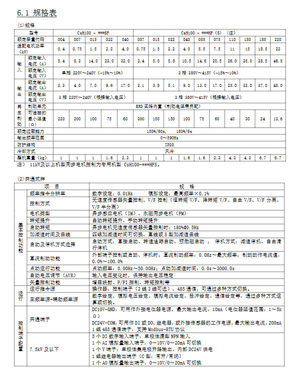
1. Core electrical specifications
table
Project specification parameters
Suitable motor power: 0.4kW~22kW (SF single-phase model), 0.75kW~22kW (HF three-phase model)
Input voltage: single-phase 220V (-15%~+10%), three-phase 380V (-15%~+10%)
Output frequency range 0~590Hz (resolution 0.01Hz)
Rated overload capacity 150% rated current/60s, 180% rated current/6s
Control mode V/F control (constant torque/reduced torque), sensorless vector control
Starting torque asynchronous motor vector control: 180% @ 0.5Hz
2. Core application functions
Basic functions: multi speed (16 speed), S-shaped acceleration and deceleration, dead zone for forward and reverse rotation, frequency jump (avoiding resonance);
Advanced features: PID control (closed-loop regulation), swing frequency control (textile winding), simple PLC (16 segment program), master-slave control, sleep wake-up;
Protection function: 46 types of protection (overcurrent, overvoltage, undervoltage, overload, phase loss, short circuit to ground, etc.), supporting automatic fault reset (up to 20 times).
Parameter Setting System
Parameter group classification (8 groups in total):
F0~FF: Basic functions (control mode, operation command source, acceleration and deceleration time);
H0~H3: Second motor parameters (independently set two sets of motor parameters);
L0~L6: Enhanced functions (master-slave control, brake control, sleep function);
U0~U1: Monitoring parameters (fault records, operation status monitoring).
Parameter operation optimization:
Supports 3 menu modes (basic/user customized/initial value change);
Users can customize 31 commonly used parameters (L1 group) and support password locking (F7-49).
- YOKOGAWA
- Reliance
- ADVANCED
- SEW
- ProSoft
- WATLOW
- Kongsberg
- FANUC
- VSD
- DCS
- PLC
- man-machine
- Covid-19
- Energy and Gender
- Energy Access
- Renewable Integration
- Energy Subsidies
- Energy and Water
- Net zero emission
- Energy Security
- Critical Minerals
- A-B
- petroleum
- Mine scale
- Sewage treatment
- cement
- architecture
- Industrial information
- New energy
- Automobile market
- electricity
- Construction site
- HIMA
- ABB
- Rockwell
- Schneider Modicon
- Siemens
- xYCOM
- Yaskawa
- Woodward
- BOSCH Rexroth
- MOOG
- General Electric
- American NI
- Rolls-Royce
- CTI
- Honeywell
- EMERSON
- MAN
- GE
- TRICONEX
- Control Wave
- ALSTOM
- AMAT
- STUDER
- KONGSBERG
- MOTOROLA
- DANAHER MOTION
- Bentley
- Galil
- EATON
- MOLEX
- Triconex
- DEIF
- B&W
- ZYGO
- Aerotech
- DANFOSS
- KOLLMORGEN
- Beijer
- Endress+Hauser
- schneider
- Foxboro
- KB
- REXROTH
- YAMAHA
- Johnson
- Westinghouse
- WAGO
- TOSHIBA
- TEKTRONIX
- BENDER
- BMCM
- SMC
- HITACHI
- HIRSCHMANN
- XP POWER
- Baldor
- Meggitt
- SHINKAWA
- Other Brands
- UniOP
- KUKA
- IBA
- Beckhoff
-
LTI SC52.0040.0012.0000.0 - Servo Drive
-
Lti SC52.0040.0012.0000.0 - Servo Drive
-
Milton Industries LTI Tool By Milton LT1240 - 1/2" Drive Lugnut Remover
-
LTi Drives SO84.200.P030.0000.0-W - Servo Spindle Drive
-
LTI DRIVES LSP08-035-320-30-B0R1PY170 - Servo Motor
-
LTI DRIVES SE84.200.SC00.0001.0-W - Servo Drive
-
Lust CDE34.005.W2.2 - Lti Drives Controller
-
LTi SO84.012.0030.0011.2 - ServoOne Servo Drive
-
LTi Drives SO CM-P.0010.11.00.0 - Servo Drive Controller
-
LTi CDE34.017.W3.0 - Servo Drive
-
LTI Drives CDB32.004, C2.0,SH - Positioning Controller
-
LUST CM-CAN1 - LTi DRIVES Communication Module
-
LTi SO84.012.1030.0000.2 - Servo Drive
-
LTI MOOG CDE54.044 - PITCHMASTER FREQUENCY CONVERTER 181-01019
-
MOOG LTI 181-01019 CDE54.044 - PITCHMASTER FREQUENCY CONVERTER
-
Lust LTi Drives CDE34.010,D2.0 - Servo Drive Controller
-
LTI SO84.032.0003.0101.2 - Servo Drive
-
Seagate 9CC132-302 Harris LTI-CS IRT-34-0021-01 - Hard Drive 160GB
-
LTI SO84.032.0003.0001.2 - Servo Drive
-
LTI SO24.007.0070.0000.1 - SERVO CONTROLLER
-
LTi drive CDA32.003.C3.0.H05-01.PC1 - Servo Drive
-
LTI SO84.016.0030.0000.2 - SERVO CONTROLLER
-
LUST LTI CD A34.008,W1.4, BR - SERVO DRIVE
-
MOOG LTI 181-01019 CDE54.044 - PITCHMASTER FREQUENCY CONVERTER
-
LTI MOOG 181-01019 - PITCH Master Servo Drive CDE54.044
-
LTI SERVO ONE SO84.045.0030.0001.2-W - Drive
-
LUST LTi SO84.032.0040.0000.2 - SERVO ONE DRIVE
-
LTi Drives LSH-074-2-30-3 20/T1,G6.1M - SERVO MOTOR
-
LTI SO84.016.0000.0101.2 - servo drive
-
LTI SA54.0550.0033.0000.0 - Servo Drive
-
LTI SA54.0550.0033.0000.0 - Servo Drive
-
LTI LT 4850 - 3/8" Drive 3-Pc Twist Socket Transmission Drain Plug Removal System
-
LTI Tools LT4400-30 Lock Technology - 3/4" Twist Socket 1/2" Drive Lugnut Remover
-
LTI Tools LT-1400C - 1/2 Drive Wheel Torque Extension Tool
-
LTI Tools LT1250 - 1/2" Drive Dual Sided Socket Lug Nut Remover Tool
-
LTI SO84.032.0003.0101.2 - Servo Drive
-
LTI MOOG 181-01019 - PITCH Master Servo Drive CDE54.044
-
MOOG LTI 181-01019 CDE54.044 - PITCHMASTER FREQUENCY CONVERTER
-
MOOG LTI 181-01019 CDE54.044 - PITCHMASTER FREQUENCY CONVERTER
-
MOOG LTI 181-01019 CDE54.044 - PITCHMASTER FREQUENCY CONVERTER
-
LTI SA54.0550.0033.0000.0 - Servo Drive
-
LTI Tools LT-4800 - 7 Piece Twist Socket 3/8" Drive Oil Drain Plug Removal Set
-
LTI SA54.0550.0033.0000.0 - Servo Drive
-
LTI Drive SO24.007.00300000.0 - Servo Drive
-
LTI TOOLS LTI 1400-I - Drive Wheel Torque Extension
-
LTI Tools LT4400-3 - 3/4" 19mm Twist Socket 1/2" Drive Lugnut
-
LTI TOOLS LTI 1400-BB - Drive Wheel Torque Extension
-
LTI SO84.032.0003.0101.2 - Servo Drive
-
LTI Tools LT-4512 - 3/8" Drive 12mm Twist Socket
-
LTI MOTION Luster SO84.032.0003.0001.2 - Servo Drive
-
LTI Tool By Milton LT1600P - 1" Drive Torx Stick
-
LTI Lust VF1424L,HF,OP2,S56 - Variable Frequency Drive
-
LUST CDA32.004,C1.4,H08,B0 - SERVO DFRIVE CM-CAN1 Module
-
LTI SO84.045.0002.0001.2-W - Drive
-
LTI Lust VF1404M,C9,PT1,BR1 - Inverter Type VF1404M
-
LTI SA54.0550.0033.0000.0 - Servo Drive
-
LTI Tools LT-1400C - 1/2" Drive Wheel Torque Extension
-
Lust LTI DRiVES CDA32.006, C3.0, H09 - Variateur De Fr茅quence Frequency Inverter
-
LTI MOOG CDE54.044 - PITCH master SERVO DRIVE
-
LTI MOOG CDE54.044 - PITCH master SERVO DRIVE
-
LTI SO84.143.0020.0101.2-W - servo drive
-
LTI MOTION SC34.0200.0011.0000.0 - Servo drives
-
LTI SO84.032.0003.0001.2 - Servo Drive
-
LTI DRIVES GmbH MS100 - Assembly Set Mounting Kit
-
LTI SO84.032.0003.0001.2 - Servo Drive
-
LTI SO84.032.0003.0001.2 - Servo Drive
-
LTI MOTION SO84.032.0003.0101.2 - servo drive
-
LTI SO84.032.0003.0101.2 - Servo Drive
-
LTI MOOG CDE54.044 - PITCH master SERVO DRIVE
-
LTI MOTION CDE32.004.C2.4 - Servo drives
-
LTI CDD34.032锛學x.x锛孊R锛孭C1 - Servo Drive
-
Lust LTI DRiVES CDA32.006, C3.0, H09 - Inversor De Frecuencia Frequency Inverter
-
Lust SO84.008.0030.1000.0 - Servo One LTi Drive
-
LTI MOTION SO84.032.0003.0101.2 - Servo drives
-
LUST LTi CDA32.004,C1.4 - SERVO DRIVE
-
LTI MOOG CDE54.044 - PITCH Master SERVO DRIVE
-
LTI KEBA CDB32.004 C2.7, SH - PN: 08673530 Frequency Inverter
-
LTI Tools LT-1400C - 1/2" Drive Wheel Torque Extension
-
LTI LT1400-E - 1/2" Drive Wheel Torque Extension
-
LTI MOOG 181-01019 - PITCH master SERVO DRIVE CDE54.044
-
LTI LSN-097-0510-30-560/T1 - Actuator Motor
-
LTI Tools LT 4800 - 7 Piece 3/8" Drive Twist Socket Oil Drain Plug Removal System
-
LTI DRIVES GmbH MS100 - MONTAGESET Assembly Set Mounting Kit
-
Lti SC52.0040.0012.0000.0 - Servo Drive
-
LTI DRIVES GmbH MS100 - Juego De Montaje Assembly Set Mounting Kit
-
LTi DSM4-14.2-21R83-200 - Drives servomoteur Servo Motor
-
MOOG CDE 54.044.GDA - Pitch Master Industrielle Turbine Lti Drive
-
LTI SO24.004.0030.1000.0 - Servo Drive Controller
-
Lti MOOG CDE54.044 - Pitch Master Servo Drive
-
Lust LTI DRiVES CDA32.006, C3.0, H09 - Inverter
-
LTI MOTION GMBH CDB34.006,W3.0,PC1,H39 - Frequency inverter
-
LTI SO84.032.0003.0001.2 - Servo Drive
-
MOOG CDE 54.044.D - Pitch Master Industrielle Turbine Lti Drive
-
LTI TOOLS LT-1460 - 1/2" DRIVE WHEEL TORQUE EXTENSION KIT 5 PIECE SET
-
Lust Cdb32.003, C2.4 - Lti Drives Servoregulador Frecuencia Servo Controller Inverter
-
Lust LTI DRIVES CDA32.006, C3.0, H09 - Frequency Inverter
-
Lust Lti SO82.004.0030.0000.2 - Servo Drive
-
LTI MOTION SC34.0200.0011.0000.0-SL - Servo drives
-
LTI MOTION SA54.0075.0033.0000.0 - Servo drives
-
LTI MOTION SC32.0075.1011.0000.0 - Servo drives
-
LTI Servo-One Junior SO22.006.0080.1000.0 - Servo Controller Servoregler
-
LUST CDA32.004, C1.4, H08, B0 - Servo Drive & LTI CM-CAN1 Module
-
LTI DRIVES LSP08-035-320-30-B0R1PY170 - Servo Motor
-
LUST LTI CDA32.004,C1.4.H08.B0 - SERVO CONTROLLER DRIVES
-
LUST LTi DRiVES CDS44.072LC1.2 - Servo Drive
-
Lti Servo-One Junior SO22.006.0082.1000.0 - Servo Controller Servoregler
-
LUST CDA32.008,C2.0,HF - Lti DRIVES Spindle Drive Inverter
-
LTI SO22.003.0082.0000.0 - Servo Drives One junior Servo Controller Servoregler
-
Lust Lti Drives CM-CAN1 - Communication Module
-
LUST Lti Drives Vf1202s, G8, I6 - Frequency Inverter Drive
-
LTI DRIVES BR-090.03.540.UR.H38 - Bremswiderstand Brake Resistor
-
LTi DRIVES PM-E40.2DRA054P - Wind Turbine Pitch Control Inverter
-
LTi Drives GmbH br-110.01.540-UR - Brake Resistor
-
LTI Drives LSN-097-0960-30-0560/T1,S4,B - Servo Motor
-
LUST CDA34.006.C2.0 - LTI Drives Servoregler
-
LUST LTI DRIVES SERVO ONE JUNIOR SO24.002.0020.0000.1 - Servo Drive Controller
-
LTI MOTION SO84.032.0003.0001.2 - Servo drives
-
LTI DDTD750V2-120 - IBOP ACTUATOR CYLINDER FOR TOP DRIVE
-
LTI CDE32.004, C2.4 - SERVO DRIVE
-
LUST LTI DRIVES CDD34.017 W3.4PC1 - Servo Drive Controller
-
LTI CDA3208,C3,0,HF - AC SERVO DRIVE
-
LUST LTI DRIVES LSH-074-3-30-560/T1,G6.1S - SERVO MOTOR
-
LUST Lti CDB32.004.C2.4.SH - AC Servo Drive
-
LTi CDA32.006, C3.0, H09 - Servo Drive
-
LTI SO22.003.0010.0000.0 - Servo Drive Servo one junior Servoregler Controller
-
LTi Drives DSM4-14.2-21R83-200 - Servo Motor
-
LUST Lti Drives Lsh-097-1-30-560/T1, 1R - Servomotor
-
LTI 1237 - 7 Piece 1/2" Drive Flip Socket Set

K-JIANG

Add: Jimei North Road, Jimei District, Xiamen, Fujian, China
Tell:+86-15305925923