
K-WANG


Emerson DeltaV SIS Logic Solver (SLS1508)
The world's first intelligent SIS logic solver: communicates with intelligent field devices through the HART protocol to diagnose faults in field instruments and final control components in advance (according to research, such faults account for more than 85% of SIS faults), avoiding false tripping, improving process availability, and reducing full lifecycle costs.
Emerson DeltaV SIS Logic Solver (SLS1508)
Core positioning and core advantages
The DeltaV SIS Logic Solver (SLS1508) is the core component of Emerson's Intelligent Safety Instrumented Systems (SIS), designed specifically for industrial process safety protection and meeting SIL 1-3 safety functional requirements. Its core advantages can be summarized into six key features:
The world's first intelligent SIS logic solver: communicates with intelligent field devices through the HART protocol to diagnose faults in field instruments and final control components in advance (according to research, such faults account for more than 85% of SIS faults), avoiding false tripping, improving process availability, and reducing full lifecycle costs.
Integrated but independent with the control system: strictly follow safety standards, use dedicated hardware, software, and networks to implement safety functions, and eliminate the impact of common cause failures; Simultaneously achieve seamless integration of configuration, maintenance, and operating environment at the workstation level, balancing security and usability.
Easy to comply with IEC 61511 standard: provides strict user management functions, automatically verifies data for changes initiated by the human-machine interface (HMI) (such as trip limit modification), ensures accurate data writing into the target logic solver, and meets the strict requirements of the standard for change control.
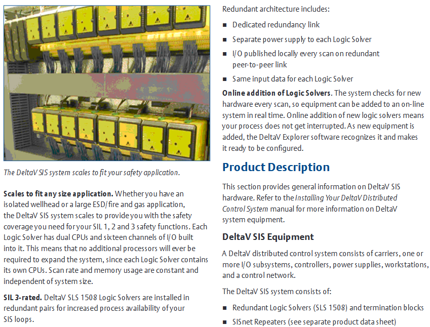
Suitable for any scale of application: Whether it is an isolated wellhead or a large emergency shutdown (ESD)/fire and gas system, it can be flexibly expanded to cover SIL 1-3 safety functions; Each logic solver is equipped with dual CPUs and 16 I/O channels, allowing for system expansion without the need for additional processors. The scanning rate and memory usage are not affected by system size and remain stable.
SIL 3 certification and redundant architecture: The SLS1508 logic solver meets SIL 3 application requirements with a single unit, and the availability is higher when installed in pairs with redundancy; The redundant architecture includes dedicated redundant links, independent power supply, I/O redundant peer-to-peer links for real-time release, and dual machine shared input data to ensure reliable system operation.
Support for online addition of logic solvers: The system automatically detects new hardware every scanning cycle and can add devices to the online system in real-time without interrupting the process; Once the newly added device is recognized by DeltaV Resource Manager, it can be directly configured, greatly improving the flexibility of system expansion.
Core components and functional details of the product
(1) Core hardware components and system architecture
Component Name Function Description Key Features
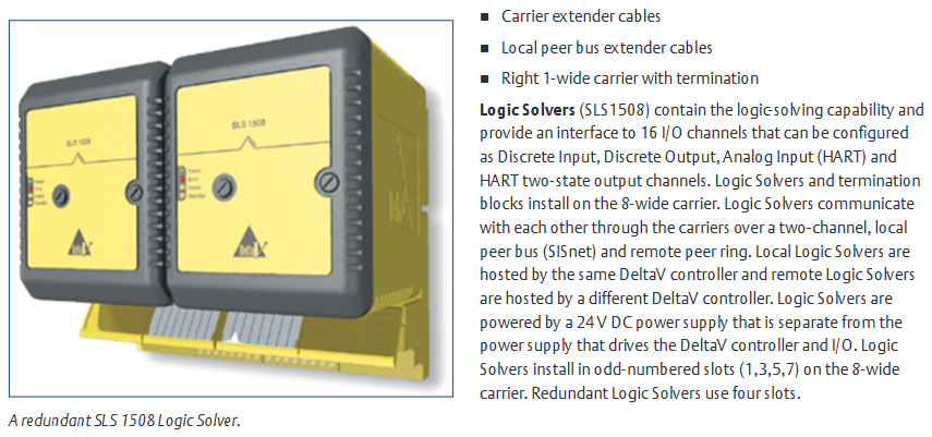
SLS1508 logic solver core safety logic operation unit, provides I/O interface with built-in dual CPU, 16 configurable I/O channels (discrete input/output, analog input (HART), HART dual state output), supports single SIL 3 application, and occupies 4 slots for redundant paired installation
The redundant terminal block connects the on-site wiring and logic solver to adapt to the SLS1508 redundant architecture, enabling redundancy without the need for additional control strategy configuration. The system automatically identifies redundant pairs
SISnet repeater extends the communication range of SISnet and realizes remote logic solver communication through fiber optic ring network. It is divided into two independent fiber optic rings, primary and backup. Please refer to the separate product manual for details
The carrier extension cable extends the local bus power and signal connection between 8-wide carriers, ensuring signal transmission between the controller, logic solver, and SISnet repeater
Local peer-to-peer bus extension cable extends SISnet communication between logic solvers on different carriers, supports interconnection of logic solvers across carriers, and builds a local SISnet network
The wide terminal carrier terminates the local peer-to-peer bus installed at the end of the carrier chain, providing SISnet bus terminal matching to ensure stable communication
The 8-width carrier carries logic solvers, SISnet repeaters, and other components. The logic solvers are installed in odd numbered slots (1/3/5/7) and support connecting multiple carriers through expansion cables
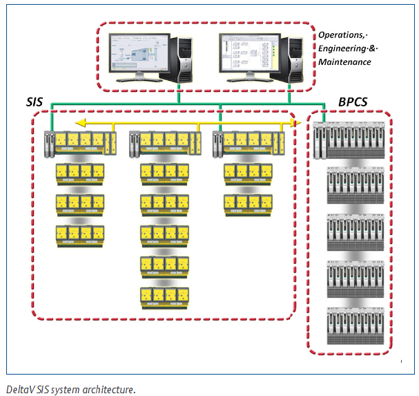
(2) Communication Network Design
Control Network: Implement communication between DeltaV network nodes, as detailed in the DeltaV Digital Automation System Installation Manual.
Local Bus: connects DeltaV controllers with logic solvers, SISnet repeaters, and transmits control and configuration signals.
Local Peer to Peer Bus (SISnet): a dual channel bus where logic solvers communicate with each other and with local SISnet repeaters through a carrier, and the same message is broadcasted on both channels; The two ends of the bus need to be terminated (the left end through a 2-wide power/controller carrier, and the right end through a 1-wide terminal carrier), and the repeater can be flexibly installed at any position on the bus.
Remote Peer Ring: SISnet repeaters hosted by different controllers communicate through fiber optic ring networks. Local repeaters aggregate global variable messages and transmit them along the ring network. Receiver repeaters broadcast and forward them on the local SISnet, while global messages are transmitted only once along the ring network. The primary and backup repeaters form independent fiber optic rings.
(3) Unique redundancy mechanism
Redundant operation mode: The redundant SLS1508 dual machine always runs in parallel, reading I/O inputs, executing safety logic, and driving outputs, without distinction between master and backup/master-slave; Only one (Active state, indicator light on) communicates with the workstation and SISnet, while the other (Standby state) only connects to SISnet.
Fault handling: When a single machine detects a fault, it automatically enters a failure state, and all output channels are powered off, but it does not affect the operation of another machine (continuing to read and write I/O, executing logic), and redundant switching is completely undisturbed; In safe areas, faulty modules can be replaced with electricity, while in hazardous areas, specific installation procedures must be followed.
Integrity alarm: Real time monitoring of redundant pair status, triggering alarm scenarios including: hardware failure of logic solver, communication failure between logic solver and SISnet, communication failure between redundant pairs, communication failure between logic solver and DeltaV controller, and removal of logic solver from carrier; Alarm information and device status can be viewed in the diagnostic browser.
Automatic verification testing: Redundancy can be configured for automatic verification testing. After setting the testing interval, the system will automatically execute and issue a warning to the operator before testing to ensure the effectiveness of safety functions.
(4) Sequence of Events (SOE) function
Basic function: Automatically generate events when executing function blocks during the module scanning cycle, with a timestamp resolution of<1ms, and record them in the event log in the order of occurrence; Standard functional blocks (input block, voting block, cause and effect block, etc.) can automatically generate events (such as I/O faults, trip limit triggering, first output signal) without special configuration, and record the simulated values and triggering conditions during tripping.
First out positioning: When the factory emergency stops, the "first out trip" signal in the event log can be filtered to quickly locate the first input that triggers the trip, simplifying fault diagnosis.
High resolution extension: If higher temporal resolution (0.25ms) is required, the channel can be simultaneously connected to SLS1508 and DeltaV discrete input SOE cards.
Hardware specifications and I/O channel parameters
(1) General Environment and Physical Specifications
1. SLS1508 Universal Environment Specification
Category parameter details
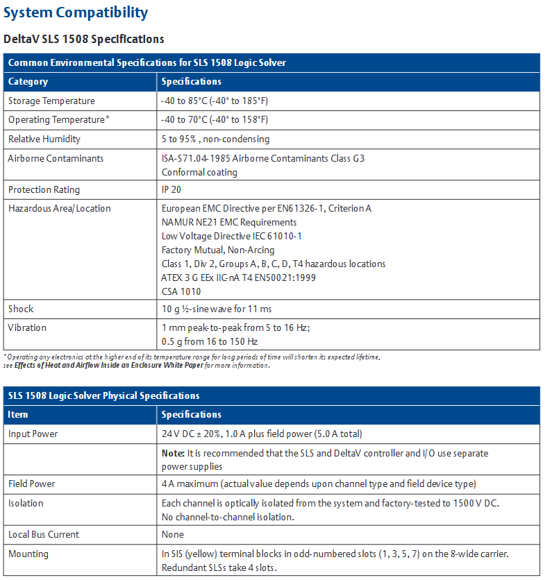
Working temperature -40~70 ° C (-40~158 ° F), long-term high-temperature operation shortens lifespan
Storage temperature -40~85 ° C (-40~185 ° F)
Relative humidity 5%~95% (no condensation)
Pollutant level ISA-S71.04-1985 G3 level (with conformal coating)
Protection level IP20
Hazardous Area Certification: European EMC Directive (EN61326-1, Criterion A), NAMUR NE21 EMC Requirements, Low Voltage Directive (IEC 61010-1), FM Class I Div 2 (Groups A-D, T4, No Arc) ATEX 3 G EEx IIC-nA T4(EN50021:1999)、CSA 1010
Anti impact 10g half sine wave (continuous for 11ms)
Vibration 5-16Hz (1mm peak to peak), 16-150Hz (0.5g)
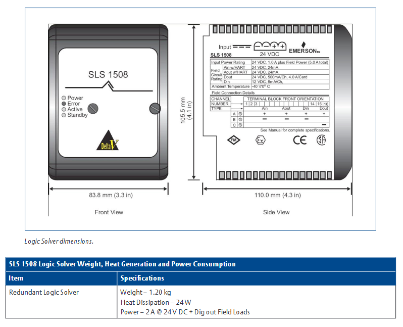
2. SLS1508 Physical and Electrical Specifications
Project parameter details
Input power supply 24V DC ± 20%, 1.0A (basic power consumption)+on-site power supply (total power consumption 5.0A); Suggest using an independent power supply with DeltaV controller/I/O
The maximum on-site power supply is 4A (actual value depends on channel type and on-site equipment)
Isolation level: Each channel is optically isolated from the system (1500VDC factory test), and there is no isolation between channels
No local bus current
Installation method: SIS (yellow) terminal block on a wide carrier with odd numbered slots; Redundant occupation of 4 slots
Redundancy for weight 1.20kg
Redundancy for heat consumption of 24W
Redundancy for 24V power consumption DC@2A +Digital output on-site load
Dimensions (Front/Side) 83.8mm (3.3 inches)/110.0mm (4.3 inches)
(2) Detailed parameters of I/O channels
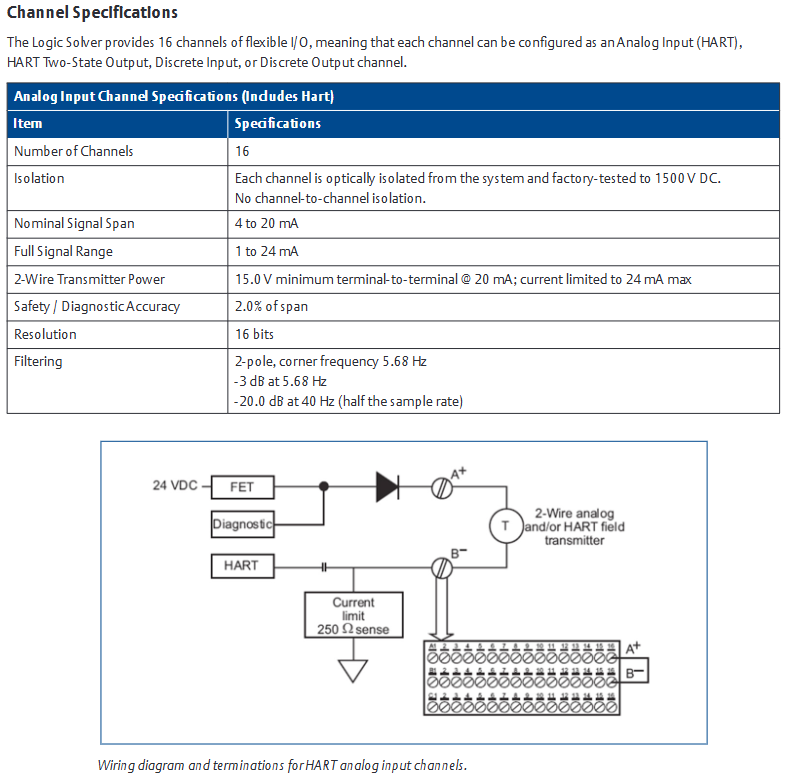
1. Analog input channel (including HART)
Project parameters
Number of channels 16
Isolate each channel from the system's optical isolation (1500VDC test), with no isolation between channels
Nominal signal range 4~20mA
Full signal range 1-24mA
When the 2-wire transmitter is powered by 20mA, the minimum voltage between terminals is 15.0V, and the maximum current limit is 24mA
2.0% of the safety/diagnostic accuracy range
Resolution 16 bits
Filter 2nd order, cut-off frequency 5.68Hz (-3dB), at 40Hz (1/2 of sampling rate) -20.0dB
2. HART dual state output channel
Project parameters
Number of channels 16
Isolate each channel from the system's optical isolation (1500VDC test), with no isolation between channels
The nominal signal range is 20mA for conduction and 0 or 4mA for shutdown (configurable)
Full signal range 0~24mA
5.0% of the safety/diagnostic accuracy range
Resolution of 12 bits
Compliant voltage 20mA@600 Ω load
Triggered when the open-loop detection output deviates from the configured value by 15% and the current is less than 1.0mA
3. Discrete input channel
Project parameters
Number of channels 16
Isolate each channel from the system's optical isolation (1500VDC test), with no isolation between channels
Conductivity detection ≥ 2mA
Shutdown detection ≤ 1.65mA
The input impedance is about 1790 Ω
Input compatibility NAMUR sensor (12V), dry contacts, dry contacts with terminal resistors
Line fault detection (short circuit, optional) with resistance<100 Ω and current>6mA
Line fault detection (open circuit, optional) with current<0.35mA when resistance>40k Ω
The fault detection configuration requires channel level activation, and the dry contact requires an external 12k Ω parallel resistor (open circuit detection) and a 2.4k Ω series resistor (short circuit detection). The NAMUR sensor does not require an external resistor
4. Discrete output channels
Project parameters
Number of channels 16
Isolate each channel from the system's optical isolation (1500VDC test), with no isolation between channels
Output voltage: On site power supply voltage -2V
On site power supply with continuous 0.5A per channel, maximum 4.0A per card
Output load 56~3500 Ω
Turn off leakage current open-loop test on: 7.8mA; open-loop test off: typical 4.5 μ A, maximum 10 μ A
Short circuit protection current limit typical 2.0A
Line fault detection (short circuit): Under 24V DC on-site power supply, the resistance is less than 5 Ω for more than 1 second
Line fault detection (open circuit): Under 24V DC on-site power supply, resistance>25k Ω (open circuit detection),<3.5k Ω (no open circuit detection)
Pulse testing is recommended to be enabled (apply 1ms of 24V DC pulse every 50ms), and devices such as solid-state relays that do not support it can be disabled
Ordering Information and Preconditions
(1) Core Product Order List
Product Description Model
DeltaV SLS1508 Redundant Logic Solver (including Terminal Block) VS3202
1 wide SISnet terminal component (including right expansion card and 2 terminal resistors) VS6051
SIS database extension VS1508
8-width carrier with expansion cable assembly (including left and right expansion cards, 2 logic solver communication buses coaxial, 1 carrier backplane communication cable) VE4050E1C2
2 Wide Carrier (Improved Type, Including Bus Terminal) VE3051C0
(2) Pre requirements
Software version: DeltaV v8.3 or above is required.
2-Width Power/Controller Carrier: Upgraded version after 2004 (with white rectangular markings on the board, located between the power module and MD controller), model KJ4001X1-BA3 and above; The old version (marked with white dots) does not support downloading logic solver programs.
MD controller: Model must be 12P2093X082 or above, early models do not support DeltaV SIS system.
- YOKOGAWA
- Reliance
- ADVANCED
- SEW
- ProSoft
- WATLOW
- Kongsberg
- FANUC
- VSD
- DCS
- PLC
- man-machine
- Covid-19
- Energy and Gender
- Energy Access
- Renewable Integration
- Energy Subsidies
- Energy and Water
- Net zero emission
- Energy Security
- Critical Minerals
- A-B
- petroleum
- Mine scale
- Sewage treatment
- cement
- architecture
- Industrial information
- New energy
- Automobile market
- electricity
- Construction site
- HIMA
- ABB
- Rockwell
- Schneider Modicon
- Siemens
- xYCOM
- Yaskawa
- Woodward
- BOSCH Rexroth
- MOOG
- General Electric
- American NI
- Rolls-Royce
- CTI
- Honeywell
- EMERSON
- MAN
- GE
- TRICONEX
- Control Wave
- ALSTOM
- AMAT
- STUDER
- KONGSBERG
- MOTOROLA
- DANAHER MOTION
- Bentley
- Galil
- EATON
- MOLEX
- Triconex
- DEIF
- B&W
- ZYGO
- Aerotech
- DANFOSS
- KOLLMORGEN
- Beijer
- Endress+Hauser
- schneider
- Foxboro
- KB
- REXROTH
- YAMAHA
- Johnson
- Westinghouse
- WAGO
- TOSHIBA
- TEKTRONIX
- BENDER
- BMCM
- SMC
- HITACHI
- HIRSCHMANN
- XP POWER
- Baldor
- Meggitt
- SHINKAWA
- Other Brands
- UniOP
- KUKA
- IBA
-
LTI Drives CDF30.002.C0.7 Compact Servo Controller 08685963 DC 24V Industrial Module
-
LUST LTI Drives CDB32.008.W2.4.BR.PC1 Servo Drive Industrial Motion System
-
LUST LTI Drives CDB34.003.C2.4.PC1.H15 Servo Motor Driver Industrial Control Unit
-
LUST LTI Drives CDA32.004.C1.4.H08.B0 Servo Drive Mat. 3084456 Industrial Control
-
LUST LTI Drives CDE34.005.W2.2 Industrial Servo Drive Motion Control Unit
-
LUST LTI Drives CDA34.006.W3.0 Servo Drive Software V3.70-04 Industrial Controller
-
LTI Drives CDB32.004.C2.4.SH Servo Drive Compact Motion Controller
-
Woodward 9905-373 - Digital Synchronizer And Load Controller
-
WOODWARD MAGNETIC PICKUPS - Sensor
-
WOODWARD GCP-30 - Steuertafel for Industrial Regulator Genset Control Package
-
WOODWARD GOVERNOR 9907-1183 REV A - 505 ENHANCED TURBINE CONTROL
-
WOODWARD 9907-173 REV B - Module Load Sharing 120 Volt
-
WOODWARD 9907-014 - 2301A controller
-
Woodward 9905-029 - SPM-A Synchronizer Module Rev C
-
WOODWARD 8440-1799 EASYGEN-350 REV B - Genset Controller
-
WOODWARD 5466-258 REV M - SIMPLEX DISCRETE I/O MODULE
-
Woodward 8440-1884 C - Controller Easygen 2500-5
-
Woodward 8441-1153 - Monitoring Unit 250VAC
-
WOODWARD 8406-120 REV G - EGCP-2 DIGITAL CONTROL
-
Woodward 8273-584 - Atlas-ii Digital Control
-
Woodward 8272-582 - APM Motor Control 8272582
-
Woodward 9905-377 Rev. A - 2301A Load Sharing and Speed Control
-
WOODWARD 8272-517 - Pm Motor Control
-
WOODWARD 9905-797 REV.B - DIGITAL SYNCHRONIZER AND LOAD CONTROL DSLC-D
-
WOODWARD 8272-582 - APM MOTOR CONTROL
-
Woodward Seg FP2-8-24 - Emergency Power Telecommunications Module NP2
-
WOODWARD 2001-12E2U1B1S1A - Fuel Shut Off Valve Stop Solenoid Valve 2000-4505
-
Woodward 8440-1884 K - Genset Controller Easygen-2500-5
-
Woodward 9905-760 - Linknet Termination Module
-
Woodward 8404-009 - Proact Digital Plus Front Panel Rev. H
-
Woodward 8271-651 - Digital Speed Reference
-
Woodward 3077-474C - 8605895 5501-031 D Circuit Module
-
WOODWARD 5466-257 REV.-C - NETCON 5000 MODEL REMOTE TRANSCEIVER I/O MODULE
-
Woodward 8273-101 Rev: A - 2301D Digital Load Sharing and Speed Control
-
WOODWARD 8272-799 - 2301A SPEED CONTROL WITH REMOTE REFERENCE REV:C
-
Woodward 8272-517 - PM Motor Control
-
Woodward 8290-048 8290048 Rev. F - Generator Load Sensor
-
woodward 8273-1012 rev c - 2301e Load Sharing and Speed Control
-
WOODWARD 9905-797 - DIGITAL SYNCHRONIZER AND LOAD CONTROL FOR 3 PHASE GENERATORS
-
WOODWARD 8280-3014 - 723 PLUS DIGITAL CONTROL REV NEW
-
WOODWARD 8440-1884 REV G - GENSET CONTROLLER EASYGEN-2500-5/P1
-
Woodward 8272-683 K - Digital Reference
-
WOODWARD 9907-014 - SPEED CONTROL 2301A REV H
-
Woodward Type UG-8 P/N 037260 - Governor R.P.M 1075-1650 Motor KM58-20
-
WOODWARD 9905-970 - LINKNET 6 CHANNEL 100 OHM RTD Rev:J
-
Woodward 9907-1183 Rev C - Steam Turbine Digital SCREEN 505E Turbine Control
-
Woodward 8440-1614 - GCP-30 Genset Control Package, Rev: F, Type 1, E231544
-
Woodward DC11006-304-024 - ACTUOTOR DYNA ACTUATOR - BARBER-COLMAN
-
Woodward 9905-971 - LINKNET 6 CHANNEL 100 OHM RTD Rev:K
-
Woodward DYNK-10249 - Actuator Controller Kit - DYNA 2000
-
Woodward LR21035 - MFR1 MULTI FUNCTION RELAY REV F
-
Woodward 8440-1831 - EASYGEN 3200-5 P/N: REV. G Gererator Controller
-
Woodward 8272-516 - PM MOTOR CONTROL REV J
-
Woodward 8440-2080 - EASYGEN 2000 genset controller EASYGEN-2300-5/P1
-
Woodward 505DE - Digital Control System
-
Woodward 701 - Digital Speed Control 18-40 VDC 4-20 MA
-
Woodward 8440-1799 - EASYGEN-350 REV B
-
Woodward 8272-582 - Apm Motor Control 100-220v AC/DC
-
Woodward 5501-031 D - 3077-474C 8605895 Circuit Module
-
Woodward XD1-T - XD1T55SAT TRANSFORMER DIFFERENTIAL PROTECTION RELAY
-
Woodward 8272-517 - PM Motor Control 220vac
-
Woodward 8934-658 - Repair Kit UG8D Governor
-
Woodward 5437 18 - module netcon derivative analog rev.A
-
Woodward 8272-171 A - Pm Motor Control
-
Woodward MRN3-1/2 - SEG mains uncoupling relay MRN314D mains decoupling relay
-
Woodward 9905-373 - Digital Synchronizer and Load Control 18-40 VDC Rev P
-
Woodward 5431-640 C - Dual Dynamics 1000 Series Speed Control Module
-
Woodward 5501-031 D - 3077-474C 8605895 Circuit Module
-
Woodward 9907-247 - 828 DIGITAL CONTROL
-
Woodward 8440-1855-G - EASYGEN-2200-5 /P1 12/24VDC GENSET CONTROLLER
-
Woodward NC3-2-8 (NO) - GENERATOR CONTROLLER
-
Woodward 8271-467 K - 2301 LOAD SHARING AND SPEED CONTROL PART NO:
-
Woodward 8440-2177 A - SPM-D2-10 Digital Synchronising Controller
-
Woodward LXMG1614E-14-11 - CCFL and UV Lamps Inverter Module
-
Woodward 8270-990 - signal converter
-
Woodward 9905-068 - LOW VOLTAGE 2301A LOAD SHARING & SPEED CONTOL P/N:
-
Woodward 8901-051 - BOOSTER SERVOMOTOR, SINGLE CYLINDER, 2:1
-
Woodward 8444-1024 D - MWS4-55M CONTROL MODULE UNIT
-
Woodward 5448-914 - GCP-20 Genset Control GCP-20 REV D P/n:
-
Danfoss BHA-1 018-1942 - Hydraulic Actuator
-
Woodward 9905-001 L - SPM-A SYNCHRONIZER
-
Woodward 5464-850 - Module
-
Woodward 5501-371 - Micronet Simplex Mpu Aio Rev C
-
Woodward 8272-132 B - POWER SENSOR
-
Woodward 9907-028 - SPM-A Synchronizer
-
Woodward SA-3678-AM-2 - Overspeed Electric Governor, Model ESSE2-AM
-
Woodward E8250-502 - GOVERNOR ACTUATOR
-
Woodward 8440-1884 J - Controller EASYGEN-2500-5
-
Woodward 5441-693 - DIGITAL I/O MODULE -MISSING PART
-
Woodward SA-4450 - Speed Controller APECS 3100 For Magnetic Pickup
-
Woodward 9903-466 - 701 DIGITAL SPEED CONTROL REV G
-
Woodward 1765-843 - Governor Speed Adjusting Motor P/N Type: SMM40 220V AC 50/60Hz
-
Woodward 9905-760 - Linknet Termination Module
-
Woodward 9907-247 - 828 DIGITAL CONTROL UNIT REV K
-
Woodward 5484-721 - motor
-
Woodward 8440-1734 - MFR-2 Rev.A Multi Function Relay MFR-2
-
Woodward CSC3SUWA - Controller
-
Woodward 8440-1667 - REV B SPM-D1010B/XN
-
Woodward 8406-120 - egcp-2 digital control
-
Woodward DPG-2201-002 - DIGITAL CONTROLLER REV D
-
Woodward 8272-516 - Pm Engine Control Rev J
-
Woodward 8440-1831 - EASYGEN 3200-5 P/N: REV. K - WITHOUT ACCESSORIES
-
Woodward 8273-101 - LOAD SHARING & SPEED CONTROL
-
Woodward 8440-1855-G - EASYGEN-2200-5 /P1 12/24VDC GENSET CONTROLLER
-
Woodward 9907-247 - 828 DIGITAL CONTROL UNIT REV K
-
Woodward LR21035 - MFR1 MULTI FUNCTION RELAY REV J
-
Woodward 8404-009 - PROACT DIGITAL PLUS FRONT PANEL REV J
-
Woodward 9905-204 - Rev N SPM-A synchronizer
-
Woodward 8521-367 - UG-8 P/N r R.P.M 750-1280 Governor / UG8
-
Woodward 9907-175 - Load Sharing Module Rev. B
-
Woodward 5464-645 - DRIVER MODULE REV A 2C ACT DRIVE
-
Woodward 8404-009 - PROACT DIGITAL PLUS FRONT PANEL REV J
-
Woodward 9907-175 - Load Sharing Module Rev. B
-
Woodward 8406-102 - Rev A EGCP-2 Digital Control Engine Generator 8406102
-
Woodward EASYGEN-2500-5 - Controller Genset
-
Woodward 8440-2082 - Controller
-
Woodward 8272-516 - PM MOTOR CONTROL REV J
-
Woodward 9905-373 - Digital Synchronizer and Load Control 18-40 VDC Rev P
-
Woodward 5501-429 - Actuator Controller 25mA 2 Channel , (UPP)
-
Woodward 8440-1869 - SPM-D10 Synchronizing System Control-SPM-D10B/PSY4-F-D
-
Woodward 9907-175 - Load Sharing Module Rev. A
-
Woodward 8200-224 - Servo Position Controller
-
Woodward 9906-619 - 723 PLUS DIGITAL CONTROL ( 8280-604 )
-
Woodward 8440-1519 - EASYGEN PART NO: REV: 4
-
Woodward 5501-371 - REV C MODULE- MICRONET SIMPLEX MPU & AIO FTM
-
Woodward EASYGEN-3200-5/P1 - Generator Controller Module Rev F
-
Woodward 8440-1884K - GENERATOR CONTROLLER EASYGEN-2500-5 REV,K
-
Woodward 5466-353 - REV C NETCON MAIN CHASSIS TRANSCEIVER

K-JIANG

Add: Jimei North Road, Jimei District, Xiamen, Fujian, China
Tell:+86-15305925923