
K-WANG


ABB E max series low-voltage molded case circuit breaker (Sace)
ABB E max series low-voltage molded case circuit breaker (Sace)
The ABB E max series low-voltage power circuit breaker (Sace) is an innovative product developed based on over half a century of circuit breaker technology. It has high reliability, easy installation, and flexible adaptability. It has passed UL certification and complies with ANSI low-voltage power circuit breaker standards, covering a rated continuous current range of 800A-5000A and a rated short-circuit current range of 42kA-125kA (480V). It is suitable for distribution systems, industrial equipment, and other scenarios, providing efficient power protection solutions for designers, switchgear manufacturers, installers, and users.
Core product classification and key parameters
1. Model and frame specifications
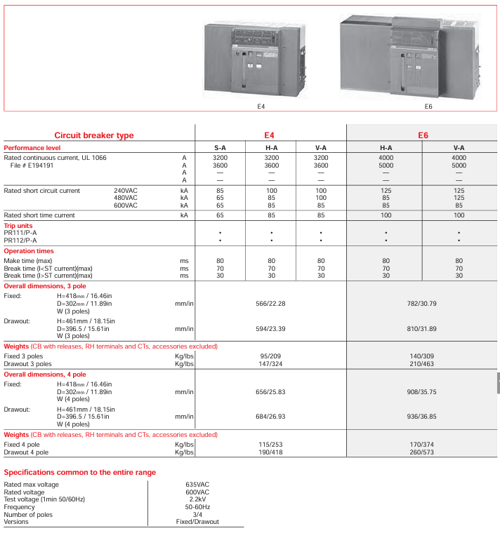
The series includes five models (four sizes): E1, E2, E3, E4, and E6. The differences in core electrical parameters are as follows (taking UL standards as an example):
Model Rated continuous current (A) 480V Rated short-circuit current (kA) Number of poles Installation method Typical weight (kg/lbs, 3 poles fixed)
E1 800-1200 42 3/4 fixed/pull-out 50/110
E2 1200-1600 50 3/4 fixed/extracted 55/121
E3 1200-2500 65-100 3/4 fixed/pull-out 80/176
E4 3200-3600 65-100 3/4 fixed/withdrawable 89/196
E6 4000-5000 85-125 3/4 fixed/withdrawable 125/275
2. General technical specifications (shared by UL and IEC)
Voltage and Frequency: Rated maximum voltage 635VAC, rated operating voltage 600VAC, test voltage (50/60Hz for 1 minute) 2.2kV, applicable frequency 50-60Hz.
Temperature range: Operating temperature -5~+70 ° C, storage temperature -40~+70 ° C, suitable for different temperature zones in industrial sites.
Neutral pole rating: The neutral pole rating for E1-E3 models is 100% of the rated current, and for E4-E6 models it is 50% (special requirements can be consulted with the manufacturer to customize the 100% rating).
Mechanical and electrical lifespan: Mechanical lifespan (under routine maintenance) 20000-25000 operations, electrical lifespan (440VAC) 10000-30000 operations, with a maximum operating frequency of 60 times per hour.

Core functions and structural characteristics
1. Protection and control capability
Release Unit: Standard PR111/P series release, supporting LI (Long Delay Instantaneous), LSI (Long Delay Short Delay Instantaneous), and LSIG (Long Delay Short Delay Instantaneous Ground Fault) protection functions; PR112/P and PR113/P series are optional, suitable for more complex scenarios (such as PR112/PD supporting communication functions).
Operation time: The maximum closing time is 80ms, the maximum opening time (I<short-circuit withstand current) is 70ms, and the maximum (I>short-circuit withstand current) is 30ms. It can quickly respond to faults and reduce equipment damage.
Auxiliary functions: Comes with 2NO+2NC auxiliary contacts (for indication of opening and closing status), spring energy storage/release mechanical indicators, and manual opening and closing buttons; The pull-out model is equipped with a rocking in device with a closed door, a rocking in position indicator, and an anti insertion lock to enhance operational safety.
2. Installation and structural design
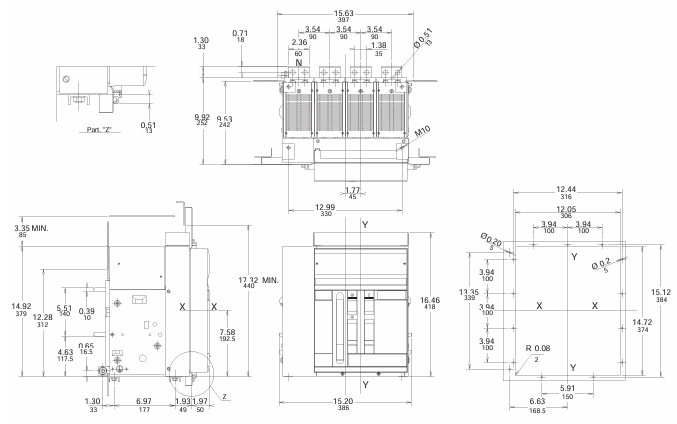
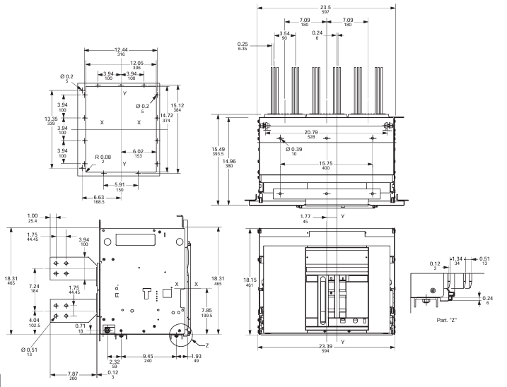
Size and Installation: Fixed 3-pole model with a height of approximately 418mm (16.46 inches) and a depth of 302mm (11.89 inches); The pull-out depth has been increased to 396.5mm (15.61 inches), supporting DIN rail or 19 inch rack installation (requires installation kit).
Terminal and wiring: default rear horizontal terminal, optional rear vertical, front terminal and other types (such as "HH" representing rear horizontal and "HV" representing rear horizontal vertical in the model), suitable for different switchgear wiring requirements; The terminal box is integrated with the current transformer (CT) to simplify on-site wiring.
Redundancy and reliability: The pull-out model is designed with a "mobile part+fixed part" separation, supporting hot swappable replacement; Key components such as sliding contacts and trip units have anti vibration capabilities (7.35 m/S ², 5-500Hz) and comply with ISA S71.04 G3 harsh environment standards.
Product configuration and optional accessories
1. Basic configuration classification
According to the operation mode and function, there are mainly two types of products:
Automatic air circuit breaker: including trip unit and current transformer, supporting fault protection such as overcurrent and short circuit, divided into fixed and withdrawable types, suitable for distribution circuits that require automatic protection.
Non automatic air circuit breaker (switch): no trip unit and CT, only used as a manual or electric power switch, also available in fixed/withdrawable type, suitable for simple circuits that do not require complex protection.
2. Optional attachments (UL and IEC compatible)
Attachment category, specific function and model, example usage
Electrical accessories include shunt release coil (KE6S0, 24VDC), closing coil (KE6C6110-120VAC), and spring energy storage motor (KE6M5110-130VAC/VDC) for remote opening and closing and automatic spring energy storage
Mechanical accessory button protective cover (KE6PG), padlock device (KE6PD1), mechanical counter (KE6MC) to prevent misoperation, lock circuit breaker position, record operation times
Additional auxiliary contacts (KE6A15, 15 sets), position indicator contacts (KE6PS1, 5 sets), extended status monitoring signal, indication of withdrawable circuit breaker position
Interlocking and protective mechanical interlocking (KE6MLP, fixed circuit breaker base), transparent front cover (KE6DC, IP54 protection) achieve multi circuit breaker interlocking control and improve dust and water resistance
Test and Diagnostic Handheld Test Kit (K7TUT, suitable for PR111), Configuration Unit (PR010/T) for on-site testing of trip function and configuration of trip parameters
Model coding rules (taking UL as an example)
Taking "E1S16XXXXXXXXXX" as an example, the key codes have the following meanings to facilitate selection according to requirements:
Frame dimensions: 1=E1 (3 poles), 2=E2 (3 poles), 3=E3 (3 poles), 4=E4 (3 poles), 6=E6 (3 poles); A=E1 (4-pole), B=E2 (4-pole), etc.
Rated current: 08=800A, 12=1200A, 16=1600A, 20=2000A, 32=3200A, 50=5000A.
Breaking ability: B=basic, N=normal, S=standard, H=high, V=extremely high.
Release unit: A=PR111/P-LI, B=PR111/P-LSI, G=PR112/PD-LSI, etc.
Installation method: B=fixed type, D=pull-out type (excluding bracket).
Attachment code: X=no attachment, A=mechanical counter, B=mechanical trip indicator, F=A+B, etc., combined as needed.
Typical application scenarios
Power distribution: used for the main circuit of low-voltage distribution systems, protecting key equipment such as transformers and busbars, and adapting to E4-E6 high current models.
Industrial equipment: provides short-circuit and overload protection for industrial loads such as motors and frequency converters, and E1-E3 small-sized models are suitable for compact layout of switchgear.
Commercial buildings: As the main switch for power distribution, the pull-out design is convenient for later maintenance and replacement.
Compliance and Certification
Safety certification: UL/UL-C certification (applicable to Class I, Groups A-D, Division 2 explosion-proof areas), ATEX certification (Ex nA IIC T4, Zone 2 areas), IEC 60947-2 standard compliance.
Environmental requirements: Compliant with RoHS directive, halogen-free design, reduces harmful substance emissions, suitable for green industrial scenarios.
- YOKOGAWA
- Reliance
- ADVANCED
- SEW
- ProSoft
- WATLOW
- Kongsberg
- FANUC
- VSD
- DCS
- PLC
- man-machine
- Covid-19
- Energy and Gender
- Energy Access
- Renewable Integration
- Energy Subsidies
- Energy and Water
- Net zero emission
- Energy Security
- Critical Minerals
- A-B
- petroleum
- Mine scale
- Sewage treatment
- cement
- architecture
- Industrial information
- New energy
- Automobile market
- electricity
- Construction site
- HIMA
- ABB
- Rockwell
- Schneider Modicon
- Siemens
- xYCOM
- Yaskawa
- Woodward
- BOSCH Rexroth
- MOOG
- General Electric
- American NI
- Rolls-Royce
- CTI
- Honeywell
- EMERSON
- MAN
- GE
- TRICONEX
- Control Wave
- ALSTOM
- AMAT
- STUDER
- KONGSBERG
- MOTOROLA
- DANAHER MOTION
- Bentley
- Galil
- EATON
- MOLEX
- Triconex
- DEIF
- B&W
- ZYGO
- Aerotech
- DANFOSS
- KOLLMORGEN
- Beijer
- Endress+Hauser
- schneider
- Foxboro
- KB
- REXROTH
- YAMAHA
- Johnson
- Westinghouse
- WAGO
- TOSHIBA
- TEKTRONIX
- BENDER
- BMCM
- SMC
- HITACHI
- HIRSCHMANN
- XP POWER
- Baldor
- Meggitt
- SHINKAWA
- Other Brands
- UniOP
- KUKA
- IBA
- Beckhoff
-
ADLINK cPCI-6626 - 6U CompactPCI 2.0 Blades i7-2710QE PCB-I-E-2570=9N41
-
ADLINK MXC-6322D(G) - Industrial Fanless Computer
-
ADLINK cPCI-8168-004 - CompactPci NulPC Motion Control Board 51-36402-0A3
-
ADLINK CPCI-7300[G] - COMPACTPCI Digital I/O Card Data Acquisition
-
ADLINK CPCI-6626/2710/M4G - COMPACTPCI COMPUTER BOARD
-
ADLINK cPCI-8168-009 - cPCI NulPC Motion Control Board
-
ADLINK cPCI-6626/2710/M4G - VME CPU Board Computer Board
-
ADLINK CPCI-R6200(G)-0040 - COMPACTPCI CONTROL BOARD
-
ADLINK CPCI-3840/PM18/M1G(G)-3650 - COMPACTPCI CPU Module Single Board Computer
-
ADLINK cPCI-7248 - 48-CH Opto-22 Compatible Digital I/O Module
-
ADLINK DLAP-211-JNX - NVIDIA Jetson Xavier NX Edge AI Inference Platform
-
ADLINK cPCI-3544 - Series 4-Port RS-422/485 Isolated Serial Communications Card
-
ADLINK CM1-86DX3 - PC/104 SBC Stanley Vortex86DX3 CPU 2GB Ram
-
ADLINK DLAP-211-JNX - NVIDIA Jetson Xavier NX Edge AI Inference Platform
-
ADLINK cPCI-3544 - Series 4-Port RS-422/485 Isolated Serial Communications Card
-
ADLINK CM1-86DX3 - PC/104 SBC Stanley Vortex86DX3 CPU 2GB Ram
-
ADLINK PCI-7433 - switch value acquisition card Isolated Digital Input Card
-
ADLINK PCI-9112 - 51-12252-0D20 Multi-Function Data Acquisition Card
-
ADLINK NUPRO-A301 REV:1.4 - industrial control motherboard PICMG Full-Size SBC
-
ADLINK 51-18502-0A10 - Frame Grabber Image Acquisition Interface Card
-
ADLINK PCI-7296 - 51-12009-0A50 PCB-I-E-925=6DX1 96-CH Parallel Digital I/O Board
-
ADLINK PCI-8132 GP A2 - Motion Control Card 2-Axis Servo & Stepper Controller
-
ADLINK PCI-7442 - switch quantity card data acquisition card 64-CH Isolated Card
-
ADLINK HPX-13S4 - baseboard PICMG 1.3 Passive Backplane Chassis Baseplate
-
ADLINK NuPRO-590 / NTC-567-ZM-F36 - Single Board Computer PCB-I-E-1853=9L21 Half-Size SBC
-
ADLINK PCIe-8332 - 16-axis plate Motion Control Hardware Card
-
ADLINK NuPRO-775 REV.B1 - motherboard Pentium 4 Full-Size PICMG SBC
-
ADLINK PXI-3920 - Embedded Controller 3U PXI cPCI System Intelligence Board
-
ADLINK PCI-8134 - driver card motion control card 4-Axis Controller Board
-
ADLINK HSL-DI32-M-N-011 / HSL-TB32-M-DIN - Digital Input & Base Module PLC Distributed I/O System
-
ADLINK PCI-6216V-206 / PCI-208V 009 - 16 CH 16bit analog output card
-
ADLINK NuPro-E330 - 51-41805-0A20 PCB Single Board Computer Host Board
-
ADLINK PCI-1622C - Card 8-Port RS-232/422/485 PCI Serial Communication Board
-
ADLINK PCIe-7432 - 51-18402-0A10 Carte PCIe Avec Plage D'Entrée Élevée Isolated DIO Card
-
ADLINK PCI-7250 - PCI Acquisition Card 8-CH Relay Output Isolated DI Card
-
ADLINK PCI-7230 - 32-CH Isolated Digital I/O Card
-
ADLINK PCI-8164 - PCB 4-Axis Motion Controller Card
-
ADLINK PCI-7854 - Collection card High-Speed Link Distributed Motion Controller
-
ADLINK NuPRO-935A/LV - industrial control computer motherboard Full-Size PICMG SBC
-
ADLINK IMB-M40H - motherboard IH61-AA4 1155 LGA1155 Micro-ATX Mainboard
-
ADLINK PCI-7248 - Linhua 51-12006-0A40 48-CH Parallel Digital I/O Card
-
ADLINK HPCI-14S12U - Linhua industrial computer baseboard Passive Backplane
-
ADLINK PCI-8132 Rev.A2 - 2-Axis Servo & Stepper Motion Controller Card
-
ADLINK ACL-8111 - ISA card Multi-Function DAQ Card
-
ADLINK ACL-8111 - ISA card Multi-Function Data Acquisition Board
-
ADLINK PCI-7200 REV.A3 - Digital I/O card 12MB/s High-Speed Parallel Digital I/O
-
ADLINK PCI-7296 REV.A3 - 96-CH High-Density Opto-Isolated DIO Card
-
ADLINK PCI-7434 - 64-CH Isolated Digital Output Card
-
ADLINK M-342 - atx motherboard Industrial PC Mainboard
-
ADLINK NuPRO-935ADV (A) 1.9 - CPU Board Intel Core 2 Quad CPU Q9500 2.83GHz PICMG Board
-
ADLINK NUPRO-935A/DV - motherboard dual network port 51-41802-0A10 CPU Board
-
ADLINK PCI-RTV24 - image capture card Analog Video Frame Grabber Board
-
ADLINK HPX-13S4 - device baseboard PICMG 1.3 Passive Backplane Chassis Baseplate
-
ADLINK PCI-8134A - control card 4-Axis Motion Controller Card
-
ADLINK ACL-7130 REV. B2 - industrial control capture card Isolated Digital I/O Board
-
ADLINK EBP-13E2 - Industrial Backplane Board Passive Backplane Baseboard
-
ADLINK NuPRO-935ADV (A) 1.9 - CPU Board Intel Core 2 Quad CPU Q9500 2.83GHz PICMG SBC
-
ADLINK PCI-8134A - motion control card 4-Axis Pulse-Train Controller Card
-
ADLINK PCI-9112 REV A.1 - Multi Function DA&C Board Data Acquisition Card
-
ADLINK 51-12001-0C20 - Circuit Board Multi-Function Data Acquisition Hardware
-
ADLINK PCI-7300A - 80-CH High-Speed Digital I/O Card
-
ADLINK PCI-7230 - 16-CH Isolated Digital Input Output Card
-
ADLINK DIN-814-GP - motion control module Interface Terminal Block
-
ADLINK NUPRO-A40H - 51-41807-1A20 Industrial Control Motherboard LGA1155
-
ADLINK PCI-7433 rev A2 - Isolated Digital Input Card
-
ADLINK NuPRO-780 - Pentium III 800 512 MB SBC NuPRO780 51-41309-0B2 Single Board Computer
-
ADLINK PCI-7853 / PCI-7854 - Acquisition card High-Speed Link Control Card
-
ADLINK NUPRO-852 / NUPRO-852LV - Industrial motherboard Full-Size PICMG CPU Board
-
ADLINK NuPRO-842LV/P - 51-41360-0B30 Industrial Motherboard Half-Size PICMG SBC
-
ADLINK PCI-FIW64 - 4/2 Channel IEEE1394B Image Capture Card Frame Grabber
-
ADLINK PCI-7851 Rev A1.1 - HSL system card High-Speed Link Master Controller
-
ADLINK PCI-7230 - 51-12003-0A50 card 32-CH Isolated Digital I/O Card
-
ADLINK NuPRO-841REV:1.0 - Industrial CPU Board Mainboard
-
ADLINK NuPRO-841 REV:1.0 - motherboard Industrial Control PC Mainboard
-
ADLINK PCI-8256 - 8-Axis Advanced Motion Control PCI Board
-
ADLINK PCI-6S / PCI6S - Backplane 6-Slot Passive Backplane Board
-
ADLINK PCI-7234 REV B3 - 32-CH Isolated Digital Output PCI Card
-
ADLINK PCI-8213 - HannStar MV-4 51-45003-0b4 Board
-
ADLINK PCI-7233 - 51-12004-0a20 board PCI7233 32-CH Isolated Digital Input Card
-
ADLINK PCI-7851 - 006 51-24003-0B20 High-Speed Link Master Motion Control Card
-
ADLINK PCI-7432 - 64-CH Isolated Digital I/O PCI Cards
-
ADLINK LPCI-3488 - Card Low Profile IEEE-488 GPIB Interface Card
-
ADLINK HPCI14S REV.B1 - industrial control computer base plate Passive Backplane
-
ADLINK NEON-1020 - Industrial camera Smart Camera Vision System
-
ADLINK PCI-7432 - Isolated Digital I/O PCI Card 64-CH
-
ADLINK Pcm-7250+ - 8-Ch Relay Outputs & 8-Ch Isolated DI Module PC/104
-
ADLINK CPCI-7841 - DUAL-PORT ISOLATED CAN INTERFACE CARD CompactPCI
-
ADLINK PCI-3488 / PCI-GPIB - PCI IEEE-488 GPIB Interface Card
-
ADLINK PCI-1711U - Card Multi-Function Data Acquisition Board
-
ADLINK NUPRO-A301 - REV:1.1 1.2 1.4 PICMG Full-Size Single Board Computer
-
Adlink DIN-50S-01 - PLOTECH 51-14024-0A40 50-pin Wiring Terminal Board
-
Chroma 52962 / 58183 - PXI Optical Spectrometer carrier adapter Card
-
ADLINK PCI-6208V - PCI DATA ACQUISITION & RECORDING CARD 8-CH Analog Output
-
ADLINK HSL-DI32-DB-N - Industrial Control Board Distributed Digital Input Module
-
ADLINK HSL-AO4-U - 4-CH HIGH SPEED LINK ANALOG OUTPUT MODULE Distributed I/O
-
ADLINK PCI-7396 - 0050 GP 51-12012-0B20 96-CH High-Speed Digital I/O Card
-
ADLINK NUPRO-935A/DV - 51-41802-0A10 motherboard Industrial CPU Single Board Computer
-
ADLINK PCI-9111 DG - Industrial Acquisition Card Multi-Function DAQ Card
-
ADLINK NuPRO-E315 - industrial computer motherboard Intel Atom SHB SBC
-
ADLINK NUPRO-406 REV:B1 - Industrial Control Motherboard Full-Size PICMG CPU Board
-
ADLINK NuPRO-E330 - motherboard Industrial Control System Host Board PICMG 1.3
-
ADLINK ACL-6128A 103 - 51-11002-1A4 2-CH Isolated Analog Output Card
-
XTRAMUS cPS-H325/AC - POWER SUPPLY NUSTREAMS 600 NETWORK TESTING EQUIPMENT Power Module
-
ADLINK DIN-814P-A4 - 51-14056-0A10 Terminal Block Motion Control Breakout Board
-
ADLINK TB-24P/24-01 - 24-Channel Card Terminal Breakout Board
-
ADLINK PCI-7251 - 51-12008-0A30 PCI7251 8-CH Relay Output Isolated Digital Input Card
-
ADLINK HSL-TB64-DIN REV A1 / HSL-DO32-DB-N - 2ea Board Breakout Terminal Board Distributed I/O Module
-
ADLINK NuPRO-865 REV 3.0 - industrial computer motherboard Full-Size PICMG SBC
-
ADLINK NUPRO-A40H - motherboard 51-41807-1A30 OSP H61 Industrial PC Mainboard
-
ADLINK LPCI-3488A - PCI Card 51-12801-0A30 GPIB Interface Card
-
ADLINK DIN-825-4P0 - 51-14085-0A30 Terminal Printed Circuit Board Breakout Block
-
ADLINK IMB-T10/D2550 V - MOTHER BOARD 80-PXG160-A1A01 IMB-T10-M2G-S32G Industrial Mainboard
-
ADLINK PCI-8144N - Motion Control card Stepper Motor Controller
-
ADLINK PCI-7433 - Digital acquisition card Isolated Digital Input Card
-
ADLINK PCI-9112 DG - Data Acquisition card 51-12252-0D20 Multi-Function DAQ
-
ADLINK IMB-M40H - motherboard IH61-AA4 1155 LGA1155 Micro-ATX Mainboard
-
ADLINK TB-24P/24-01 - Carte 24 voies Terminal Breakout Board Connector Module
-
ADLINK HSL-D16DO16-M-NN - Distributed Discrete Input Output I/O Module
-
ADLINK PCI-7248 - PCI CARD 51-12006-0A40 48-CH Parallel Digital I/O Board
-
ADLINK HSL-DI32-DB-N - Industrial Control Board Distributed I/O Digital Input Module
-
ADLINK PCI-7433 - Pci 7433 Isolated Digital Input Card
-
ADLINK PCI-6208V - 008 Data acquisition card 8-CH Analog Output Card
-
ADLINK IH61-AA4 - industrial motherboard LGA1155 Micro-ATX Mainboard
-
ADLINK PXI-3920 - PXI 3U cPCI Industrial Controller Embedded System CPU Board
-
ADLINK PCI-6308 - Analog Output DAQ Card Isolated Voltage Output Card
-
ADLINK PCI-7200 - data acquisition card REV.A3 High-Speed Parallel DIO Card
-
ADLINK NuPRO-E315 - Industrial Control Computer Motherboard PICMG 1.3 SHB SBC
-
ADLINK PCI-1610C - Card 4-Port Isolated RS-232 PCI Serial Communication Card

K-JIANG

Add: Jimei North Road, Jimei District, Xiamen, Fujian, China
Tell:+86-15305925923