
K-WANG
+086-15305925923
Service expert in industrial control field!


Product
Article
NameDescriptionContent
Adequate Inventory, Timely Service
pursuit of excellence


Ship control system
Equipment control system
Power monitoring system
Current position:
新闻动态
newS
Brand
ABB NextMove ESB-2 motion controller
ABB NextMove ESB-2 motion controller
ABB NextMove ESB-2 motion controller
Safety Notice
Only qualified personnel should attempt to start-up, program or troubleshoot this equipment. This
equipment may be connected to other machines that have rotating parts or parts that are controlled
by this equipment. Improper use can cause serious or fatal injury.
Precautions
Do not touch any circuit board, power device or electrical connection before you first
ensure that no high voltage is present at this equipment or other equipment to which it is
connected. Electrical shock can cause serious or fatal injury. Only qualified personnel
should attempt to start-up, program or troubleshoot this equipment.
Be sure that you are completely familiar with the safe operation and programming of this
equipment. This equipment may be connected to other machines that have rotating parts
or parts that are controlled by this equipment. Improper use can cause serious or fatal
injury.
MEDICAL DEVICE / PACEMAKER DANGER: Magnetic and electromagnetic fields in the
vicinity of current carrying conductors and industrial motors can result in a serious health
hazard to persons with cardiac pacemakers, internal cardiac defibrillators,
neurostimulators, metal implants, cochlear implants, hearing aids, and other medical
devices. To avoid risk, stay away from the area surrounding a motor and its current
carrying conductors.
The stop input to this equipment should not be used as the single means of achieving a
safety critical stop. Drive disable, motor disconnect, motor brake and other means
should be used as appropriate.
Improper operation or programming may cause violent motion of the motor shaft and
driven equipment. Be certain that unexpected motor shaft movement will not cause injury
to personnel or damage to equipment. Peak torque of several times the rated motor
torque can occur during control failure.
The safe integration of this equipment into a machine system is the responsibility of the
machine designer. Be sure to comply with the local safety requirements at the place
where the machine is to be used. In Europe these are the Machinery Directive, the
ElectroMagnetic Compatibility Directive and the Low Voltage Directive. In the United
States this is the National Electrical code and local codes.
Electrical components can be damaged by static electricity. Use ESD (electrostatic
discharge) procedures when handling this equipment.
WARNING
WARNING
WARNING
CAUTION
CAUTION
CAUTION
CAUTION
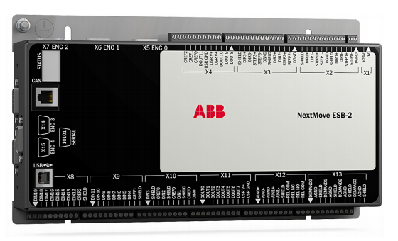
NextMove ESB-2 features
NextMove ESB-2 is a high performance multi-axis intelligent controller for servo and stepper
motors.
NextMove ESB-2 features the Mint motion control language. Mint is a structured form of
Basic, custom designed for stepper or servo motion control applications. It allows you to get
started very quickly with simple motion control programs. In addition, Mint includes a wide
range of powerful commands for complex applications.
Standard features include:
Control of 4 stepper axes and either 3 or 4 servo axes (model dependent).
Additional encoder input for master follower applications.
A wide variety of motion types including point to point moves, software cams and
gearing.
20 general purpose digital inputs, software configurable as level or edge triggered.
12 general purpose digital outputs.
2 differential analog inputs with 12-bit resolution.
4 single-ended analog outputs with 12-bit resolution.
USB 1.1 serial port (compatible with USB 2.0 and USB 3.0).
CANopen protocol for communication with Mint controllers and other third party
CANopen devices.
Programmable in Mint.
Drop-in replacement for NextMove ESB
This manual is intended to guide you through the installation of NextMove ESB-2.
The chapters should be read in sequence.
The Basic Installation section describes the mechanical installation of the NextMove ESB-2.
The following sections require knowledge of the low level input/output requirements of the
installation and an understanding of computer software installation. If you are not qualified in
these areas you should seek assistance before proceeding.
Note: You can check that you have the latest firmware and Mint WorkBench releases
by visiting the website www.abbmotion.com
Receiving and inspection
When you receive your NextMove ESB-2, there are several things you should do
immediately:
1. Check the condition of the shipping container and report any damage immediately to the
carrier that delivered your NextMove ESB-2.
2. Remove the NextMove ESB-2 from the shipping container and remove all packing
material. The container and packing materials may be retained for future shipment.
3. Verify that the catalog number of the NextMove ESB-2 you received is the same as the
catalog number listed on your purchase order. The catalog number is described in the
next section.
4. Inspect the NextMove ESB-2 for external damage during shipment and report any
damage to the carrier that delivered your NextMove ESB-2.
5. If NextMove ESB-2 is to be stored for several weeks before use, be sure that it is stored
in a location that conforms to the storage humidity and temperature specifications shown
in section 7.1.11.
2.2.1 Identifying the catalog number
Different models of NextMove ESB-2 are available. As a reminder of which product has been
installed, it is a good idea to write the catalog number in the space provided below.
A description of the catalog numbers are show in the following table:
Catalog
number
Description Serial
port
Stepper
output
type
NSB202-501 3 servo axes, 4 stepper axes, 2 extra encoder inputs RS232 Differential
NSB202-502 3 servo axes, 4 stepper axes, 2 extra encoder inputs RS485
NSB203-501 3 servo axes, 4 stepper axes, 2 extra encoder inputs RS232 Open
collector NSB203-502 3 servo axes, 4 stepper axes, 2 extra encoder inputs RS485
NSB204-501 4 servo axes, 4 stepper axes, 1 extra encoder input RS232 Differential
NSB204-502 4 servo axes, 4 stepper axes, 1 extra encoder input RS485
NSB205-501 4 servo axes, 4 stepper axes, 1 extra encoder input RS232 Open
collector NSB205-502 4 servo axes, 4 stepper axes, 1 extra encoder input RS485
Introduction
You should read all the sections in Basic Installation to ensure safe installation.
It is important that the correct steps are followed when installing the NextMove ESB-2. This
section describes the mechanical installation of the NextMove ESB-2.
3.1.1 Location requirements
You must read and understand this section before beginning the installation.
To prevent equipment damage, be certain that input and output signals are
powered and referenced correctly.
To ensure reliable performance of this equipment be certain that all signals to/
from the NextMove ESB-2 are shielded correctly.
Avoid locating the NextMove ESB-2 immediately above or beside heat
generating equipment, or directly below water steam pipes.
Avoid locating the NextMove ESB-2 in the vicinity of corrosive substances or
vapors, metal particles and dust.
The safe operation of this equipment depends upon its use in the appropriate environment.
The following points must be considered:
The NextMove ESB-2 is designed to be mounted indoors, permanently fixed and
located.
The NextMove ESB-2 must be secured by the slots in the metal case.
The NextMove ESB-2 must be installed in an ambient temperature of 0 °C to 45 °C
(32 °F to 113 °F).
The NextMove ESB-2 must be installed in relative humidity levels of less than 80% for
temperatures up to 31 °C (87 °F) decreasing linearly to 50% relative humidity at 45 °C
(113 °F), non-condensing.
The NextMove ESB-2 must be installed where the pollution degree according to IEC
60664-1 shall not exceed 2.
There shall not be abnormal levels of nuclear radiation or X-rays.
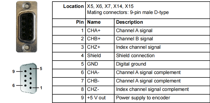
Five incremental encoders may be connected to NextMove ESB-2, each with
complementary A, B and Z channel inputs. Each input channel uses a MAX3095 differential
line receiver with pull up resistors and terminators. Encoders must provide RS422 differential
signals. The use of individually shielded twisted pair cable is recommended. A 5 V (±5%),
250 mA supply is provided on each connector for powering the encoder. The same 5 V
supply is also present on connectors X2 and X3 for powering external circuits (see sections
4.4.1 and 4.4.2). Ensure that the total combined current demand of all 5 V outputs does not
exceed 1.85 A.
Encoder inputs ENC 0 - ENC 3 can be read and controlled with a range of Mint keywords
beginning with ENCODER... . When using these keywords, the encoder’s number is used
as the channel parameter. For example, Print ENCODER(2) reads the ENC 2 input.
Encoder input ENC 4 can be read and controlled with a range of Mint keywords
beginning with AUXENCODER... . When its position has been latched by a fast interrupt
(see section 4.3.1.1) it can also be controlled using Mint keywords beginning with
FASTAUX... . When using the AUXENCODER... or FASTAUX... keywords, the channel
parameter 1 is used (i.e. auxiliary encoder channel 1). For example,
Print FASTAUXENCODER(1) reads the latched value read from ENC 4. Note that
auxiliary encoder channel 0 is used to reference the auxiliary encoder input formed by
digital inputs DIN17 - DIN19 (see section 4.3.1.4).
Figure 20: Encoder inputs - keyword and channel summary
Location X5, X6, X7, X14, X15
Mating connectors: 9-pin male D-type
Pin Name Description
1 CHA+ Channel A signal
2 CHB+ Channel B signal
3 CHZ+ Index channel signal
4 Shield Shield connection
5 GND Digital ground
6 CHA- Channel A signal complement
7 CHB- Channel A signal complement
8 CHZ- Index channel signal complement
9 +5 V out Power supply to encoder
1
9 5
6
ENC 0
ENC 1
ENC 2
ENC 3
DIN17
DIN18
DIN19
ENC 4 Print ENCODER(0)
Print ENCODER(1)
Print ENCODER(2)
Print ENCODER(3)
Print AUXENCODER(1)
Print FASTAUXENCODER(1)
Print AUXENCODER(0)
- YOKOGAWA
- Reliance
- ADVANCED
- SEW
- ProSoft
- WATLOW
- Kongsberg
- FANUC
- VSD
- DCS
- PLC
- man-machine
- Covid-19
- Energy and Gender
- Energy Access
- Renewable Integration
- Energy Subsidies
- Energy and Water
- Net zero emission
- Energy Security
- Critical Minerals
- A-B
- petroleum
- Mine scale
- Sewage treatment
- cement
- architecture
- Industrial information
- New energy
- Automobile market
- electricity
- Construction site
- HIMA
- ABB
- Rockwell
- Schneider Modicon
- Siemens
- xYCOM
- Yaskawa
- Woodward
- BOSCH Rexroth
- MOOG
- General Electric
- American NI
- Rolls-Royce
- CTI
- Honeywell
- EMERSON
- MAN
- GE
- TRICONEX
- Control Wave
- ALSTOM
- AMAT
- STUDER
- KONGSBERG
- MOTOROLA
- DANAHER MOTION
- Bentley
- Galil
- EATON
- MOLEX
- Triconex
- DEIF
- B&W
- ZYGO
- Aerotech
- DANFOSS
- KOLLMORGEN
- Beijer
- Endress+Hauser
- schneider
- Foxboro
- KB
- REXROTH
- YAMAHA
- Johnson
- Westinghouse
- WAGO
- TOSHIBA
- TEKTRONIX
- BENDER
- BMCM
- SMC
- HITACHI
- HIRSCHMANN
- XP POWER
- Baldor
- Meggitt
- SHINKAWA
- Other Brands
- UniOP
- KUKA
- IBA
- Beckhoff
- ADLINK
51
-
Beckhoff CP6500-1012-0060 - Control Cabinet PC Interface Unit
-
Beckhoff FC5202-0000 - 2-Channel DeviceNet Master PCI Interface Card
-
Beckhoff CP6606-0001-0020 - 7-Inch Economy Panel PC Touch
-
Beckhoff CP2921-0010 - Multi-Touch Integrated Control Panel Display
-
Beckhoff CP7802-0001-0010 - 15-Inch Touch Screen Control Panel HMI
-
Beckhoff C6920-0050 - Control Cabinet Industrial PC
-
Beckhoff BK9105 - EtherNet/IP Bus Coupler Network Interface
-
Beckhoff 31 Modules - Bus Terminal Slice I/O Lot Assortment
-
Beckhoff CX2020-0120 - Embedded PC Basic CPU Module 8GB CFast Card
-
Beckhoff CP7001-0000 - HMI Control Panel Touch Screen
-
B&R 7EX484.50-1 - System 2005 Controller Base Module Slots
-
Beckhoff EK1322 - 2-Port EtherCAT P Extension Feed-In Terminal
-
Beckhoff CP6606-0001-0020 - 7-Inch Single-Touch Economy Panel PC
-
Beckhoff CP6607-0001-0000 - Economy Installation Operator Panel PC 5.7-Inch
-
Beckhoff AX5103-0000-0200 - Digital Compact Servo Driver 3 Phase
-
Beckhoff CP7802-0001-0010 - 15-Inch Touch Screen Control Panel
-
Beckhoff AX8620 - Power Supply Module Axis System
-
Beckhoff CX2030-0121 - Embedded PC Controller Module
-
Beckhoff CP6606-0001-0020 - 7-Inch Economy Panel PC Touch Screen
-
Beckhoff CX2030-0121 - Embedded PC CPU Module Windows Standard 7
-
Beckhoff BX3100-0000 - PROFIBUS DP Bus Terminal Controller
-
Beckhoff CX1020-0000 - Controller Set with Power Supply Unit
-
Beckhoff EK1100 - EtherCAT Coupler Terminal Module Set
-
Beckhoff CP7002-1043-0010 - HMI Display Panel with Control Panel Bracket
-
Beckhoff AM8031-0D10-0000 - Synchronous Servo Motor
-
Beckhoff CX5130-0175 - Embedded PC 4GB RAM Controller
-
Beckhoff CX5130-0155 - Embedded PC Automation Controller
-
Beckhoff C6930-0010 - Control Cabinet Industrial PC Core Duo
-
Beckhoff CP3924-0000 - Multi-Touch Control Panel Display
-
Beckhoff AM8023-0F20-0000 - Synchronous Servo Motor
-
B&R KL3362 - Bus Terminal Thermocouple Input Module
-
Beckhoff AL2006-0000-0000 - Linear Servo Motor Three Phase
-
Beckhoff CX5140-0155 - Embedded PC CPU Controller Module
-
Beckhoff FC9002 - Ethernet PCI Network Interface Card
-
Beckhoff CP7203-0021-0040 - Built-In Panel PC 19-Inch Touch Screen
-
Beckhoff C6930-0020 - Control Cabinet Industrial PC HDD CF Card
-
Beckhoff CX2900-0033 - Memory Card CFast Storage
-
Beckhoff CP6201-0001-0020 - Built-In Panel PC Display
-
b+m surface systems C6930-1121-0060 - Industrial PC Beckhoff Core i7
-
Beckhoff CP2221-0010 - Multi-Touch Built-In Panel PC
-
Beckhoff C6017-0010 - Ultra-Compact Industrial PC
-
Beckhoff FC5102-0000 - 2-Channel CANopen PCI Interface Card
-
Beckhoff CP7021-0000-0000 - HMI Control Panel Interface
-
Beckhoff CP2216-0020 - Multi-Touch Built-In Panel PC
-
Beckhoff C6140 - Industrial PC Tower System Pentium 4
-
Beckhoff AM3033-1E40 - Servo Motor with Gearbox Assembly
-
Beckhoff CX9020-0115 - Embedded PC CPU Controller Module
-
Beckhoff CP6809-0001-0000 - Built-In Control Panel HMI Terminal
-
Beckhoff CP3919-0000 - Multi-Touch Control Panel Touchscreen Monitor
-
Beckhoff AM8053-0LHB-0000 - Synchronous Servo Motor
-
Beckhoff C6920-1028-0000 - Control Cabinet Industrial Computer PC
-
Beckhoff CX1100-0014 - Power Supply Unit for CX1030
-
Beckhoff CX9001-0101 - Embedded PC CPU Controller Module
-
Beckhoff CP3916-1428-0000 - Control Panel Multi-Touch Monitor
-
Beckhoff CP7037-1027-0010 - HMI Built-In Control Panel PC
-
Beckhoff CX1020-0120 - CPU Module DVI USB Windows Standard
-
Beckhoff CX5020-0121 - Embedded PC Controller Module
-
Beckhoff EL5042 - 2-Channel Encoder Interface BiSS C EtherCAT Terminal
-
Beckhoff CP7201-0021-0040 - Built-In Panel PC Touch Monitor
-
B&R X20-RT-8401 - reACTION Technology Module I/O Block
-
Beckhoff CP2915-0010 - HMI Control Panel Display Touch Screen
-
Beckhoff EL7221 - Servomotor Cyber Terminal EtherCAT Module
-
Beckhoff CX5140-0175 - Embedded PC CPU Module
-
Beckhoff C6017-0010 - Ultra-Compact Industrial PC
-
Beckhoff CX2020-0130 - Embedded PC Basic CPU Module
-
Beckhoff CX1030-0011 - Basic CPU Module Windows CE 6.0
-
Beckhoff AM8043-1E00-0000 - Synchronous Servo Motor
-
Beckhoff CX1020-0110 - CPU Module Controller Interface Bundle
-
Beckhoff C6930-1069-0030 - Control Cabinet Industrial PC Mainboard CB3054-0001
-
Beckhoff KL9528 - Power Supply Terminal Module
-
Beckhoff AM8053-0K20-0000 - Synchronous Servo Motor
-
Beckhoff CX5020-1111 - Embedded PC Controller Module
-
Beckhoff CX5130-0175 - Embedded PC CPU Module Intel Atom
-
Beckhoff CP6401-1024-0040 - Husky Display Control Panel HMI Terminal
-
Beckhoff CP2616-0000 - Multi-Touch Display Automation Panel PC
-
Beckhoff CP7921-1075-0000 - 12-Inch HMI Control Panel ELO Touch
-
Beckhoff C6930-0060 - Control Cabinet Industrial PC SSD
-
Beckhoff AX5112-0000 - Digital Compact Servo Drive 3 Phase
-
Beckhoff C6930-0040 - Control Cabinet Industrial PC Intel Core i5
-
Beckhoff CP2616-0000 - Multi-Touch Display Automation Panel PC
-
Beckhoff KL1414 - 4-Channel Digital Input Bus Terminal
-
Beckhoff CX1020-0000 - Basic CPU Module Controller
-
Beckhoff CP6201-1008-0000 - 12-Inch Built-In Panel PC
-
Beckhoff CP7021-0000 - HMI Control Panel Display Screen
-
Beckhoff AX5106-0000 - Digital Compact Servo Drive
-
Beckhoff BX3100-0000 - Profibus DP Bus Terminal Controller
-
Beckhoff CP2916-0000 - Multi-Touch Built-In Control Panel
-
Beckhoff C6925-0030 - Fanless Control Cabinet Industrial PC
-
Beckhoff C6330 - Industrial PC Motherboard Boser HS6237 Celeron
-
Beckhoff AM3033-0C00-0000 - Synchronous Servo Motor
-
Beckhoff EL6080 - EtherCAT Memory Terminal Module
-
Beckhoff CX2100-0014 - Power Supply Unit Module
-
Beckhoff CP6907-1000-000 - Economy Built-In Control Panel HMI
-
Bosch CP2715-1014-0010 - Panel PC Touch Screen Monitor
-
Beckhoff C6920-0050 - Control Cabinet Industrial PC
-
Beckhoff CP2712-1002-0000 - Baumann Automation Touch Control Panel PC
-
Beckhoff CX1001-0111 - Embedded PC CPU Power Supply Fieldbus Module Assembly
-
Beckhoff AM8061-0JH1-0000 - Synchronous Servo Motor
-
Nexcom EBS1575P - System Module Beckhoff Fieldbus Interface FC3101
-
Beckhoff CU8860-1000 - USB Extended Receiver Module
-
Beckhoff C9620-1080-0040 - Control Cabinet Industrial PC
-
Beckhoff C6640-0000 - Control Cabinet Industrial PC
-
Beckhoff C6525-0030 - Fanless Built-In Industrial PC
-
Beckhoff CX2030-0121 - Embedded PC CPU Module TwinCAT 2
-
Beckhoff CX5130-0155 - Embedded PC CPU Module
-
Beckhoff CX1020-0000 - Controller Set Module Combination Set
-
Beckhoff CU2005 - Industrial Ethernet Switch Module
-
Beckhoff ELM9410-0000 - Power Supply Terminal EtherCAT
-
Beckhoff AM8023-0EH1-0000 - Synchronous Servo Motor
-
Beckhoff CX5020-0112 - Embedded PC CF Memory Card
-
Beckhoff CP3921-0010 - Control Panel Multi-Touch Screen
-
Beckhoff CP7232-1000-0000 - Industrial Panel PC Touch Screen
-
Beckhoff C6525-1022-0005 - Fanless Built-In Industrial PC
-
Beckhoff AM3052-0K41-1001 - Synchronous Servo Motor
-
Beckhoff CP2921-0010 - Multi-Touch Built-In Control Panel
-
Beckhoff c6017-0010 - Ultra-Compact Industrial PC
-
Beckhoff AX5106-0000-0200 - Servo Drive Intelligent Drive Module
-
Beckhoff BK7200 - Fipio Bus Coupler PLC Module
-
Beckhoff EP-M845B - Industrial Mainboard Motherboard Rev 2.1
-
Beckhoff CX5020-0111 - Embedded PC CPU Module
-
Beckhoff CP6802-0001-0010 - Built-In HMI Control Panel
-
Beckhoff CX2100-0004 - Power Supply Unit Module
-
Beckhoff C6320 - Control Cabinet Industrial PC
-
Beckhoff C6525-0030 - Fanless Built-In Industrial PC Celeron
-
Beckhoff CX1010-0112 - Embedded PC Controller Module
-
Beckhoff EPP6002-0002 - EtherCAT Box Serial Interface
-
Beckhoff CP7721-1084-0020 - Touch Panel PC Trumpf Laser Screen
-
Beckhoff C6140 - Industrial PC Mainboard Tower Computer

K-JIANG

Add: Jimei North Road, Jimei District, Xiamen, Fujian, China
Tell:+86-15305925923