
K-WANG


Woodward ESDR4 Current Differential Protection Relay
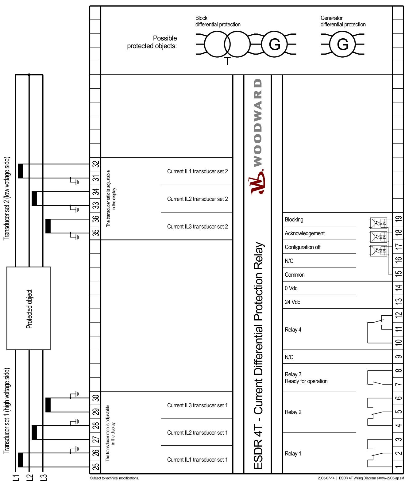
Woodward ESDR4 Current Differential Protection Relay
Safety precautions
Warning: Before operation, read the complete manual and relevant publications, and follow the factory and safety instructions. If the equipment is modified or used beyond the specified operating limits without authorization, it may cause personal injury and property damage, and may void the warranty and certification. The prime mover should be equipped with an independent overspeed shutdown device.
Attention: Before disconnecting the battery, turn off the charging device. When handling electronic controls, release static electricity from the body and avoid contact with materials that are prone to static electricity, such as plastics. Do not touch printed circuit board components or conductors.
Relay Overview
Function: ESDR 4T is a three-phase current differential protection relay used for generators, motors, and transformers. By measuring the current on both sides of the protected object, it detects short circuits and ground faults within the protection zone, and does not operate for faults outside the zone, ensuring selective protection.
Working principle: Electrical isolation is applied to 6 measured currents, and differential current and braking current of each phase are calculated separately. When calculating, parameters such as transformer vector group, rated current, current transformer ratio, and voltage ratio are considered.
Model composition: It consists of a basic unit and various options, such as ESDR 4T01B representing a standard unit, no voltage measurement, CT input of 1A, and front board installation.
ESD protection
When handling electronic equipment, it is necessary to touch grounded metal objects to discharge static electricity, wear cotton clothes, and keep away from plastic, vinyl and foam materials.
When disassembling the printed circuit board, ensure that the device is completely powered off and only touch the edges. The new board should be stored in an anti-static bag.
Wiring (wiring)
Power supply: 24Vdc (± 25%), terminal 13 is+24V, 14 is 0V reference voltage, maximum current is 2.5mm ².
Measurement input: 6 current measurement inputs, using current transformers, the secondary side needs to be grounded, the polarity needs to be correct, terminals 25-36 are used to connect CT inputs, and the maximum current is 4mm ².
Discrete input: Terminals 17-19 are configured as off, confirm, and block inputs, with input voltages ranging from 18-250V (ac/dc) and a maximum current of 2.5mm ².
Relay output: 4 relay outputs, with configurable functions for relays 1-2, ready for operation for relay 3, warning for relay 4, maximum contact capacity of 250Vac, and maximum current of 2.5mm ².
Function Description
Differential current monitoring: divided into two levels. The first level is a warning, which can be enabled or disabled. When the warning characteristic is exceeded, text will be displayed and relay contacts will be activated; The second level is tripping, which can monitor adjustable tripping characteristics and a fixed tripping threshold relative to 100% of the rated current of the generator. The tripping characteristics have a 2% hysteresis.
Trip characteristics: According to the braking current, it is divided into three sections. The trip threshold is independent of the braking current from 0 to X12, increases with the increase of braking current from X12 to 5 × IN, and remains constant at 85% when it exceeds 5 × IN.
Electrical suppression of surge and overexcitation: using digital Fourier transform to detect second and fifth harmonics, enabling the "Stabilization Rush" function and setting the action margin to prevent false tripping.
Self monitoring: Provides a ready to operate signal through contact components, and the signal is disabled when the power supply voltage is below approximately 19Vdc or there is an internal fault.
Display and operation components
LED: including brake current, differential current, monitoring on and alarm LED, displaying the current status.
Button: There are message scrolling, selection, display scrolling, number increase, clear, and cursor movement buttons that can switch between display mode and configuration mode.
LC display screen: Two lines of 16 characters, displaying measurement values, alarm messages, and configuration parameters, with adjustable contrast.
configuration
Basic data: Language can be selected, software version can be viewed, configuration parameters need to be performed in configuration mode, and if there is no operation for 60 seconds, it will automatically return to display mode.
Configuration access: The sealing function can be enabled to protect the configuration through a five digit code, preventing unauthorized access and modification.
Relay configuration: The relay can be configured to operate in either working current or idle current mode, with parameters such as automatic confirmation, release delay, and message confirmation delay set, and warning messages assigned to the relay.
Rated data: Input the rated current of the protected object, the rated values of the high and low voltage side current transformers, and the voltage, and set the transformer vector group.
Differential protection configuration: After enabling differential protection, modify the triggering value, delay time, hysteresis of the trip characteristics, set parameters for surge and overexcitation suppression, and display harmonics.
debugging
Prerequisite: Connect the equipment according to the wiring diagram, connect a 24Vdc power supply, set parameters, and activate the display mode.
Secondary value testing: Using three-phase testing equipment to test the threshold, single phase testing systems may produce mismatched measurement values due to phase matching system elimination.
One time value debugging: Remove all testing equipment before testing to ensure that the current transformer is not open circuited, configure the system to allow for the most precise current regulation, test connection correctness, perform cyclic exchange testing, and retest after correct connection.
Appendix
Size: Display the external dimensions and installation hole positions of ESDR 4T.
Technical data: including technical parameters such as measured current, frequency, accuracy, power consumption, environmental conditions, digital inputs, relay outputs, protection functions, terminal and housing protection.
Parameter List: lists all parameters and their setting ranges and default values during the configuration process.
Service options: Provide product service options, including return for repair, packaging requirements, return authorization number, replacement parts, and ways to contact Woodward.
Characteristics of Protection Function
Differential current monitoring
Two level monitoring: the first level is a warning, which displays text and activates relay contacts when the threshold is exceeded; The second level is for tripping, which can monitor adjustable tripping characteristics (Id<IN) and a fixed threshold of 100% rated current (Id>IN), and the tripping delay can be independently set.
Has a 2% hysteresis characteristic to prevent frequent signal movements near the threshold.
Selective protection
It only operates when there is a fault within the protection zone, and does not trigger faults outside the zone. Accurate protection is achieved by measuring the current difference on both sides.
Surge and overexcitation suppression
Using digital Fourier transform (DFT) to detect 2nd (surge) and 5th (overexcitation) harmonics, enabling electrical suppression function can prevent false tripping, and action margin (10% -50%) needs to be set.
Technical parameter characteristics
Measurement and Accuracy
Supports 6 current inputs, measurement frequency 40-70Hz, accuracy Class 1, linear measurement range up to 5 × I N.
The secondary side of the current transformer supports 1A or 5A, with a rated short-time current (1s) of 100 × I N (1A) or 30 × I N (5A).
Power supply and power consumption
The power supply is 24Vdc (± 25%), with a maximum inherent power consumption of 6W, and supports wide temperature operation (operating temperature -20~70 ℃).
Output capability
4 relay outputs, contact material AgCdO, supporting resistive and inductive loads:
Resistive load: 2A@250Vac The 2A@24Vdc Wait.
Sensory load: 1A@250Vac The 0.36A@125Vdc Wait.
Configuration and operational characteristics
Flexible parameter settings
Configurable transformer vector group (such as Yd5, Dd0, etc.), rated current, CT ratio, voltage ratio and other parameters to adapt to different devices.
The tripping characteristic curve can be adjusted, including the braking current threshold (X12), differential current threshold (Y1/Y2), and delay time.
Human Computer Interaction and Display
The front panel is equipped with an LC display screen (two lines of 16 characters) and LED indicator lights (brake current, differential current, monitoring status, alarm), which display real-time measurement values and fault information.
Support switching between display mode and configuration mode through buttons (message scrolling, selection, numerical adjustment, etc.), easy to operate.
Relay function can be customized
Relays 1-2 and 4 can be configured for operating current (N.O.) or idle current (N.C.) mode, while relay 3 is fixed as a "ready to run" signal and supports automatic/manual fault confirmation.
Safety and protection features
electrostatic protection
Electronic components are sensitive to static electricity, and during operation, body static electricity must be released to avoid contact with plastic and other materials. Disassembling circuit boards must follow anti-static regulations.
Electrical safety design
Measure input electrical isolation to prevent interference; The power supply and input/output terminals support overload protection, and the terminal wiring specifications are clear (2.5mm ² or 4mm ²).
Sealing and Certification
The protection level of the front panel is IP42 (standard) or IP54 (with gasket), and the rear is IP21. It has passed CE and UL certification and is suitable for ordinary places and ship environments (GL certification).
Application scenario characteristics
Applicable object: Designed specifically for block connections of generators, motors, and transformers, forming protection zone boundaries and accurately detecting faults within the zone.
Compatibility: Supports different transformer vector groups and ratios, adapts to high/low voltage side systems through parameter configuration, and meets the requirements of complex power systems.
summarize
The ESDR 4T relay, with differential protection as its core, combines high-precision measurement, flexible configuration, anti-interference capability, and safety protection design. It is suitable for fault protection of key equipment in industrial power systems, ensuring stable system operation.
- YOKOGAWA
- Reliance
- ADVANCED
- SEW
- ProSoft
- WATLOW
- Kongsberg
- FANUC
- VSD
- DCS
- PLC
- man-machine
- Covid-19
- Energy and Gender
- Energy Access
- Renewable Integration
- Energy Subsidies
- Energy and Water
- Net zero emission
- Energy Security
- Critical Minerals
- A-B
- petroleum
- Mine scale
- Sewage treatment
- cement
- architecture
- Industrial information
- New energy
- Automobile market
- electricity
- Construction site
- HIMA
- ABB
- Rockwell
- Schneider Modicon
- Siemens
- xYCOM
- Yaskawa
- Woodward
- BOSCH Rexroth
- MOOG
- General Electric
- American NI
- Rolls-Royce
- CTI
- Honeywell
- EMERSON
- MAN
- GE
- TRICONEX
- Control Wave
- ALSTOM
- AMAT
- STUDER
- KONGSBERG
- MOTOROLA
- DANAHER MOTION
- Bentley
- Galil
- EATON
- MOLEX
- Triconex
- DEIF
- B&W
- ZYGO
- Aerotech
- DANFOSS
- KOLLMORGEN
- Beijer
- Endress+Hauser
- schneider
- Foxboro
- KB
- REXROTH
- YAMAHA
- Johnson
- Westinghouse
- WAGO
- TOSHIBA
- TEKTRONIX
- BENDER
- BMCM
- SMC
- HITACHI
- HIRSCHMANN
- XP POWER
- Baldor
- Meggitt
- SHINKAWA
- Other Brands
- UniOP
- KUKA
- IBA
- Beckhoff
-
ADLINK PCI-7433 - switch value acquisition card Isolated Digital Input Card
-
ADLINK PCI-9112 - 51-12252-0D20 Multi-Function Data Acquisition Card
-
ADLINK NUPRO-A301 REV:1.4 - industrial control motherboard PICMG Full-Size SBC
-
ADLINK 51-18502-0A10 - Frame Grabber Image Acquisition Interface Card
-
ADLINK PCI-7296 - 51-12009-0A50 PCB-I-E-925=6DX1 96-CH Parallel Digital I/O Board
-
ADLINK PCI-8132 GP A2 - Motion Control Card 2-Axis Servo & Stepper Controller
-
ADLINK PCI-7442 - switch quantity card data acquisition card 64-CH Isolated Card
-
ADLINK HPX-13S4 - baseboard PICMG 1.3 Passive Backplane Chassis Baseplate
-
ADLINK NuPRO-590 / NTC-567-ZM-F36 - Single Board Computer PCB-I-E-1853=9L21 Half-Size SBC
-
ADLINK PCIe-8332 - 16-axis plate Motion Control Hardware Card
-
ADLINK NuPRO-775 REV.B1 - motherboard Pentium 4 Full-Size PICMG SBC
-
ADLINK PXI-3920 - Embedded Controller 3U PXI cPCI System Intelligence Board
-
ADLINK PCI-8134 - driver card motion control card 4-Axis Controller Board
-
ADLINK HSL-DI32-M-N-011 / HSL-TB32-M-DIN - Digital Input & Base Module PLC Distributed I/O System
-
ADLINK PCI-6216V-206 / PCI-208V 009 - 16 CH 16bit analog output card
-
ADLINK NuPro-E330 - 51-41805-0A20 PCB Single Board Computer Host Board
-
ADLINK PCI-1622C - Card 8-Port RS-232/422/485 PCI Serial Communication Board
-
ADLINK PCIe-7432 - 51-18402-0A10 Carte PCIe Avec Plage D'Entrée Élevée Isolated DIO Card
-
ADLINK PCI-7250 - PCI Acquisition Card 8-CH Relay Output Isolated DI Card
-
ADLINK PCI-7230 - 32-CH Isolated Digital I/O Card
-
ADLINK PCI-8164 - PCB 4-Axis Motion Controller Card
-
ADLINK PCI-7854 - Collection card High-Speed Link Distributed Motion Controller
-
ADLINK NuPRO-935A/LV - industrial control computer motherboard Full-Size PICMG SBC
-
ADLINK IMB-M40H - motherboard IH61-AA4 1155 LGA1155 Micro-ATX Mainboard
-
ADLINK PCI-7248 - Linhua 51-12006-0A40 48-CH Parallel Digital I/O Card
-
ADLINK HPCI-14S12U - Linhua industrial computer baseboard Passive Backplane
-
ADLINK PCI-8132 Rev.A2 - 2-Axis Servo & Stepper Motion Controller Card
-
ADLINK ACL-8111 - ISA card Multi-Function DAQ Card
-
ADLINK ACL-8111 - ISA card Multi-Function Data Acquisition Board
-
ADLINK PCI-7200 REV.A3 - Digital I/O card 12MB/s High-Speed Parallel Digital I/O
-
ADLINK PCI-7296 REV.A3 - 96-CH High-Density Opto-Isolated DIO Card
-
ADLINK PCI-7434 - 64-CH Isolated Digital Output Card
-
ADLINK M-342 - atx motherboard Industrial PC Mainboard
-
ADLINK NuPRO-935ADV (A) 1.9 - CPU Board Intel Core 2 Quad CPU Q9500 2.83GHz PICMG Board
-
ADLINK NUPRO-935A/DV - motherboard dual network port 51-41802-0A10 CPU Board
-
ADLINK PCI-RTV24 - image capture card Analog Video Frame Grabber Board
-
ADLINK HPX-13S4 - device baseboard PICMG 1.3 Passive Backplane Chassis Baseplate
-
ADLINK PCI-8134A - control card 4-Axis Motion Controller Card
-
ADLINK ACL-7130 REV. B2 - industrial control capture card Isolated Digital I/O Board
-
ADLINK EBP-13E2 - Industrial Backplane Board Passive Backplane Baseboard
-
ADLINK NuPRO-935ADV (A) 1.9 - CPU Board Intel Core 2 Quad CPU Q9500 2.83GHz PICMG SBC
-
ADLINK PCI-8134A - motion control card 4-Axis Pulse-Train Controller Card
-
ADLINK PCI-9112 REV A.1 - Multi Function DA&C Board Data Acquisition Card
-
ADLINK 51-12001-0C20 - Circuit Board Multi-Function Data Acquisition Hardware
-
ADLINK PCI-7300A - 80-CH High-Speed Digital I/O Card
-
ADLINK PCI-7230 - 16-CH Isolated Digital Input Output Card
-
ADLINK DIN-814-GP - motion control module Interface Terminal Block
-
ADLINK NUPRO-A40H - 51-41807-1A20 Industrial Control Motherboard LGA1155
-
ADLINK PCI-7433 rev A2 - Isolated Digital Input Card
-
ADLINK NuPRO-780 - Pentium III 800 512 MB SBC NuPRO780 51-41309-0B2 Single Board Computer
-
ADLINK PCI-7853 / PCI-7854 - Acquisition card High-Speed Link Control Card
-
ADLINK NUPRO-852 / NUPRO-852LV - Industrial motherboard Full-Size PICMG CPU Board
-
ADLINK NuPRO-842LV/P - 51-41360-0B30 Industrial Motherboard Half-Size PICMG SBC
-
ADLINK PCI-FIW64 - 4/2 Channel IEEE1394B Image Capture Card Frame Grabber
-
ADLINK PCI-7851 Rev A1.1 - HSL system card High-Speed Link Master Controller
-
ADLINK PCI-7230 - 51-12003-0A50 card 32-CH Isolated Digital I/O Card
-
ADLINK NuPRO-841REV:1.0 - Industrial CPU Board Mainboard
-
ADLINK NuPRO-841 REV:1.0 - motherboard Industrial Control PC Mainboard
-
ADLINK PCI-8256 - 8-Axis Advanced Motion Control PCI Board
-
ADLINK PCI-6S / PCI6S - Backplane 6-Slot Passive Backplane Board
-
ADLINK PCI-7234 REV B3 - 32-CH Isolated Digital Output PCI Card
-
ADLINK PCI-8213 - HannStar MV-4 51-45003-0b4 Board
-
ADLINK PCI-7233 - 51-12004-0a20 board PCI7233 32-CH Isolated Digital Input Card
-
ADLINK PCI-7851 - 006 51-24003-0B20 High-Speed Link Master Motion Control Card
-
ADLINK PCI-7432 - 64-CH Isolated Digital I/O PCI Cards
-
ADLINK LPCI-3488 - Card Low Profile IEEE-488 GPIB Interface Card
-
ADLINK HPCI14S REV.B1 - industrial control computer base plate Passive Backplane
-
ADLINK NEON-1020 - Industrial camera Smart Camera Vision System
-
ADLINK PCI-7432 - Isolated Digital I/O PCI Card 64-CH
-
ADLINK Pcm-7250+ - 8-Ch Relay Outputs & 8-Ch Isolated DI Module PC/104
-
ADLINK CPCI-7841 - DUAL-PORT ISOLATED CAN INTERFACE CARD CompactPCI
-
ADLINK PCI-3488 / PCI-GPIB - PCI IEEE-488 GPIB Interface Card
-
ADLINK PCI-1711U - Card Multi-Function Data Acquisition Board
-
ADLINK NUPRO-A301 - REV:1.1 1.2 1.4 PICMG Full-Size Single Board Computer
-
Adlink DIN-50S-01 - PLOTECH 51-14024-0A40 50-pin Wiring Terminal Board
-
Chroma 52962 / 58183 - PXI Optical Spectrometer carrier adapter Card
-
ADLINK PCI-6208V - PCI DATA ACQUISITION & RECORDING CARD 8-CH Analog Output
-
ADLINK HSL-DI32-DB-N - Industrial Control Board Distributed Digital Input Module
-
ADLINK HSL-AO4-U - 4-CH HIGH SPEED LINK ANALOG OUTPUT MODULE Distributed I/O
-
ADLINK PCI-7396 - 0050 GP 51-12012-0B20 96-CH High-Speed Digital I/O Card
-
ADLINK NUPRO-935A/DV - 51-41802-0A10 motherboard Industrial CPU Single Board Computer
-
ADLINK PCI-9111 DG - Industrial Acquisition Card Multi-Function DAQ Card
-
ADLINK NuPRO-E315 - industrial computer motherboard Intel Atom SHB SBC
-
ADLINK NUPRO-406 REV:B1 - Industrial Control Motherboard Full-Size PICMG CPU Board
-
ADLINK NuPRO-E330 - motherboard Industrial Control System Host Board PICMG 1.3
-
ADLINK ACL-6128A 103 - 51-11002-1A4 2-CH Isolated Analog Output Card
-
XTRAMUS cPS-H325/AC - POWER SUPPLY NUSTREAMS 600 NETWORK TESTING EQUIPMENT Power Module
-
ADLINK DIN-814P-A4 - 51-14056-0A10 Terminal Block Motion Control Breakout Board
-
ADLINK TB-24P/24-01 - 24-Channel Card Terminal Breakout Board
-
ADLINK PCI-7251 - 51-12008-0A30 PCI7251 8-CH Relay Output Isolated Digital Input Card
-
ADLINK HSL-TB64-DIN REV A1 / HSL-DO32-DB-N - 2ea Board Breakout Terminal Board Distributed I/O Module
-
ADLINK NuPRO-865 REV 3.0 - industrial computer motherboard Full-Size PICMG SBC
-
ADLINK NUPRO-A40H - motherboard 51-41807-1A30 OSP H61 Industrial PC Mainboard
-
ADLINK LPCI-3488A - PCI Card 51-12801-0A30 GPIB Interface Card
-
ADLINK DIN-825-4P0 - 51-14085-0A30 Terminal Printed Circuit Board Breakout Block
-
ADLINK IMB-T10/D2550 V - MOTHER BOARD 80-PXG160-A1A01 IMB-T10-M2G-S32G Industrial Mainboard
-
ADLINK PCI-8144N - Motion Control card Stepper Motor Controller
-
ADLINK PCI-7433 - Digital acquisition card Isolated Digital Input Card
-
ADLINK PCI-9112 DG - Data Acquisition card 51-12252-0D20 Multi-Function DAQ
-
ADLINK IMB-M40H - motherboard IH61-AA4 1155 LGA1155 Micro-ATX Mainboard
-
ADLINK TB-24P/24-01 - Carte 24 voies Terminal Breakout Board Connector Module
-
ADLINK HSL-D16DO16-M-NN - Distributed Discrete Input Output I/O Module
-
ADLINK PCI-7248 - PCI CARD 51-12006-0A40 48-CH Parallel Digital I/O Board
-
ADLINK HSL-DI32-DB-N - Industrial Control Board Distributed I/O Digital Input Module
-
ADLINK PCI-7433 - Pci 7433 Isolated Digital Input Card
-
ADLINK PCI-6208V - 008 Data acquisition card 8-CH Analog Output Card
-
ADLINK IH61-AA4 - industrial motherboard LGA1155 Micro-ATX Mainboard
-
ADLINK PXI-3920 - PXI 3U cPCI Industrial Controller Embedded System CPU Board
-
ADLINK PCI-6308 - Analog Output DAQ Card Isolated Voltage Output Card
-
ADLINK PCI-7200 - data acquisition card REV.A3 High-Speed Parallel DIO Card
-
ADLINK NuPRO-E315 - Industrial Control Computer Motherboard PICMG 1.3 SHB SBC
-
ADLINK PCI-1610C - Card 4-Port Isolated RS-232 PCI Serial Communication Card
-
ADLINK PCI-1716 - Card High-Resolution Multi-Function DAQ Card
-
ADLINK MI-965 - Industrial Mini-ITX Motherboard CPU Board
-
ADLINK PCI-1610A - Card 4-Port RS-232 PCI Serial Communication Card
-
ADLINK cBP-3208/3208R - CPCI Board 3U 8-Slot CompactPCI Backplane
-
ADLINK PCI-8134A - 51-12421-0A10 4-Axis Motion Controller Card
-
ADLINK PCI-8164 - Motion Control Card 4-Axis Advanced Controller Card
-
ADLINK NUPRO-935A/DV - motherboard dual network port 51-41802-0A10 CPU Board
-
ADLINK PCI-7248 - 51-12006-0A40 acquisition card 48-CH Parallel DIO Card
-
ADLINK PCI-7443 - 51-12022-0A10 BOARD 128-CH Isolated Digital Input Card
-
ADLINK DIN-825-GP4 - Terminal Block Interface Board Breakout Module
-
ADLINK PCI-7248 - Card 48-CH Parallel Digital I/O Card
-
ADLINK NUPRO-865 REV :3.0 - industrial motherboard Intel Pentium 4 CPU Board
-
ADLINK PCI-9113A - Isolated Analog Input Data Acquisition Card
-
ADLINK HPCI-8S4 - REV.B2 Industrial Control Base Plate Passive Backplane
-
ADLINK M-342 - atx motherboard Industrial PC Mainboard
-
ADLINK PCI-RTV24 - image capture card Analog Video Frame Grabber Board

K-JIANG

Add: Jimei North Road, Jimei District, Xiamen, Fujian, China
Tell:+86-15305925923