
K-WANG


Emerson PACSystems™ RX3i System Manual
Emerson PACSystems ™ RX3i System Manual
Core characteristics of the system
Key Explanation of Characteristic Categories
Hardware compatibility supports three types of modules: IC695 (RX3i specific), IC694 (RX3i serial), and IC693 (Series 90-30 compatible)
Deployment flexibility: Local universal backplane+expansion/remote backplane combination, supporting up to 7 expansion/remote backboards
Power supply reliability supports load sharing and power redundancy design, with some power modules supporting hot swapping (requiring redundant configuration)
Module scalability covers discrete, analog HART、 All types of I/O modules including high-speed counting, motion control, communication gateway, etc
Environmental adaptability: Operating temperature range of 0-60 ℃, storage temperature range of -40~85 ℃, humidity range of 5-95% (without condensation), shock resistance of 10g, vibration resistance of 5-150Hz
Core hardware composition and specifications
(1) Backboard component
Backboard type, model series, slot number, core characteristics, suitable for power supply
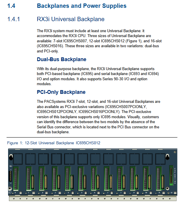
Universal backplane IC695CHS007/012/016 7/12/16 supports PCI+serial dual bus, some support expansion slots (12/16 slot models) IC695 series power supply
The serial expansion backplane IC694CHS392/398 10/5 only supports serial bus and requires installation of the expansion power supply IC694 series power supply on the left side
Compatible with backplane IC693CHS392/398/393/399 5/10 Series 90-30 expansion/remote backplane, RX3i system compatible with IC693 series power supply
(2) Power module (core specifications)
Module Type Model Example Input Voltage Output Power Core Output Applicable Backboard
Universal Backplane Power Supply (AC Input) IC695PSA040 120/240Vac/125VDC 40W 3.3V/5.1V/24V Relay Power Supply Universal Backplane
Universal Backplane Power Supply (DC Input) IC695PSD180 18~30Vdc 80W 3.3V (60W)/5.1V (60W)/24V (75W) Universal Backplane
Expansion Backpanel Power Supply (High Capacity) IC694PWR330 85~264Vac/100~300VDC 30W 5V (30W)/24V Relay (15W)/24V Isolation (20W) Serial Expansion Backpanel
Expansion Backpanel Power Supply (DC Input) IC694PWR331 12~30Vdc (Start ≥ 18V) 30W 5V (30W)/24V Relay (15W)/24V Isolation (20W) Serial Expansion Backpanel
(3) Classification of Core I/O Modules
Discrete input module (some key models) | Model | Signal type | Number of channels | Core parameters | Isolation level
|System 1500V DC optical isolation|
Discrete output module (some key models) | Model | Signal type | Number of channels | Output current | Protection function |
Simulation and HART module
Analog input: Supports 4-20mA, voltage RTD、 Thermocouple signal, channel number 4-16, accuracy 0.1-0.25% span, some with advanced diagnostic function;
Analog output: Supports 4-20mA/Voltage signals, with 2 to 8 channels and an accuracy of 0.25 to 0.4% span;
HART module: IC695ALG626/628 (input), IC695ALG728 (output), supports analog signal+digital communication overlay, compatible with HART smart transmitter.
Special function module
High speed counting module: IC694APU300/305, IC695HSC304/308, supporting a counting frequency of 1.5MHz;
Motion control module: IC694DSM314/324, IC695PMM335 (multi axis);
Communication module: Supports protocols such as PROFINET (IC695PNC/PNS series), PROFIBUS (IC695PBM/PBS series), DeviceNet (IC694DNM200), etc.
System installation and deployment specifications
(1) Installation foundation requirements
Physical installation:
The backboard needs to be installed horizontally, with a reserved ventilation space of 10cm (4in);
The installation environment should be kept away from high temperature sources (transformers, power resistors) and strong electromagnetic interference sources (relays, motors);
The protection level of the cabinet shall not be lower than IP20, and the pollution level shall be G3.
Grounding specifications:
The backplane needs to be connected to the cabinet grounding bar through AWG # 12 or above grounding wire, with low impedance grounding resistance;
Single point grounding of the shielding layer of analog signal cables (source or module end);
All backboards share the same system grounding reference point.
(2) Power supply and expansion deployment
Power supply connection:
Universal Backplane Power Supply: The IC695 series power supply supports 120/240VAC or 24Vdc input, and attention should be paid to polarity anti reverse connection;
Expansion backplane power supply: The IC694 series power supply needs to be installed in the leftmost slot of the expansion backplane;
Redundant power supply: Multiple IC695PSA140/PSD140/PSD180 can be configured with load sharing or power redundancy, requiring a unified power source polarity.
Extended deployment:
Expansion condition: The 12/16 slot universal backplane requires the installation of a serial bus transmission module (IC695LRE001);
Expansion cable: Supports IC693CBL series prefabricated cables, with a maximum distance of 15m for expansion backboards and a maximum distance of 213m for remote backboards;
Termination requirement: The last extension/remote backplane must be equipped with a terminal resistor (IC693ACC307).
(3) Module installation and hot plug
Operation type key rule support module
Hot plugging requires operation while the system is powered on, and most IC695/IC694 series I/O modules (such as IC695ALG series, IC694MDL series) need to be fully inserted/removed within 2 seconds
Hot plugging is prohibited and must be performed with power off, otherwise the device's CPU module, power module (non redundant), and LRE001 expansion module will be damaged
Installation sequence: First install the backplane → power module → CPU module → I/O module, all modules
Key points of configuration and maintenance
(1) Module configuration rules
Slot restriction:
Universal backplane slot 0 only supports IC695 power module;
CPU modules (except CPE302/305) occupy 2 slots and cannot be installed in expansion slots;
The expansion module (LRE001) can only be installed in the rightmost slot of the 12/16 slot universal backplane.
Load calculation:
The power load needs to accumulate the 3.3V/5V/24V current requirements of all modules, not exceeding the rated output of the power supply;
Example: 12 slot backplane+CPU310+8 I/O modules, total load required ≤ 40W output of IC695PSA040.
(2) Maintenance and troubleshooting
Replacement of vulnerable parts:
Fuse: The power module has built-in 2A/5A fuses (model 44A724627 series), which need to be replaced with the same specifications;
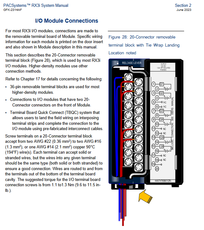
Terminal block: pluggable terminal block (20/36 pins), the on-site power supply must be disconnected before replacement.
Common troubleshooting:
Power failure: Check the power LED (POWER/P/S FAULT/OVERTEMP/OVERLOAD) and verify the input voltage and load;
Communication failure: When there is no response from the expansion backplane, check the LED status of the LRE001 module, the connection of the expansion cable, and the terminal resistance;
Module malfunction: Check the specific module malfunction code through the CPU malfunction table and verify the module wiring and slot configuration.
Preventive maintenance:
Regular cleaning: Clean the backplate cooling channel and module dust every month;
Insulation testing: Measure the insulation resistance of the module with a 500VDC insulation meter every year, and it is qualified if it is ≥ 1M Ω;
Environmental monitoring: Ensure that the temperature inside the cabinet is ≤ 60 ℃ to avoid condensation.
- YOKOGAWA
- Reliance
- ADVANCED
- SEW
- ProSoft
- WATLOW
- Kongsberg
- FANUC
- VSD
- DCS
- PLC
- man-machine
- Covid-19
- Energy and Gender
- Energy Access
- Renewable Integration
- Energy Subsidies
- Energy and Water
- Net zero emission
- Energy Security
- Critical Minerals
- A-B
- petroleum
- Mine scale
- Sewage treatment
- cement
- architecture
- Industrial information
- New energy
- Automobile market
- electricity
- Construction site
- HIMA
- ABB
- Rockwell
- Schneider Modicon
- Siemens
- xYCOM
- Yaskawa
- Woodward
- BOSCH Rexroth
- MOOG
- General Electric
- American NI
- Rolls-Royce
- CTI
- Honeywell
- EMERSON
- MAN
- GE
- TRICONEX
- Control Wave
- ALSTOM
- AMAT
- STUDER
- KONGSBERG
- MOTOROLA
- DANAHER MOTION
- Bentley
- Galil
- EATON
- MOLEX
- Triconex
- DEIF
- B&W
- ZYGO
- Aerotech
- DANFOSS
- KOLLMORGEN
- Beijer
- Endress+Hauser
- schneider
- Foxboro
- KB
- REXROTH
- YAMAHA
- Johnson
- Westinghouse
- WAGO
- TOSHIBA
- TEKTRONIX
- BENDER
- BMCM
- SMC
- HITACHI
- HIRSCHMANN
- XP POWER
- Baldor
- Meggitt
- SHINKAWA
- Other Brands
- UniOP
- KUKA
- IBA
- Beckhoff
- ADLINK
-
Beckhoff CP6500-1012-0060 - Control Cabinet PC Interface Unit
-
Beckhoff FC5202-0000 - 2-Channel DeviceNet Master PCI Interface Card
-
Beckhoff CP6606-0001-0020 - 7-Inch Economy Panel PC Touch
-
Beckhoff CP2921-0010 - Multi-Touch Integrated Control Panel Display
-
Beckhoff CP7802-0001-0010 - 15-Inch Touch Screen Control Panel HMI
-
Beckhoff C6920-0050 - Control Cabinet Industrial PC
-
Beckhoff BK9105 - EtherNet/IP Bus Coupler Network Interface
-
Beckhoff 31 Modules - Bus Terminal Slice I/O Lot Assortment
-
Beckhoff CX2020-0120 - Embedded PC Basic CPU Module 8GB CFast Card
-
Beckhoff CP7001-0000 - HMI Control Panel Touch Screen
-
B&R 7EX484.50-1 - System 2005 Controller Base Module Slots
-
Beckhoff EK1322 - 2-Port EtherCAT P Extension Feed-In Terminal
-
Beckhoff CP6606-0001-0020 - 7-Inch Single-Touch Economy Panel PC
-
Beckhoff CP6607-0001-0000 - Economy Installation Operator Panel PC 5.7-Inch
-
Beckhoff AX5103-0000-0200 - Digital Compact Servo Driver 3 Phase
-
Beckhoff CP7802-0001-0010 - 15-Inch Touch Screen Control Panel
-
Beckhoff AX8620 - Power Supply Module Axis System
-
Beckhoff CX2030-0121 - Embedded PC Controller Module
-
Beckhoff CP6606-0001-0020 - 7-Inch Economy Panel PC Touch Screen
-
Beckhoff CX2030-0121 - Embedded PC CPU Module Windows Standard 7
-
Beckhoff BX3100-0000 - PROFIBUS DP Bus Terminal Controller
-
Beckhoff CX1020-0000 - Controller Set with Power Supply Unit
-
Beckhoff EK1100 - EtherCAT Coupler Terminal Module Set
-
Beckhoff CP7002-1043-0010 - HMI Display Panel with Control Panel Bracket
-
Beckhoff AM8031-0D10-0000 - Synchronous Servo Motor
-
Beckhoff CX5130-0175 - Embedded PC 4GB RAM Controller
-
Beckhoff CX5130-0155 - Embedded PC Automation Controller
-
Beckhoff C6930-0010 - Control Cabinet Industrial PC Core Duo
-
Beckhoff CP3924-0000 - Multi-Touch Control Panel Display
-
Beckhoff AM8023-0F20-0000 - Synchronous Servo Motor
-
B&R KL3362 - Bus Terminal Thermocouple Input Module
-
Beckhoff AL2006-0000-0000 - Linear Servo Motor Three Phase
-
Beckhoff CX5140-0155 - Embedded PC CPU Controller Module
-
Beckhoff FC9002 - Ethernet PCI Network Interface Card
-
Beckhoff CP7203-0021-0040 - Built-In Panel PC 19-Inch Touch Screen
-
Beckhoff C6930-0020 - Control Cabinet Industrial PC HDD CF Card
-
Beckhoff CX2900-0033 - Memory Card CFast Storage
-
Beckhoff CP6201-0001-0020 - Built-In Panel PC Display
-
b+m surface systems C6930-1121-0060 - Industrial PC Beckhoff Core i7
-
Beckhoff CP2221-0010 - Multi-Touch Built-In Panel PC
-
Beckhoff C6017-0010 - Ultra-Compact Industrial PC
-
Beckhoff FC5102-0000 - 2-Channel CANopen PCI Interface Card
-
Beckhoff CP7021-0000-0000 - HMI Control Panel Interface
-
Beckhoff CP2216-0020 - Multi-Touch Built-In Panel PC
-
Beckhoff C6140 - Industrial PC Tower System Pentium 4
-
Beckhoff AM3033-1E40 - Servo Motor with Gearbox Assembly
-
Beckhoff CX9020-0115 - Embedded PC CPU Controller Module
-
Beckhoff CP6809-0001-0000 - Built-In Control Panel HMI Terminal
-
Beckhoff CP3919-0000 - Multi-Touch Control Panel Touchscreen Monitor
-
Beckhoff AM8053-0LHB-0000 - Synchronous Servo Motor
-
Beckhoff C6920-1028-0000 - Control Cabinet Industrial Computer PC
-
Beckhoff CX1100-0014 - Power Supply Unit for CX1030
-
Beckhoff CX9001-0101 - Embedded PC CPU Controller Module
-
Beckhoff CP3916-1428-0000 - Control Panel Multi-Touch Monitor
-
Beckhoff CP7037-1027-0010 - HMI Built-In Control Panel PC
-
Beckhoff CX1020-0120 - CPU Module DVI USB Windows Standard
-
Beckhoff CX5020-0121 - Embedded PC Controller Module
-
Beckhoff EL5042 - 2-Channel Encoder Interface BiSS C EtherCAT Terminal
-
Beckhoff CP7201-0021-0040 - Built-In Panel PC Touch Monitor
-
B&R X20-RT-8401 - reACTION Technology Module I/O Block
-
Beckhoff CP2915-0010 - HMI Control Panel Display Touch Screen
-
Beckhoff EL7221 - Servomotor Cyber Terminal EtherCAT Module
-
Beckhoff CX5140-0175 - Embedded PC CPU Module
-
Beckhoff C6017-0010 - Ultra-Compact Industrial PC
-
Beckhoff CX2020-0130 - Embedded PC Basic CPU Module
-
Beckhoff CX1030-0011 - Basic CPU Module Windows CE 6.0
-
Beckhoff AM8043-1E00-0000 - Synchronous Servo Motor
-
Beckhoff CX1020-0110 - CPU Module Controller Interface Bundle
-
Beckhoff C6930-1069-0030 - Control Cabinet Industrial PC Mainboard CB3054-0001
-
Beckhoff KL9528 - Power Supply Terminal Module
-
Beckhoff AM8053-0K20-0000 - Synchronous Servo Motor
-
Beckhoff CX5020-1111 - Embedded PC Controller Module
-
Beckhoff CX5130-0175 - Embedded PC CPU Module Intel Atom
-
Beckhoff CP6401-1024-0040 - Husky Display Control Panel HMI Terminal
-
Beckhoff CP2616-0000 - Multi-Touch Display Automation Panel PC
-
Beckhoff CP7921-1075-0000 - 12-Inch HMI Control Panel ELO Touch
-
Beckhoff C6930-0060 - Control Cabinet Industrial PC SSD
-
Beckhoff AX5112-0000 - Digital Compact Servo Drive 3 Phase
-
Beckhoff C6930-0040 - Control Cabinet Industrial PC Intel Core i5
-
Beckhoff CP2616-0000 - Multi-Touch Display Automation Panel PC
-
Beckhoff KL1414 - 4-Channel Digital Input Bus Terminal
-
Beckhoff CX1020-0000 - Basic CPU Module Controller
-
Beckhoff CP6201-1008-0000 - 12-Inch Built-In Panel PC
-
Beckhoff CP7021-0000 - HMI Control Panel Display Screen
-
Beckhoff AX5106-0000 - Digital Compact Servo Drive
-
Beckhoff BX3100-0000 - Profibus DP Bus Terminal Controller
-
Beckhoff CP2916-0000 - Multi-Touch Built-In Control Panel
-
Beckhoff C6925-0030 - Fanless Control Cabinet Industrial PC
-
Beckhoff C6330 - Industrial PC Motherboard Boser HS6237 Celeron
-
Beckhoff AM3033-0C00-0000 - Synchronous Servo Motor
-
Beckhoff CP7232-0001-0030 - Control Panel PC HMI
-
Beckhoff CX5020-0122 - Embedded PC CPU Module
-
Beckhoff AM8043-0H10-0000 - Rotary Synchronous Servo Motor
-
Beckhoff CP3924-0010 - Multitouch Control Panel HMI
-
Beckhoff CX9020-0110-1005 - Embedded PC Basic CPU Module
-
Beckhoff BK9105 - EtherNet/IP Bus Coupler
-
Beckhoff CX1500-M310 - Profibus Master Fieldbus Extension Module
-
Beckhoff CX1500-M510 - PROFIBUS Master Fieldbus Extension Module
-
Beckhoff CP9922.0 - TTL-TX Display Transmitter Card
-
Beckhoff CP9010_1 - ISA Slot Interface Card
-
Beckhoff NRL75-DC30S15B - LCD Inverter Board
-
Beckhoff LTD121C30S - Toshiba LCD Display Panel
-
Beckhoff CP7732-1207-0030 - Operating Terminal Panel PC HMI
-
Beckhoff C5102-0010 - Rackmount Industrial Computer PC5000
-
Beckhoff C6015-0010 - Ultra-Compact Industrial PC
-
Beckhoff CB1056-0001 - Industrial PC Motherboard Mainboard
-
Beckhoff AX5103 - Digital Compact Servo Amplifier 1 Axis
-
Beckhoff AM8052-0J00-9000 - Rotary Synchronous Servo Motor
-
Beckhoff CP7932-0002-0000 - Control Panel HMI Display
-
Beckhoff CB1061-0001 - Industrial PC Motherboard Mainboard
-
Beckhoff C5102-0060 - 19-inch Rackmount Industrial PC
-
Beckhoff EL7342 - 2 Channel DC Motor Motion Interface EtherCAT Terminal
-
Beckhoff CX5120-0135 - Embedded PC CPU Module Intel Atom
-
Beckhoff CB1061-G4 - Industrial PC Motherboard Mainboard
-
Beckhoff CX50100121 - Embedded PC CPU Module
-
Beckhoff CX1030-0013-1002 - Basic CPU Module Intel Pentium M
-
Beckhoff CP7802-1075-0010 - Control Panel Touch Screen HMI
-
Beckhoff AM8023-0E20-0000 - Rotary Synchronous Servo Motor
-
Beckhoff EL5032 - 2 Channel Encoder Interface EnDAT EtherCAT Terminal
-
Beckhoff CX5130-0175 - Embedded PC CPU Module Intel Atom
-
Beckhoff CA4040-0000 - PCI Ethernet Network Board
-
Beckhoff C3340 - Panel PC Industrial Workstation
-
Beckhoff EL3068 - 8 Channel Analog Input EtherCAT Terminal 0-10V
-
Beckhoff EL1889 - 16 Channel Digital Input EtherCAT Terminal
-
Beckhoff C6640-0050 - Control Cabinet Industrial PC Intel Core i7
-
Beckhoff PC MIC 3230 TP - Industrial Panel PC Touch Screen
-
Beckhoff CX2040-0135 - Embedded PC Industrial CPU Module
-
Beckhoff CP6202-1020-0010 - Built-in Panel PC HMI

K-JIANG

Add: Jimei North Road, Jimei District, Xiamen, Fujian, China
Tell:+86-15305925923