
K-WANG


Foxboro FBM224 Modbus ® communication module
Foxboro FBM224 Modbus ® communication module
Module core positioning and core value
1. Core positioning
FBM224 is a product specifically designed for Foxboro Evo ™ Process Automation System and I/A Series ® The core function of the Modbus master communication interface module in system design is to build a communication bridge between Modbus slave devices (such as PLCs, field I/O devices, and smart meters) and system control processors (FCP280, FCP270/ZCP270, CP60), achieving seamless integration of device data from different vendors with the Foxboro system control database.
2. Core values
Multi protocol and multi interface compatibility: Supports RS-232, RS-422, and RS-485 communication interface standards simultaneously, adapting to the communication needs of the vast majority of Modbus slave devices without the need for additional converters;
Flexible redundancy deployment: supports port redundancy configuration (1&2 ports, 3&4 ports can be combined into logical redundancy ports), adapts to dual port Modbus devices, and improves communication link reliability;
Large capacity data exchange: A single module can connect to 64 Modbus slave devices, support 2000 DCI data connections, and can cover up to 32000 digital I/O points, meeting the data transmission needs of medium to large industrial scenarios;
Adaptation to hazardous environments: With the use of specialized terminal components (TA), it can be installed in Class I, Division 2, and Zone 2 hazardous areas, suitable for high-risk industries such as petrochemicals and natural gas;
Plug and play and easy maintenance: supports hot swappable design, module replacement does not require disconnecting on-site wiring, power and communication cables, reducing the risk of system shutdown.
Hardware composition and physical characteristics
(1) Core hardware structure
1. Module body
Shell material: Made of sturdy extruded aluminum alloy shell, it has both physical protection and electrical shielding functions, and can resist vibration, impact, and electromagnetic interference in industrial sites;
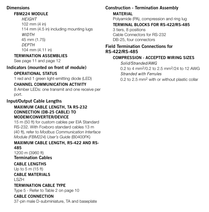
Size specifications: Height 102mm (including installation ears 114mm) x Width 45mm x Depth 104mm, Weight approximately 284g (10oz), in compliance with the Compact 200 Series module standard size, suitable for modular base plate installation;
Status indicator lights: The front integrates 10 LED indicator lights, including 1 red (fault) and 1 green (running) status light, as well as 8 amber communication lights (1 transmitter light and 1 receiver light per port), providing real-time feedback on the module's operating status and port communication activity.
2. Terminal Component (TA)
As the wiring hub between modules and field devices, TA has the following core designs:
Installation method: Supports 32mm or 35mm DIN rail installation, suitable for industrial standard installation scenarios;
Wiring interface:
RS-232: 4 standard DB-25 male connectors, each port is equipped with 24 DIP switches, and RS-232 signal pins can be flexibly configured (such as Clear to Send and Request to Send interconnection);
RS-422/RS-485: Three layer compression or ring terminal block, supporting 0.2-4mm ² solid/multi strand wires (24-12 AWG), suitable for on-site wiring of different wire diameters;
Key function: Built in switchable terminal resistors for each port (used for RS-422/RS-485 bus matching), reducing signal reflection interference; The material is polyamide (PA), which combines temperature resistance and mechanical strength;
Size and weight: Compressed TA length 216mm, weight 320g; Circular wiring TA length 250mm, weight 454g, can be selected according to on-site wiring requirements.
3. Connect the cable
Terminal cable: used for the connection between TA and modular base plate, using 37 pin D-subminiature male head, made of low smoke and halogen-free (LSZH) material, supporting four lengths of 1.0m, 2.0m, 3.0m, 5.0m (corresponding to models RH928AW/AZ, etc.), with a maximum extension of 5m (16 feet), suitable for different installation distance requirements;
On site communication cable:
RS-232: Following EIA standards, custom cables can be up to 15m (50 feet) long, while Foxboro standard cables can be up to 13m (40 feet) long;
RS-422/RS-485: Using shielded twisted pair cables, the longest communication distance can reach 1200m (3960 feet), meeting the requirements of long-distance distributed deployment.
(2) Installation and deployment features
1. Bottom plate installation
The module needs to be installed on the Foxboro modular base plate, which supports 4-slot or 8-slot FBM installation. It can be installed horizontally/vertically on DIN rails or on a 19 inch rack (with accompanying installation kit); The bottom board integrates FBM signal connectors, redundant 24V DC power interfaces, and I/O cable interfaces to ensure stable power supply and signal transmission of the module.
2. Hot swappable design
Modules can be directly plugged and replaced without the need to disassemble on-site equipment wiring, power cables, or communication cables, significantly reducing maintenance downtime and improving system availability.

Communication function and protocol support
1. Modbus protocol adaptation
Working mode: only supports Modbus RTU mode (asynchronous communication), does not support ASCII mode;
Function code support: Covering commonly used core industrial function codes to meet all data reading and writing requirements, as follows:
Function code function description application scenario
01 Read coil status, read digital output status (such as valve switch, indicator light status)
02 Read input status Read digital input status (such as sensor trigger signals, equipment fault feedback)
03 Read and hold registers to read device configuration parameters, cumulative data, etc. (such as cumulative flow rate of flow meters)
04 Read input register to read real-time measurement data (such as analog conversion values of temperature, pressure, and flow)
05 Mandatory single coil control for single digital output (such as starting/stopping motors, opening/closing valves)
06 Preset single register configuration device for individual parameters (such as setting pressure threshold, flow upper limit)
Self check the communication link between the 08 circuit diagnostic testing module and the slave device to troubleshoot connection faults
15. Mandatory batch control of multiple digital outputs with multiple coils (such as simultaneously starting a group of devices)
16 preset multi register batch configuration of device parameters (such as batch setting of measurement ranges for multiple instruments)
Data format: Supports 8-bit characters, configurable parity check (odd check/even check/no check), configurable stop bit (1 bit/2 bits), adaptable to communication parameter settings of different slave devices.
2. Port configuration and communication capability
(1) Port characteristics
The module is equipped with four independent serial communication ports, each of which can be individually configured as an RS-232, RS-422, or RS-485 interface without the need for hardware modification. Switching can be completed through software configurator;
Port redundancy function: Ports 1&2 and 3&4 can be configured as a single logical port, and can be connected to dual port Modbus devices with redundant cables to achieve communication link redundancy and avoid data interruption caused by single point failures.
(2) Communication parameters
Transmission rate: Supports 10 speeds including 300, 600, 1200, 2400, 4800, 9600, 19200, 38400, 57600, and 115200 baud, and can be flexibly selected according to communication distance and device requirements (low-speed is recommended for long-distance communication, high-speed is recommended for short distance high-speed transmission);
From device address: Supports a range of 1-247 addresses, which can cover the addressing requirements of Modbus devices in the vast majority of industrial scenarios.
3. Data interaction capability
(1) Access capacity
A single module can support up to 64 Modbus slave devices (the actual number is affected by device type, data volume, and scanning rate);
A single module can support up to 2000 distributed control interface (DCI) data connections, covering:
2000 analog I/O values (integer or IEEE single precision floating-point type);
32000 digital I/O values (calculated by packing 32 digital points per connection);
Mixed analog and digital data connection.
(2) Data processing and updating
As a Modbus master, the module periodically polls the input data from the device according to the user configured scanning rate, and the output request is immediately executed after being sent by the control processor, without being limited by the polling cycle;
The access speed of the control station to FBM224 data can reach up to 500ms at the fastest, with low data update latency, meeting real-time control requirements;
Support data format conversion: The module automatically converts raw data from the device (2-byte/4-byte signed/unsigned integers, 4-byte IEEE floating point types, binary values) into Foxboro system compatible format and stores it in the system database for use by plant management functions and operator interfaces; Simultaneously supporting byte order and bit order switching, adapting to data storage formats of devices from different manufacturers.
Configuration tools and operating procedures
1. Configuration tool
Provide Windows ® Compared to Solaris ® There are two versions of configurator for operating systems, namely port configurator and device transaction configurator. During the configuration process, the validity of parameters (such as rate range and address legality) is automatically verified to avoid configuration errors.
(1) Port configurator
Used to set communication parameters for each port, including:
Communication interface standard (RS-232/RS-422/RS-485);
Transmission rate, parity check, stop bit;
Enable/disable port redundancy mode (1&2 ports, 3&4 ports).
(2) Device Transaction Configurator
Used to set communication transaction parameters for slave devices, including:
Scanning rate: configurable from 0.5 seconds to 255 seconds, default 500ms, adjustable according to device response speed and real-time data requirements;
Phase setting: When the scanning rate is an integer multiple of the base period, specify the specific scanning period to distribute the communication load between the module and the device;
Transaction details: Function code, starting address of data, amount of data transmitted in a single transaction, up to 64 independent transaction configurations supported by a single device.
2. Control block support
The module is compatible with Foxboro standard DCI control block types, through Foxboro Evo Control Editors、I/A Series Configuration Component(IACC)、Integrated Control Configurator(ICC) Or FoxCAE ™ The software is configured in the control processor, and the control block interacts with Modbus slave devices for data read and write through address mapping. The supported types of control blocks are as follows:
Function description of control block type
BIN binary input
BINR redundant binary input
BOUT binary output
IIN integer input
IOUT integer output
PAKIN packaging input (multi digit point packaging)
PAKOUT packaging output (multi digit point packaging)
PLSOUT pulse output
RIN Real Input (Floating Point Type)
RINR redundant real number input
ROUT Real Output (Floating Point Type)
Core performance parameters and environmental adaptability
1. Electrical performance
Power requirements: Redundant 24V DC power supply, voltage range+5%~-10% (i.e. 21.6V~25.2V DC), maximum power consumption 7W, maximum heat dissipation 7W, compatible with Foxboro standard redundant power supply (such as FPS480-24);
Channel isolation: Galvanic isolation is used between each communication channel and ground, which can withstand 600V AC voltage for 1 minute without damage, effectively avoiding ground loop interference and high voltage intrusion;
Fieldbus communication: Communicate with FCM (fieldbus communication module) or control processor through redundant 2Mbps module fieldbus, support A/B dual path switching, automatically switch to another path when one path fails, ensuring communication continuity.
2. Environmental adaptability
(1) Temperature and humidity
Module operating temperature: -20 ℃~+60 ℃ (-4 ℉~+140 ℉);
Terminal component operating temperature: -20 ℃~+70 ℃ (-4 ℉~+158 ℉);
Storage temperature: -40 ℃~+70 ℃ (-40 ℉~+158 ℉);
Relative humidity: 5%~95% (non condensing), suitable for industrial environments with high humidity and large temperature differences.
(2) Anti interference and protection
Electromagnetic Compatibility (EMC): Complies with the European EMC Directive 2004/108/EC, EN61326:2013 Class A emission standards and industrial immunity levels, including:
Electrostatic discharge (ESD): Contact 4kV, air 8kV;
Radiated field immunity: 10V/m at frequencies of 80-1000MHz;
Electric fast transient/pulse group: I/O, DC power supply and communication line 2kV;
Surge immunity: ± 2kV for AC/DC power lines, ± 1kV for I/O and communication lines;
Pollution level: Compliant with ISA S71.04 Class G3 (harsh environment) standard, resistant to industrial dust, oil pollution and other pollution;
Vibration and impact: Can withstand vibrations of 7.5m/S ² (0.75g) and 5-500Hz, suitable for the vibration environment generated by industrial field equipment operation.
Security certification and compliance
The module is certified through multiple regions and standards to ensure compliant use in different countries/regions and hazardous environments
Specific standards and instructions for certification types
Electrical Safety (US Canada) UL/UL-C certification, applicable to Class I, Groups A-D; Division 2; T4 temperature group shell system; As an associated device, provide non flammable communication circuits for Class I, Groups A-D hazardous areas; Meets the Class 2 circuit requirements of the National Electrical Code (NFPA 70 Article 725) and the Canadian Electrical Code (CSA C22.1 Section 16)
European certification for Low Voltage Directive 2006/95/EC and Explosion proof Directive 94/9/EC; DEMKO certification for EEx nA IIC T4, suitable for Zone 2 hazardous areas, as an associated device providing non flammable on-site circuits for Zone 2, Group IIC potentially explosive environments
Environmental compliant terminal components (TA) and terminal cables comply with the EU RoHS Directive 2002/95/EC and revised 2011/65/EU, restricting the use of harmful substances such as lead and mercury
Electromagnetic compatibility complies with CISPR 11 Industrial, Scientific, and Medical (ISM) Radio Frequency Equipment Electromagnetic Disturbance Limits, IEC 61000 series immunity standards (static electricity, radiation, surge, etc.)
Typical application scenarios and topology configuration
1. Applicable industries and scenarios
Core industries: petrochemical, natural gas, power, water treatment, manufacturing (such as automobiles, electronics) and other industrial fields that require multi device interconnection;
Typical applications:
Data exchange between PLCs from different manufacturers and Foxboro systems (such as connecting equipment status data from third-party PLCs to the Foxboro operator interface);
Intelligent instruments (such as flow meters, pressure transmitters) data acquisition (reading instrument measurement values through Modbus RTU);
Distributed I/O device control (controlling the output ports of remote I/O modules through Modbus commands);
Communication of hazardous area equipment (such as safety communication between sensors and systems in Zone 2 of the petrochemical industry).
2. Typical topology configuration
The module supports multiple Modbus network topologies and adapts to different on-site layout requirements. The core configuration is as follows:
(1) Redundant link configuration
Topology: Ports 1 and 2 are configured as redundant logical ports, while ports 3 and 4 are configured as redundant logical ports. They are respectively connected to dual port Modbus slave devices or to redundant links of single port devices through redundant cables;
Advantages: Avoiding data interruption caused by a single communication link failure, improving system reliability, and suitable for critical control circuits.
(2) Mixed interface configuration
Topology structure: Four ports are configured as different interfaces (such as one port for RS-232 connection to a modem, two ports for RS-422 direct connection to devices, and three&four ports for RS-485 multi-point bus connection to multiple instruments);
Advantages: Devices that can adapt to multiple communication interfaces simultaneously, without the need for additional interface converters, reducing system complexity.
(3) Remote distributed configuration
Topology structure: Multiple slave devices (such as flow meters and pressure sensors deployed along pipelines) are connected on a single bus through the 1200m long-distance transmission capability of RS-485 interface. The modules are deployed in the control room and the on-site devices are installed in a distributed manner;
Advantages: Reduce on-site wiring costs, simplify construction difficulties, and adapt to large-scale industrial scenarios.
Key selection and deployment considerations
1. Key selection points
Confirm the communication interface (RS-232/RS-422/RS-485) and Modbus mode (RTU mode required) of the device;
Determine whether the module capacity meets the requirements based on the number of devices (≤ 64) and data points (≤ 2000 DCI connections);
In hazardous environments, it is necessary to confirm the installation area level (Class I, Division 2 or Zone 2) to ensure that the module matches the certification of the TA;
When the communication distance exceeds 15m (RS-232) or requires multi-point connection, RS-485 interface is preferred.
2. Deployment precautions
Wiring specification: RS-422/RS-485 requires shielded twisted pair cables, and terminal resistors (configured through TA's DIP switch) should be enabled at both ends of the bus to avoid signal reflection; RS-232 wiring needs to match the device pin definition (adjusted through TA's DIP switch);
Power configuration: It is recommended to use redundant power supply in key scenarios to avoid module shutdown caused by power failure;
Electromagnetic interference protection: Modules and cables should be kept away from strong electromagnetic interference sources such as frequency converters and motors, and the shielding layer should be grounded at one end to reduce interference effects;
Software compatibility: Ensure that the control system software version meets the requirements (I/A Series v8.8+or Foxboro Evo v9.0+) to avoid incompatibility between configuration tools and the system.
- YOKOGAWA
- Reliance
- ADVANCED
- SEW
- ProSoft
- WATLOW
- Kongsberg
- FANUC
- VSD
- DCS
- PLC
- man-machine
- Covid-19
- Energy and Gender
- Energy Access
- Renewable Integration
- Energy Subsidies
- Energy and Water
- Net zero emission
- Energy Security
- Critical Minerals
- A-B
- petroleum
- Mine scale
- Sewage treatment
- cement
- architecture
- Industrial information
- New energy
- Automobile market
- electricity
- Construction site
- HIMA
- ABB
- Rockwell
- Schneider Modicon
- Siemens
- xYCOM
- Yaskawa
- Woodward
- BOSCH Rexroth
- MOOG
- General Electric
- American NI
- Rolls-Royce
- CTI
- Honeywell
- EMERSON
- MAN
- GE
- TRICONEX
- Control Wave
- ALSTOM
- AMAT
- STUDER
- KONGSBERG
- MOTOROLA
- DANAHER MOTION
- Bentley
- Galil
- EATON
- MOLEX
- Triconex
- DEIF
- B&W
- ZYGO
- Aerotech
- DANFOSS
- KOLLMORGEN
- Beijer
- Endress+Hauser
- schneider
- Foxboro
- KB
- REXROTH
- YAMAHA
- Johnson
- Westinghouse
- WAGO
- TOSHIBA
- TEKTRONIX
- BENDER
- BMCM
- SMC
- HITACHI
- HIRSCHMANN
- XP POWER
- Baldor
- Meggitt
- SHINKAWA
- Other Brands
- UniOP
- KUKA
- IBA
- Beckhoff
- ADLINK
-
ADLINK HPCI-14S12U - Industrial Control Backplane 12PCI Backplane PCI-14S Passive Backplane
-
ADLINK PCIe-GIE74C - image acquisition card 4-CH GigE Vision PoE+ Frame Grabber
-
ADLINK PCI-8164 - control card 4-Axis Advanced Motion Controller Board
-
ADLINK PCIe-U304 - 4 Port USB3 PCIe Frame Grabbers USB Screw Hole Card
-
ADLINK PCI-9112 - Multi-Function Data Acquisition Card DAQ Card
-
ADLINK PCI-7432 - 51-12013-0A50 4-CH Isolated Numérique I/O PCI Cartes Digital I/O Card
-
ADLINK PCA-6106P3-0C1 REV.C1 - backplane 6-Slot Passive Backplane Board
-
ADLINK PCI-7224 - 24-CH Opto-Isolated Digital I/O PCI Board
-
ADLINK CPCI-7433R(G) - Digital Input Board Rear I/O CompactPCI Card
-
ADLINK EBP-13E4 - 51-46703-0A30 Industrial PC Backplane Passive Backplane
-
ADLINK PCIE-HDV62 - Image acquisition card High Definition Video Frame Grabber
-
ADLINK EBP-13E4 - 51-46703-0A30 Industrial Backplane Board Passive Backplane
-
ADLINK 90111-B1 / CPCI-6770 - PCB CPU MODULE CompactPCI Single Board Computer
-
ADLINK PCI-7248 - DATA ACQUISITION PCI CARD 48-CH Parallel Digital I/O Board
-
ADLINK PCI-7230 - 51-12003-0a50 board PCI7230 32-CH Isolated Digital I/O Card
-
ADLINK PCI2A000CB - 51-20000-0B30 Multi-Function DAQ Card Baseboard
-
ADLINK PCI-8134-005 - 4-Axis Motion Controller Card
-
ADLINK PCI-7224 - 24-CH Opto-Isolated Digital I/O PCI Card
-
ADLINK PCI-7434 - 64-CH Isolated Digital Output Card
-
ADLINK PCI-8132 - motion control card 2-Axis Servo & Stepper Controller
-
ADLINK PCI-8134 - Motion Controller PCI Card 4-Axis Controller Board
-
ADLINK PCI-8164 - Motion Control Card 51-12406-0A40 4-Axis Controller
-
ADLINK 51-12001-0C20 - Circuit Board Data Acquisition Interface Module Hardware
-
ADLINK NuPR0-840 - industrial control motherboard Full-Size PICMG CPU Board
-
ADLINK PCI-7444 - 51-12023-0A10 card 128-CH Isolated Digital Output Board
-
ADLINK PCI-1612B - data acquisition card 4-Port RS-232/422/485 Serial Communication Card
-
ADLINK PCI-6208V 009 - 8/16-CH 16-Bit Analog Output Cards PCB-I-E-482=6BX3
-
ADLINK NUPRO-935A/LV - industrial control motherboard Full-Size PICMG SBC Board
-
ADLINK PCI-9114DG - Multi-Function DAQ Card Data Acquisition PCI Card
-
ADLINK ACL-7130 - Data acquisition card Isolated Digital I/O Board
-
ADLINK ABX-6300D-4E1-BP - board ABX6300D4E1BP Video Interface Expansion Card
-
ADLINK CPCI-6940 - CPCI-6940/D1539/M16-0(EA)-000E 6U CompactPCI Processor Board
-
ADLINK NuPRO-760 - industrial control motherboard Half-Size PICMG SBC CPU Board
-
ADLINK IMB-M42H (G)-0020 - industrial control motherboard LGA1155 Micro-ATX Mainboard
-
ADLINK RTV-24 / PCI-MP4S - 51-12519-1C30 4-Channel Real Time Video Capture Board
-
ADLINK PCI-8134 - 4-Axis Servo & Stepper Motion Controller Card
-
ADLINK MXC-6101D - V.PC000.002.ST.00 Box PC Configurable Embedded Computer
-
ADLINK PCI-8134A - 51-12421-0A10 Motion Control Card 4-Axis Controller Card
-
ADLINK DIN-100S / DIN-100SA1 - Technology SCSI-II TB 100-PIN Terminal Block Board
-
ADLINK DIN-812M001 / DIN812M001 - 51-14034-0A1 51140340A1 Terminal Module Breakout Interface
-
ADLINK PCI-8164 - Servo motion control 4-Axis Advanced Controller Card
-
ADLINK PCIe-GIE64 - Acquisition card GigE Vision PoE+ Frame Grabber
-
ADLINK M-302 - Industrial control motherboard ATX PC Board Mainboard
-
ADLINK PCI-8134 - Motion Controller PCI Card 4-Axis Controller Board
-
ADLINK PCI-RTV24 - Image capture card Analog Video Frame Grabber
-
ADLINK PCI-8102 - Motion control card 2-Axis Servo & Stepper Controller Board
-
ADLINK PCI-9112 REV.B1 - Card Multi-Function Data Acquisition Card
-
ADLINK HSI-DI32-M-N / HSL-TB32-M-DIN - Discrete I/O MODULE Distributed Automation Module System
-
ADLINK PCI-7296 - IO card REV.A3 96-CH Parallel Digital I/O Card
-
ADLINK DIN-814P-A4 / 814Y - terminal board Motion Control Interface Block
-
ADLINK DIN-814P-A4 - 51-14056-0A10 PCB-I-E-2736=ZA01 Screw Terminal Board Breakout
-
ADLINK M-322 - motherboard Industrial Control Computer Mainboard
-
ADLINK NUPRO-406 REV:B1 - industrial control motherboard Full-Size PICMG CPU Board
-
ADLINK AMP-204C - card DSP-Based 4-Axis Advanced Pulse-Train Controller
-
ADLINK HPCI14S REV.B1 - industrial computer baseboard 14-Slot Passive Backplane
-
ADLINK PCI-7250 - 8-CH Relay Output & 8-CH Isolated DI PCI Card
-
ADLINK EBP-13E2 - baseplate Passive Backplane Industrial Computer Chassis Board
-
ADLINK LPCI-3488A - PCI-GPIB card 51-12801-0A30 acquisition card IEEE-488 Interface Board
-
ADLINK PCI-6216V-GL - 51-12201-0C30 16-CH 16-Bit Voltage Analog Output Card
-
ADLINK ACL-8454 - 16-CH Isolated Digital I/O & 4-CH Counter Card
-
ADLINK HPCI-9S7U - backplane Passive Backplane Compatible with NuPRO-A301 852 841 842
-
ADLINK DAQ-2010-007 - Simultaneous-Sampling Multi-Function Data Acquisition Card
-
ADLINK MP-C154 - 51-64205-0A10 Motion Control Card 4-Axis Controller Board
-
ADLINK MXE-202/mSSD16B/WiFi-BT - Matrix Rugged I/O Platform Embedded Fanless Computer
-
ADLINK CM-920-R-17 - PC/104-Plus Single Board Computer Module Intel Celeron M
-
ADLINK PCI-7250 NSMP - 8-CH Relay Output & 8-CH Isolated DI Card
-
ADLINK PCI-8164 - 4-Axis Motion Controller PCI Card W/ Cable and Breakout Box
-
ADLINK EMX-100 - Ethernet-based 4-axis Motion Controllers Distributed Motion Module
-
ADLINK PCI-8134A - Press control card 4-Axis Motion Controller Board
-
ADLINK M-845EG REV:3.2 - industrial motherboard Pentium 4 Socket 478 Micro-ATX
-
ADLINK PCI-9114A Rev A2 DG - card High-Resolution Multi-Function Data Acquisition Board
-
ADLINK IEC-915GV - REV 1.1 Industrial motherboard Socket 478 CPU Board
-
ADLINK PCI-9111DG(G) - Data Acquisition Card Multi-Function DAQ Card
-
ADLINK HPCI-15S10 REV:B2 - Industrial computer base plate Passive Backplane Board
-
ADLINK NuPR0-840 / NuPR0-840DV - industrial control motherboard Full-size PICMG CPU Board
-
ADLINK RTV-24 / PCI-MP4S - 51-12519-1C30 4-Channel Real Time Video Capture Board
-
ADLINK NUPRO-780 - industrial control motherboard Pentium III Single Board Computer
-
ADLINK PCI-7296 - 0050 card 96-CH Opto-Isolated Parallel DIO Card Set
-
ADLINK NUPRO-780 - industrial control motherboard PICMG Full-Size SBC
-
ADLINK PCI-7248 - 51-12006-0A3 002 Pci 7248 48-CH Parallel Digital I/O Card
-
ADLINK PCI-7230 - 32-CH Isolated Digital I/O Card
-
ADLINK AMP-204C - motion control card 4-Axis Advanced Controller Board
-
ADLINK PCI-1714UL - Card Ultra High-Speed 4-CH Simultaneous Sampling DAQ
-
ADLINK NuPRO-E330 - industrial computer equipment motherboard PICMG 1.3 SHB SBC
-
ADLINK AMP-204C - DSP-Based 4-Axis Advanced Pulse-Train Motion Controller Module
-
ADLINK PCI-7256 - 001 51-12206-0A2 REV.A2 LPCI-7256 16-CH Latching Relay Output Card
-
ADLINK ND6050 - NUDAM DIGITAL I/0 MODULE Distributed I/O Unit
-
ASEM BM100 - Box PC Embedded Fanless Industrial Computer
-
ADLINK PCI-7250 - PCI Acquisition Card 8-CH Relay Output & Isolated DI Board
-
ADLINK PCI-8164 - Servo motion control 4-Axis Controller Card
-
ADLINK NuPRO-A40H - Industrial Motherboard 51-41807-1A30 OSP LGA1155 H61
-
ADLINK ADMAX X300 SERVER - 51066010-0A30 motherboard Multi-Processor Mainboard
-
ADLINK CMe-GIE62+ - 51-32903-0A30 control card PC/104-Plus GigE Vision Frame Grabber
-
ADLINK NUPRO-780 - industrial control motherboard Full-Size PICMG SBC CPU Board
-
ADLINK ETX-AT-N270-18/GKTEL - 51-71111-OB10 motherboard ETX CPU Module Board
-
ADLINK DIN-812M - interface module Terminal Block Connection Board
-
ADLINK IMB-M42H - industrial control motherboard LGA1155 Micro-ATX Mainboard
-
ADLINK PXIS-2508 - 8-slot 3U PXI Instrument Chassis Power Hardware Assembly
-
ADLINK AMP-208C - Motion Control card DSP-Based 8-Axis Pulse-Train Controller
-
ADLINK PCI-9111 / PCI-9111DG - Multi-Function Data Acquisition Card DAQ Board
-
ADLINK IEEE-488 GPIB card - Bus Interface Controller Communication Board
-
ADLINK RTV-24 - 51-12519-1C30 image acquisition card Video Frame Grabber Card
-
ADLINK TB-24P/24-01 - Board 24 Way Screw Terminal Breakout Board
-
ADLINK HSL-DI16DO16-DB-NN - 51-23015-0A40 Distributed Discrete I/O Module Set
-
ADLINK PCI-7442 - switch quantity card data acquisition card 64-CH Isolated Card
-
ADLINK ACL-7130 REV. B2 - industrial control capture card Isolated Digital I/O PCI Card
-
ADLINK PCI-6S / PCI6S - Backplane 6-Slot Passive Backplane Chassis Board
-
ADLINK ACL-8113A - card Isolated Digital Input Card
-
ADLINK CPCI-6208V-003 - board cPCI CompactPCI 8-CH Analog Output Card
-
ADLINK DIN-100S-01(G) - SCSI 100-Pin Terminal Block Interface Board
-
ADLINK PCI-7433 - Isolated Digital Input Card 64-CH
-
ADLINK PCI-9812 - Synchronous sampling analog input card High-Speed DAQ Board
-
ADLINK PCI-7434 REV.B1 - PLOTECH PCB-I-E-1182=6EX2 64-CH Isolated Digital Output Card
-
ADLINK PCIe-RTV24 - 51-18016-0A20 4-CH Real-Time Video Capture Card PCIe Frame Grabber
-
ADLINK PCI-8144 / PCI-8144N - Motion control card 4-Axis Stepper Motor Controller
-
ADLINK DIN-68S-01 - terminal board 68-Pin Connector Terminal Block
-
ADLINK MP-C154 - Motion control card 4-Axis Advanced Controller Card
-
ADLINK PCI-7248 (G) - Motherboard 48-CH Parallel Digital I/O Card
-
ADLINK MXE-1301(G) - Intel Atom D2550+NM10 MXE 1300 Series 93-4130-0030 Embedded Computer
-
ADLINK PRO-841 Rev 2.0 / PRO-060907000670 - CPU 2.26GHz & RAM Industrial PC Board
-
ADLINK NuPRO-E330 - Industrial Motherboard System Host Board PICMG 1.3 SHB
-
ADLINK EBP-13E2 - Passive Backplane Industrial Chassis Baseboard
-
ADLINK PCI-8154 - 4-axis Motion Control Card Servo & Stepper Controller Board
-
ADLINK NuPrO-596 REV.B1 - industrial control motherboard Half-size PICMG CPU Board
-
ADLINK PCI-7852 / PCI-7851 - PLOTECH High-Speed Link Control Card Interface Board
-
ADLINK PCI-9112 - 51-12252-0D20 data acquisition card Multi-Function DAQ
-
ADLINK PCI-9112 - Circuit Board 51-12252-0C20 Multi-Function Data Acquisition Card
-
ADLINK NUPRO-761 REV:1.1 - industrial control motherboard PICMG Full-Size CPU Board

K-JIANG

Add: Jimei North Road, Jimei District, Xiamen, Fujian, China
Tell:+86-15305925923