
K-WANG


YASKAWA GA700 series AC frequency converter
Core objective: To guide professional technicians to complete the safe installation, wiring, parameter configuration, trial operation, and fault handling of frequency converters
Applicable restrictions: limited to industrial motor control only, not used in special fields such as life support systems, nuclear industry, etc
YASKAWA GA700 series AC frequency converter
Overview
Type: YASKAWA GA700 series AC frequency converter
Core objective: To guide professional technicians to complete the safe installation, wiring, parameter configuration, trial operation, and fault handling of frequency converters
Applicable restrictions: limited to industrial motor control only, not used in special fields such as life support systems, nuclear industry, etc
Safety regulations (core focus)
1. Definition of risk level
Typical scenarios of risk level meaning
DANGER may cause death/serious injury due to live wiring and non discharge of internal capacitors during operation
Warning: May cause death/serious injury. Flammable materials near frequency converter, poor grounding
CAUTION may cause minor/moderate injury when touching high-temperature heat sinks or handling unsecured cover plates
NOTICE may cause equipment damage due to unused shielded wires and withstand voltage testing
2. Key safety requirements
Electrical safety: Power off before wiring, wait for capacitor discharge (indicator light off, DC bus voltage<50Vdc); Grounding resistance: 200V level ≤ 100 Ω, 400V level ≤ 10 Ω
Mechanical safety: Models weighing ≥ 15kg require 2 people and lifting equipment for handling, and it is prohibited to grip the front cover/terminal cover
Operation safety: Remove the motor load before Auto Tuning; 3-wire control needs to set b1-17=0 (ignore RUN command when powered on)
Installation specifications
1. Mechanical installation
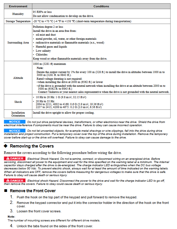
Installation direction: Priority should be given to vertical installation (to ensure heat dissipation), special models can be installed on the side (please consult the manufacturer)
Distance requirement:
Single machine: Up and down ≥ 120mm, left and right ≥ 30mm, front ≥ 50mm
Side by side installation (specific model): Drive spacing ≥ 2mm, L8-35=1 needs to be set
Environmental restrictions:
Temperature: Open type (IP20) -10~50 ℃, Closed type (UL Type 1) -10~40 ℃
Altitude: ≤ 1000m (over 1000m, capacity reduction of 1% per 100m)
Pollution level: ≤ Level 2 (no dust, oil stains, corrosive gases)
2. Electrical installation
Key terminal requirements for circuit type wiring
Main circuit power line cross-section ≥ 0.75mm ² (control circuit), tightening torque 3.6-41.5N · m R/L1/S/L2/T/L3 (input), U/T1/V/T2/W/T3 (output)
Control circuit shielded twisted pair cable, up to 3m in length, with a distance of ≥ 30cm from the power line S1-S8 (multifunctional input), A1-A3 (analog input), FM/AM (analog output)
The grounding terminal on the motor side must be grounded, and the shielding layer must be grounded at one end FG (driver grounding) and the motor casing must be grounded
Startup and parameter configuration
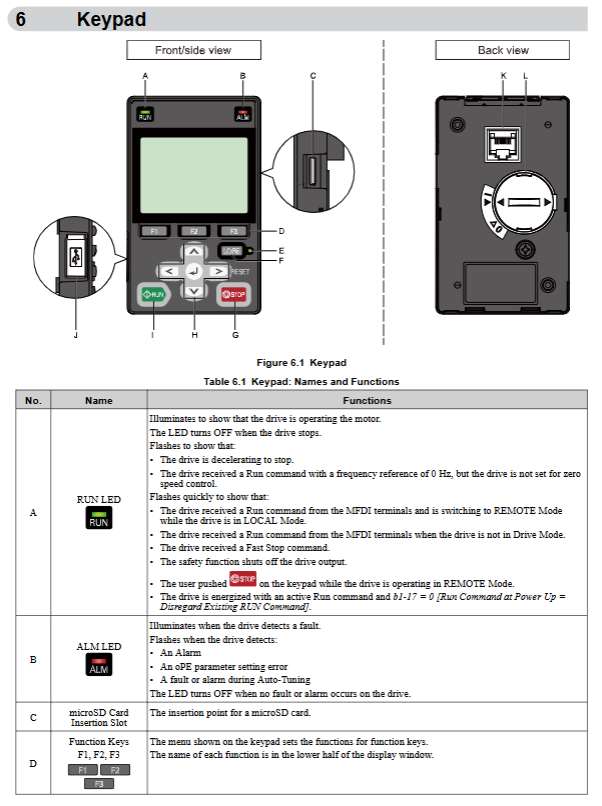
1. Keyboard operation
Core components: RUN/STOP button (local start stop), LO/RE button (local/remote switch), RESET button (fault reset)
Mode description:
LOCAL mode: keyboard controls speed and start stop
REMOTE mode: External terminal or communication control (parameter b1-01/b1-02 setting)
Display screen: Supports multiple languages (including Chinese), displaying frequency, current, and fault codes
2. Initialization process
After powering on, enter the Initial Setup interface and set the date/time (requires installation of CR2016 battery)
Run the Setup Wizard and enter the motor nameplate parameters (rated power, voltage, current, frequency)
Execute Auto Tuning:
Rotation tuning (T1-01=0): Need to be unloaded, motor speed should be above 50% of rated frequency
Static tuning (T1-01=1): Automatically calculates motor parameters without disconnecting from the load
No load test run: Confirm the motor direction and no abnormal vibration/noise
Load and run: Verify acceleration/deceleration time (C1-01/C1-02), overload capacity
3. Core parameter configuration
Parameter code, parameter name, function description, typical settings
A1-02 Control mode selection switch V/f/OLV/EZOLV 0 (V/f, general scenario)
C1-01 Acceleration Time 1 Time from 0 to maximum frequency of 10.0s (default, adjustable according to load)
C6-01 duty mode selects constant torque/variable torque switching 0 (Heavy Duty, constant torque)
E2-01 motor rated current matching motor nameplate current entered according to actual motor parameters
L1-01 motor overload protection electronic thermal protection mode 2 (constant torque 10:1 speed range)
4. Comparison of control methods
Control mode parameter setting applicable scenarios core advantages
V/f control A1-02=0 fan, pump, multi motor linkage has strong universality and does not require motor parameters
Open loop vector (OLV) A1-02=2 high-precision speed control without speed feedback, high low-speed torque
EZ vector A1-02=8 simplified settings for ordinary variable speed scenarios, no need for fine tuning
Troubleshooting
1. Common faults and solutions
Fault code, fault name, common causes, and solutions
Check the wiring for overcurrent output short circuit, heavy load, and short acceleration time at oC, reduce load, and increase C1-01
OV overvoltage deceleration time is too short, brake resistor damage increases deceleration time, replace brake resistor, activate L3-04 (stall prevention)
Overloading of oL1 motor, overload of motor, low speed to reduce load, use of forced cooling motor, correction of E2-01 parameters
Overload of oL2 drive, insufficient drive capacity, low-speed high torque replacement with large capacity models, reducing load
GF grounding fault output side grounding short circuit, motor insulation damage inspection wiring, testing motor insulation resistance (≥ 10M Ω)
STo safety torque OFF safety input terminal disconnection inspection H1/H2/HC wiring, reset safety controller
2. Fault reset process
Remove the source of the fault (such as power-off inspection of wiring, reducing load)
Waiting for the discharge of the driver capacitor (indicator light off)
Press the RESET key on the keyboard, or power off and restart
If it repeatedly occurs, check the parameter configuration or contact the manufacturer for repair
Compliance and scrapping
Compliance standards: Complies with IEC/EN 61800-5-1, UL 508C, CSA C22.2 No.100
Scrap requirements:
Separate the battery (CR2016) and microSD card and dispose of them separately according to regulations
SD cards need to be physically destroyed or data erased to prevent information leakage
Drive body is classified and recycled according to industrial waste
- YOKOGAWA
- Reliance
- ADVANCED
- SEW
- ProSoft
- WATLOW
- Kongsberg
- FANUC
- VSD
- DCS
- PLC
- man-machine
- Covid-19
- Energy and Gender
- Energy Access
- Renewable Integration
- Energy Subsidies
- Energy and Water
- Net zero emission
- Energy Security
- Critical Minerals
- A-B
- petroleum
- Mine scale
- Sewage treatment
- cement
- architecture
- Industrial information
- New energy
- Automobile market
- electricity
- Construction site
- HIMA
- ABB
- Rockwell
- Schneider Modicon
- Siemens
- xYCOM
- Yaskawa
- Woodward
- BOSCH Rexroth
- MOOG
- General Electric
- American NI
- Rolls-Royce
- CTI
- Honeywell
- EMERSON
- MAN
- GE
- TRICONEX
- Control Wave
- ALSTOM
- AMAT
- STUDER
- KONGSBERG
- MOTOROLA
- DANAHER MOTION
- Bentley
- Galil
- EATON
- MOLEX
- Triconex
- DEIF
- B&W
- ZYGO
- Aerotech
- DANFOSS
- KOLLMORGEN
- Beijer
- Endress+Hauser
- schneider
- Foxboro
- KB
- REXROTH
- YAMAHA
- Johnson
- Westinghouse
- WAGO
- TOSHIBA
- TEKTRONIX
- BENDER
- BMCM
- SMC
- HITACHI
- HIRSCHMANN
- XP POWER
- Baldor
- Meggitt
- SHINKAWA
- Other Brands
- UniOP
- KUKA
- IBA
- Beckhoff
- ADLINK
-
Beckhoff EP9224-0037 - 4-Channel Power Distribution Box EtherCAT
-
Beckhoff CX2900-0026 - Solid State Flash Memory Card 20GB CFast
-
Beckhoff BK7500 - SERCOS Interface Fieldbus Bus Coupler Terminal
-
Beckhoff Ep2328-0002 - 4-Channel Input 4-Channel Output EtherCAT Box IP67
-
Beckhoff CX1020-0111 - Controller Kit Combo Interface Modules
-
B&R X20AI2237 - X20 System Analog Input Interface Module
-
Beckhoff CP2221-0010 - Multi-Touch Built-In Panel PC Touchscreen
-
Beckhoff CX1500-M310 - Fieldbus Master Interface Module 24V
-
Beckhoff CX2100-0904 - Power Charging Module Smart UPS Extension
-
Beckhoff CP3918-0000 - Multi-Touch Control Panel 18.5-Inch Monitor
-
Beckhoff CP2915-0000 - 15-Inch Multi-Touch Built-In Control Panel
-
Beckhoff CP7037-1027 - HMI Industrial Control Panel Built-In PC
-
Beckhoff EL3152 - 2-Channel Analog Input Terminal 4-20mA EtherCAT
-
Beckhoff CP6607-0000-0020 - 5.7-Inch Built-In Panel PC HMI Touch
-
Beckhoff EJ1809-0000 - 16-Channel Digital Input Pluggable Signal Level Terminal
-
Beckhoff AM8563-0N10-0000 - Synchronous Servo Motor
-
Beckhoff AX2006-S60600-520 - Compact Servo Drive Inverter
-
Beckhoff AM8053-0K20-0000 - Servo Motor with Planetary Gearbox AG3210
-
Beckhoff AM8042-0FH1-0000 - Synchronous Servo Motor
-
Rexroth R911338600 - IndraControl V HMI Terminal Beckhoff PCI Card FC9002
-
Beckhoff AX5125-0000 - 3 Phase Industrial Servo Drive 1000Hz
-
Beckhoff EP2328-0002 - 4-Channel Digital Input 4-Channel Output EtherCAT Box
-
B&R 7CP476-02 - System 2005 RTD CPU Module 3IF681.86 Interface
-
Beckhoff AX8620-0000-0000 - Power Supply Module Axis Drive System
-
Beckhoff CX1010-0111 - PLC Module CPU Controller 24V
-
Beckhoff AM8043-0H10-0000 - Synchronous Servo Motor
-
Beckhoff C6240-1009 - Control Cabinet Industrial PC Mainframe
-
Beckhoff BX8000-0000 - Bus Terminal Controller HW 4.4 Standalone
-
Beckhoff CP7721-1089-0020 - 12.1-Inch Touch Screen HMI Panel PC
-
Beckhoff CP7132-0001 - Industrial Built-In Panel PC Screen
-
Beckhoff CP2912-0010 - Multi-Touch Built-In Control Panel Display
-
Beckhoff CP2915-0000 - 15-Inch Multi-Touch Built-In Control Panel
-
Beckhoff AM8532-1EN0-0000 - Synchronous Servo Motor
-
Beckhoff AX5203-0000 - 2-Channel Digital Compact Servo Drive
-
Beckhoff CX2020-0141 - Embedded PC Core CPU Module
-
Beckhoff CP6832-0002-0010 - Built-In Industrial Control Panel Display
-
Beckhoff CX5020-0112 - Embedded PC CPU Control Module
-
Beckhoff CX5140-0175 - 4GB Embedded PC CPU Unit 24V
-
Beckhoff EL3681-0030 - Digital Multimeter Calibration Terminal EtherCAT
-
Beckhoff CP7201-1000-0000 - Industrial PC Touch Screen HMI Monitor
-
Beckhoff CP7232-1001-0000 - Industrial Panel PC Touch Screen
-
Beckhoff C6930-1032-0040 - Control Cabinet Industrial PC System
-
Beckhoff AX5125-0000 - 3 Phase Industrial Servo Drive 1000Hz
-
Beckhoff CP3916-1424-0000 - Multi-Touch Built-In Control Panel
-
B&R 1900071142 - Lemoine Fieldbus Communication Interface Module
-
Beckhoff EL2872 - 16-Channel Ribbon Cable Digital Output Terminal
-
Beckhoff CX2030-0120 - Embedded PC CPU Base Module Controller
-
Beckhoff CP3919-0000 - 19-Inch Multi-Touch Control Panel Touchscreen
-
Beckhoff AX5101-0000-0202 - Servo Driver Compact Intelligent Drive 180V
-
Beckhoff CX5130-0135 - Embedded PC Controller Module
-
Beckhoff CP3719-1061-0010 - Multi-Touch Panel PC Outer Housing Enclosure
-
Beckhoff CP3919-1033-0000 - 19-Inch Touch Industrial Panel Keyboard
-
Beckhoff CX5020-0111 - Embedded PC PLC CPU Module
-
Beckhoff FC5102-0000 - 2-Channel CANopen PCI Control Board Card
-
Beckhoff CX9001-1101 - Embedded PC CPU Network I/O System Module
-
Beckhoff CX1100-0920 - Smart Position Sensor Interface Module
-
B&R 4P3040.01-490 - Operator Panel PLC Interface Communication Module
-
Beckhoff CP2612-0000 - Dual-Touch Built-In Panel PC HMI
-
Beckhoff CP7002-1043-0010 - Touchscreen Display HMI Panel Terminal
-
Beckhoff CX9020-0115 - Embedded PC Controller Module
-
Beckhoff CX5140-0155 - 4GB Embedded PC CPU Module Die Industry
-
B&R 7DI435.7 - System 2005 Universal Digital Input Output Module
-
Bihl+Wiedemann BWU1568 - AS-i Master to Profibus Gateway Module
-
Beckhoff C6920-0070 - Control Cabinet Industrial PC 8GB Win 10
-
B&R X20AI2322 - 2-Channel Temperature Analog Input Module
-
Beckhoff CP2912-0000 - 12-Inch Touchscreen Display Monitor Screen
-
Beckhoff CP6022-1001-0010 - 15-Inch Built-In Control Panel
-
Beckhoff AM8031-0D10-0000 - Synchronous Servo Motor
-
Beckhoff CX5010-0111 - Embedded PC Controller CPU Module
-
Beckhoff CP7232-1000-0000 - Industrial Panel PC Touch Display Screen
-
Beckhoff CP7802-0011-0000 - 15-Inch Industrial Touchscreen Control Panel
-
Beckhoff C6320 - Control Cabinet Industrial PC
-
Beckhoff CX1030-0012 - Basic CPU Module Windows CE 6.0
-
Beckhoff CP2919-0000 - Installation Multi-Touch Control Panel
-
Beckhoff CX1020-0000 - Controller Set Stack System Pack
-
B&R 3DO480.6 - System 2005 Digital Output Module
-
Beckhoff EL3101 - 1-Channel Analog Input Terminal Differential +/-10V
-
Beckhoff AX8108-0200-0000 - Axis Feed Module Servo Drive
-
Beckhoff CP7802-1241-0010 - 15-Inch Industrial Touchscreen Control Panel
-
Beckhoff FC2002-0000 - 2-Channel Lightbus Data Acquisition PCI Card
-
Beckhoff CX5120-0155 - 2GB Embedded PC Intel Atom Controller
-
Beckhoff Cx9020-0111 - 1GB Basic CPU Module Embedded PC
-
Beckhoff CP6901-0001-0000 - 12-Inch Economy Built-In Control Panel
-
Beckhoff CX9020-0111 - Embedded PC CPU Basic Module
-
Beckhoff CX5130-0100 - 4GB Embedded PC CPU Module
-
Beckhoff CP2715-0010 - Multi-Touch Built-In Panel PC
-
Beckhoff CX2033-0175 - Embedded PC CPU Module Core i7
-
Beckhoff CP7201-1000-0000 - 12-Inch Touchscreen Panel PC AMAT Green Box
-
Beckhoff EL4038 - 8-Channel Analog Output Terminal 0-10V EtherCAT
-
Beckhoff CP6802-0000-0000 - Built-In Control Panel HMI Screen
-
Beckhoff CP6500-1012-0060 - Control Cabinet PC Interface Unit
-
Beckhoff FC5202-0000 - 2-Channel DeviceNet Master PCI Interface Card
-
Beckhoff CP6606-0001-0020 - 7-Inch Economy Panel PC Touch
-
Beckhoff CP2921-0010 - Multi-Touch Integrated Control Panel Display
-
Beckhoff CP7802-0001-0010 - 15-Inch Touch Screen Control Panel HMI
-
Beckhoff C6920-0050 - Control Cabinet Industrial PC
-
Beckhoff BK9105 - EtherNet/IP Bus Coupler Network Interface
-
Beckhoff 31 Modules - Bus Terminal Slice I/O Lot Assortment
-
Beckhoff CX2020-0120 - Embedded PC Basic CPU Module 8GB CFast Card
-
Beckhoff CP7001-0000 - HMI Control Panel Touch Screen
-
B&R 7EX484.50-1 - System 2005 Controller Base Module Slots
-
Beckhoff EK1322 - 2-Port EtherCAT P Extension Feed-In Terminal
-
Beckhoff CP6606-0001-0020 - 7-Inch Single-Touch Economy Panel PC
-
Beckhoff CP6607-0001-0000 - Economy Installation Operator Panel PC 5.7-Inch
-
Beckhoff AX5103-0000-0200 - Digital Compact Servo Driver 3 Phase
-
Beckhoff CP7802-0001-0010 - 15-Inch Touch Screen Control Panel
-
Beckhoff AX8620 - Power Supply Module Axis System
-
Beckhoff CX2030-0121 - Embedded PC Controller Module
-
Beckhoff CP6606-0001-0020 - 7-Inch Economy Panel PC Touch Screen
-
Beckhoff CX2030-0121 - Embedded PC CPU Module Windows Standard 7
-
Beckhoff BX3100-0000 - PROFIBUS DP Bus Terminal Controller
-
Beckhoff CX1020-0000 - Controller Set with Power Supply Unit
-
Beckhoff EK1100 - EtherCAT Coupler Terminal Module Set
-
Beckhoff CP7002-1043-0010 - HMI Display Panel with Control Panel Bracket
-
Beckhoff AM8031-0D10-0000 - Synchronous Servo Motor
-
Beckhoff CX5130-0175 - Embedded PC 4GB RAM Controller
-
Beckhoff CX5130-0155 - Embedded PC Automation Controller
-
Beckhoff C6930-0010 - Control Cabinet Industrial PC Core Duo
-
Beckhoff CP3924-0000 - Multi-Touch Control Panel Display
-
Beckhoff AM8023-0F20-0000 - Synchronous Servo Motor
-
B&R KL3362 - Bus Terminal Thermocouple Input Module
-
Beckhoff AL2006-0000-0000 - Linear Servo Motor Three Phase
-
Beckhoff CX5140-0155 - Embedded PC CPU Controller Module
-
Beckhoff FC9002 - Ethernet PCI Network Interface Card
-
Beckhoff CP7203-0021-0040 - Built-In Panel PC 19-Inch Touch Screen
-
Beckhoff C6930-0020 - Control Cabinet Industrial PC HDD CF Card
-
Beckhoff CX2900-0033 - Memory Card CFast Storage
-
Beckhoff CP6201-0001-0020 - Built-In Panel PC Display

K-JIANG

Add: Jimei North Road, Jimei District, Xiamen, Fujian, China
Tell:+86-15305925923