
K-WANG


Woodward GS10 Gas Metering System
Woodward GS10 Gas Metering System
Application scenarios
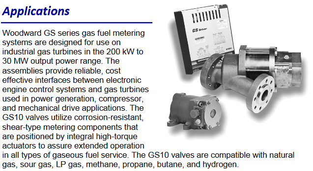
The Woodward GS series gas metering system is designed specifically for industrial gas turbines with output power ranging from 200kW to 30MW. It provides a reliable and cost-effective interface between electronic engine control systems and gas turbines in applications such as power generation, compressors, and mechanical drives. The GS10 valve is compatible with various gas fuels, such as natural gas, acidic gases, liquefied petroleum gas, methane, propane, butane, and hydrogen.
Product description
Structure and Design: GS10 adopts a rotary plate valve, integrates electric actuators and non-contact position sensors to achieve precise flow control. The use of rare earth permanent magnets in its efficient electromagnetic circuit reduces the packaging size. The integrated brushless DC actuator and valve design eliminates the backlash problem of gear motors and avoids the resolution and periodic oscillation issues of stepper motors.
Core Features
Self cleaning rotary plate valve with anti pollution properties.
Fully electric drive.
Only a single moving component.
Resistant to vibration and has a wide operating temperature range.
Quick response and high precision in flow control.
No on-site adjustment or assembly is required.
Standard 4-20mA interface with discrete fault output and shutdown function.
Some models have been certified for hazardous locations in North America.
Flow control and calibration: Gas flow control is usually achieved by accurately setting the port area of the metering valve based on assumed values of gas characteristics, pressure, and temperature. The GS10 valve is calibrated in the factory under actual flow conditions to provide accurate valve measurement area based on input signal requirements. The actual fuel flow rate depends on the valve area, gas pressure, gas temperature, and the gas itself. The fuel flow equation for the GS10 valve is located in the GS manual and available software programs, and can be used to set the GS10 valve under any specific site conditions.
Valve size: The GS10 valve is suitable for gas turbines with output power ranging from 2-15MW (depending on the characteristics and conditions of the available fuel gas). The rotary plate valve and actuator are located within a single low-carbon steel casing, with a 2-inch raised face flange gas connection and standard flange spacing. The measuring port size of GS10 valve is available in two types: 0.5 square inches (323 square millimeters) and 1.0 square inches (645 square millimeters).
Technical Parameter
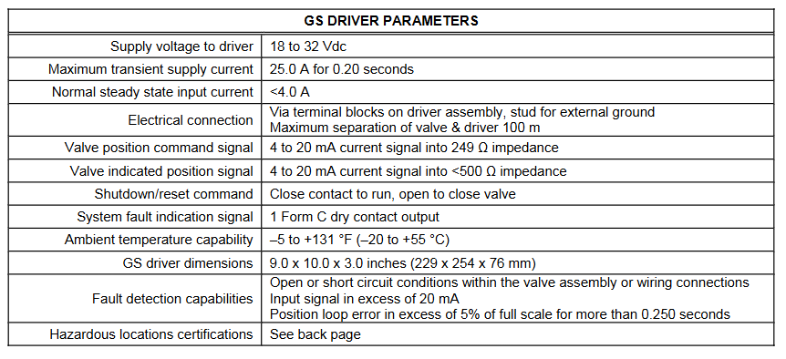
GS driver parameters
Power supply voltage: 18-32Vdc.
Maximum transient power supply current: 25.0A, lasting for 0.20 seconds.
Normal steady-state input current:<4.0A.
Electrical connection: through the wiring terminals on the driver components and external grounding poles; The maximum distance between the valve and the actuator is 100m.
Valve position command signal: 4-20mA current signal, input impedance 249 Ω.
Valve indication position signal: 4-20mA current signal, input impedance<500 Ω.
Shutdown/reset command: Close the contact to operate, open to close the valve.
System fault indication signal: 1 set of C-type dry contact output.
Environmental temperature capability: -5 to+131 ° F (-20 to+55 ° C).
GS drive size: 9.0 x 10.0 x 3.0 inches (229 x 254 x 76mm).
Fault detection capability: open or short circuits in valve components or wiring connections; The input signal exceeds 20mA; the position loop error exceeds 5% of the full range and lasts for more than 0.250 seconds.
Dangerous place certification: see next page.
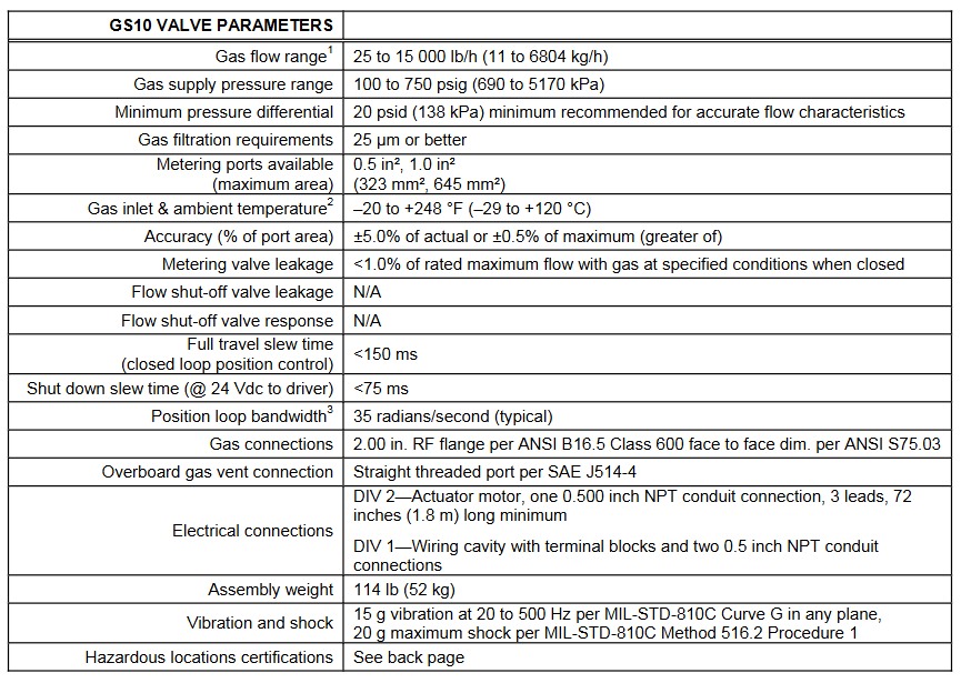
GS10 valve parameters
Gas flow range: 25-15000lb/h (11-6804kg/h).
Gas supply pressure range: 100-750PSI (690-5170kPa).
Minimum pressure difference: To ensure accurate flow characteristics, it is recommended to have a minimum of 20 psid (138 kPa).
Gas filtration requirements: 25 μ m or higher precision.
Available metering ports (maximum area): 0.5 square inches, 1.0 square inches (323 square millimeters, 645 square millimeters).
Gas inlet and ambient temperature: -20 to+248 ° F (-29 to+120 ° C) (note: dry gas is required when the temperature is below 0 ° C (32 ° F)).
Accuracy (percentage of port area): ± 5.0% of actual value or ± 0.5% of maximum value (whichever is greater).
Leakage of metering valve: Under specified conditions, the leakage amount when the gas is closed is less than 1.0% of the rated maximum flow rate.
Leakage of flow stop valve: Not applicable.
Flow stop valve response: Not applicable.
Full travel conversion time (closed-loop position control):<150ms.
Shutdown conversion time (when the driver voltage is 24Vdc):<75ms.
Position loop bandwidth: 35 radians per second (typical value) (note: the system dynamics are roughly second-order. The bandwidth is determined by the amplitude response at -6dB, and the GS driver voltage is 24Vdc).
Gas connection: 2.00 inch RF flange, compliant with ANSI B16.5 Class 600; Face to face dimensions comply with ANSI S75.03.
External gas emission connection: straight threaded port in accordance with SAE J514-4.
Electrical connection: Zone 2- actuator motor, one 0.500 inch NPT conduit connection, 3 wires, minimum 72 inches (1.8m) long; Zone 1- Wiring chamber with terminal blocks and two 0.5-inch NPT conduit connections.
Component weight: 114lb (52kg).
Vibration and impact: 15g vibration at 20-500Hz on any plane, in accordance with MIL-STD-810C curve G; maximum impact of 20g, in accordance with MIL-STD-810C method 516.2 procedure 1.
Dangerous place certification: see next page.
Regulatory compliance
European compliance (CE marking): only applicable to units with CE marking.
EMC Directive (GS Drive): Complies with Council Directive 89/336/EEC of May 3, 1989 on the harmonization of the laws of Member States relating to electromagnetic compatibility.
ATEX - Directive on Potential Explosive Atmospheres (GS Drivers): Complies with Council Directive 94/9/EEC of March 23, 1994 on the harmonization of the laws of Member States relating to equipment and protective systems used in potentially explosive atmospheres. LCIE 01. ATEX.6012 X Zone 2, Class 3, Class II Group G, EEx nC/L IIC T4。 Special conditions for safe use: The GS driver must be installed in an IP54 rated enclosure that meets the requirements of European standard EN 50021 (1999) and must be connected to the GS10 valve/actuator.
North American Compliance: Only applicable to units with UL or CSA agency markings.
GS10 valve CSA: CSA certified, suitable for Class I, Zone 1, Groups C and D, T3C at ambient temperature of 120 ° C. Can be used in Canada and the United States.
GS driver UL: UL certified, suitable for Class I, Zone 2, Groups A, B, C, and D, with an ambient temperature of 55 ° C. Can be used in Canada and the United States. Certified by CSA, suitable for Class I Zone 1, Groups A, B, C, and D, T4A at an ambient temperature of 55 ° C. Can be used in Canada and the United States.
- YOKOGAWA
- Reliance
- ADVANCED
- SEW
- ProSoft
- WATLOW
- Kongsberg
- FANUC
- VSD
- DCS
- PLC
- man-machine
- Covid-19
- Energy and Gender
- Energy Access
- Renewable Integration
- Energy Subsidies
- Energy and Water
- Net zero emission
- Energy Security
- Critical Minerals
- A-B
- petroleum
- Mine scale
- Sewage treatment
- cement
- architecture
- Industrial information
- New energy
- Automobile market
- electricity
- Construction site
- HIMA
- ABB
- Rockwell
- Schneider Modicon
- Siemens
- xYCOM
- Yaskawa
- Woodward
- BOSCH Rexroth
- MOOG
- General Electric
- American NI
- Rolls-Royce
- CTI
- Honeywell
- EMERSON
- MAN
- GE
- TRICONEX
- Control Wave
- ALSTOM
- AMAT
- STUDER
- KONGSBERG
- MOTOROLA
- DANAHER MOTION
- Bentley
- Galil
- EATON
- MOLEX
- Triconex
- DEIF
- B&W
- ZYGO
- Aerotech
- DANFOSS
- KOLLMORGEN
- Beijer
- Endress+Hauser
- schneider
- Foxboro
- KB
- REXROTH
- YAMAHA
- Johnson
- Westinghouse
- WAGO
- TOSHIBA
- TEKTRONIX
- BENDER
- BMCM
- SMC
- HITACHI
- HIRSCHMANN
- XP POWER
- Baldor
- Meggitt
- SHINKAWA
- Other Brands
- UniOP
- KUKA
- IBA
- Beckhoff
- ADLINK
-
Beckhoff EP9224-0037 - 4-Channel Power Distribution Box EtherCAT
-
Beckhoff CX2900-0026 - Solid State Flash Memory Card 20GB CFast
-
Beckhoff BK7500 - SERCOS Interface Fieldbus Bus Coupler Terminal
-
Beckhoff Ep2328-0002 - 4-Channel Input 4-Channel Output EtherCAT Box IP67
-
Beckhoff CX1020-0111 - Controller Kit Combo Interface Modules
-
B&R X20AI2237 - X20 System Analog Input Interface Module
-
Beckhoff CP2221-0010 - Multi-Touch Built-In Panel PC Touchscreen
-
Beckhoff CX1500-M310 - Fieldbus Master Interface Module 24V
-
Beckhoff CX2100-0904 - Power Charging Module Smart UPS Extension
-
Beckhoff CP3918-0000 - Multi-Touch Control Panel 18.5-Inch Monitor
-
Beckhoff CP2915-0000 - 15-Inch Multi-Touch Built-In Control Panel
-
Beckhoff CP7037-1027 - HMI Industrial Control Panel Built-In PC
-
Beckhoff EL3152 - 2-Channel Analog Input Terminal 4-20mA EtherCAT
-
Beckhoff CP6607-0000-0020 - 5.7-Inch Built-In Panel PC HMI Touch
-
Beckhoff EJ1809-0000 - 16-Channel Digital Input Pluggable Signal Level Terminal
-
Beckhoff AM8563-0N10-0000 - Synchronous Servo Motor
-
Beckhoff AX2006-S60600-520 - Compact Servo Drive Inverter
-
Beckhoff AM8053-0K20-0000 - Servo Motor with Planetary Gearbox AG3210
-
Beckhoff AM8042-0FH1-0000 - Synchronous Servo Motor
-
Rexroth R911338600 - IndraControl V HMI Terminal Beckhoff PCI Card FC9002
-
Beckhoff AX5125-0000 - 3 Phase Industrial Servo Drive 1000Hz
-
Beckhoff EP2328-0002 - 4-Channel Digital Input 4-Channel Output EtherCAT Box
-
B&R 7CP476-02 - System 2005 RTD CPU Module 3IF681.86 Interface
-
Beckhoff AX8620-0000-0000 - Power Supply Module Axis Drive System
-
Beckhoff CX1010-0111 - PLC Module CPU Controller 24V
-
Beckhoff AM8043-0H10-0000 - Synchronous Servo Motor
-
Beckhoff C6240-1009 - Control Cabinet Industrial PC Mainframe
-
Beckhoff BX8000-0000 - Bus Terminal Controller HW 4.4 Standalone
-
Beckhoff CP7721-1089-0020 - 12.1-Inch Touch Screen HMI Panel PC
-
Beckhoff CP7132-0001 - Industrial Built-In Panel PC Screen
-
Beckhoff CP2912-0010 - Multi-Touch Built-In Control Panel Display
-
Beckhoff CP2915-0000 - 15-Inch Multi-Touch Built-In Control Panel
-
Beckhoff AM8532-1EN0-0000 - Synchronous Servo Motor
-
Beckhoff AX5203-0000 - 2-Channel Digital Compact Servo Drive
-
Beckhoff CX2020-0141 - Embedded PC Core CPU Module
-
Beckhoff CP6832-0002-0010 - Built-In Industrial Control Panel Display
-
Beckhoff CX5020-0112 - Embedded PC CPU Control Module
-
Beckhoff CX5140-0175 - 4GB Embedded PC CPU Unit 24V
-
Beckhoff EL3681-0030 - Digital Multimeter Calibration Terminal EtherCAT
-
Beckhoff CP7201-1000-0000 - Industrial PC Touch Screen HMI Monitor
-
Beckhoff CP7232-1001-0000 - Industrial Panel PC Touch Screen
-
Beckhoff C6930-1032-0040 - Control Cabinet Industrial PC System
-
Beckhoff AX5125-0000 - 3 Phase Industrial Servo Drive 1000Hz
-
Beckhoff CP3916-1424-0000 - Multi-Touch Built-In Control Panel
-
B&R 1900071142 - Lemoine Fieldbus Communication Interface Module
-
Beckhoff EL2872 - 16-Channel Ribbon Cable Digital Output Terminal
-
Beckhoff CX2030-0120 - Embedded PC CPU Base Module Controller
-
Beckhoff CP3919-0000 - 19-Inch Multi-Touch Control Panel Touchscreen
-
Beckhoff AX5101-0000-0202 - Servo Driver Compact Intelligent Drive 180V
-
Beckhoff CX5130-0135 - Embedded PC Controller Module
-
Beckhoff CP3719-1061-0010 - Multi-Touch Panel PC Outer Housing Enclosure
-
Beckhoff CP3919-1033-0000 - 19-Inch Touch Industrial Panel Keyboard
-
Beckhoff CX5020-0111 - Embedded PC PLC CPU Module
-
Beckhoff FC5102-0000 - 2-Channel CANopen PCI Control Board Card
-
Beckhoff CX9001-1101 - Embedded PC CPU Network I/O System Module
-
Beckhoff CX1100-0920 - Smart Position Sensor Interface Module
-
B&R 4P3040.01-490 - Operator Panel PLC Interface Communication Module
-
Beckhoff CP2612-0000 - Dual-Touch Built-In Panel PC HMI
-
Beckhoff CP7002-1043-0010 - Touchscreen Display HMI Panel Terminal
-
Beckhoff CX9020-0115 - Embedded PC Controller Module
-
Beckhoff CX5140-0155 - 4GB Embedded PC CPU Module Die Industry
-
B&R 7DI435.7 - System 2005 Universal Digital Input Output Module
-
Bihl+Wiedemann BWU1568 - AS-i Master to Profibus Gateway Module
-
Beckhoff C6920-0070 - Control Cabinet Industrial PC 8GB Win 10
-
B&R X20AI2322 - 2-Channel Temperature Analog Input Module
-
Beckhoff CP2912-0000 - 12-Inch Touchscreen Display Monitor Screen
-
Beckhoff CP6022-1001-0010 - 15-Inch Built-In Control Panel
-
Beckhoff AM8031-0D10-0000 - Synchronous Servo Motor
-
Beckhoff CX5010-0111 - Embedded PC Controller CPU Module
-
Beckhoff CP7232-1000-0000 - Industrial Panel PC Touch Display Screen
-
Beckhoff CP7802-0011-0000 - 15-Inch Industrial Touchscreen Control Panel
-
Beckhoff C6320 - Control Cabinet Industrial PC
-
Beckhoff CX1030-0012 - Basic CPU Module Windows CE 6.0
-
Beckhoff CP2919-0000 - Installation Multi-Touch Control Panel
-
Beckhoff CX1020-0000 - Controller Set Stack System Pack
-
B&R 3DO480.6 - System 2005 Digital Output Module
-
Beckhoff EL3101 - 1-Channel Analog Input Terminal Differential +/-10V
-
Beckhoff AX8108-0200-0000 - Axis Feed Module Servo Drive
-
Beckhoff CP7802-1241-0010 - 15-Inch Industrial Touchscreen Control Panel
-
Beckhoff FC2002-0000 - 2-Channel Lightbus Data Acquisition PCI Card
-
Beckhoff CX5120-0155 - 2GB Embedded PC Intel Atom Controller
-
Beckhoff Cx9020-0111 - 1GB Basic CPU Module Embedded PC
-
Beckhoff CP6901-0001-0000 - 12-Inch Economy Built-In Control Panel
-
Beckhoff CX9020-0111 - Embedded PC CPU Basic Module
-
Beckhoff CX5130-0100 - 4GB Embedded PC CPU Module
-
Beckhoff CP2715-0010 - Multi-Touch Built-In Panel PC
-
Beckhoff CX2033-0175 - Embedded PC CPU Module Core i7
-
Beckhoff CP7201-1000-0000 - 12-Inch Touchscreen Panel PC AMAT Green Box
-
Beckhoff EL4038 - 8-Channel Analog Output Terminal 0-10V EtherCAT
-
Beckhoff CP6802-0000-0000 - Built-In Control Panel HMI Screen
-
Beckhoff CP6500-1012-0060 - Control Cabinet PC Interface Unit
-
Beckhoff FC5202-0000 - 2-Channel DeviceNet Master PCI Interface Card
-
Beckhoff CP6606-0001-0020 - 7-Inch Economy Panel PC Touch
-
Beckhoff CP2921-0010 - Multi-Touch Integrated Control Panel Display
-
Beckhoff CP7802-0001-0010 - 15-Inch Touch Screen Control Panel HMI
-
Beckhoff C6920-0050 - Control Cabinet Industrial PC
-
Beckhoff BK9105 - EtherNet/IP Bus Coupler Network Interface
-
Beckhoff 31 Modules - Bus Terminal Slice I/O Lot Assortment
-
Beckhoff CX2020-0120 - Embedded PC Basic CPU Module 8GB CFast Card
-
Beckhoff CP7001-0000 - HMI Control Panel Touch Screen
-
B&R 7EX484.50-1 - System 2005 Controller Base Module Slots
-
Beckhoff EK1322 - 2-Port EtherCAT P Extension Feed-In Terminal
-
Beckhoff CP6606-0001-0020 - 7-Inch Single-Touch Economy Panel PC
-
Beckhoff CP6607-0001-0000 - Economy Installation Operator Panel PC 5.7-Inch
-
Beckhoff AX5103-0000-0200 - Digital Compact Servo Driver 3 Phase
-
Beckhoff CP7802-0001-0010 - 15-Inch Touch Screen Control Panel
-
Beckhoff AX8620 - Power Supply Module Axis System
-
Beckhoff CX2030-0121 - Embedded PC Controller Module
-
Beckhoff CP6606-0001-0020 - 7-Inch Economy Panel PC Touch Screen
-
Beckhoff CX2030-0121 - Embedded PC CPU Module Windows Standard 7
-
Beckhoff BX3100-0000 - PROFIBUS DP Bus Terminal Controller
-
Beckhoff CX1020-0000 - Controller Set with Power Supply Unit
-
Beckhoff EK1100 - EtherCAT Coupler Terminal Module Set
-
Beckhoff CP7002-1043-0010 - HMI Display Panel with Control Panel Bracket
-
Beckhoff AM8031-0D10-0000 - Synchronous Servo Motor
-
Beckhoff CX5130-0175 - Embedded PC 4GB RAM Controller
-
Beckhoff CX5130-0155 - Embedded PC Automation Controller
-
Beckhoff C6930-0010 - Control Cabinet Industrial PC Core Duo
-
Beckhoff CP3924-0000 - Multi-Touch Control Panel Display
-
Beckhoff AM8023-0F20-0000 - Synchronous Servo Motor
-
B&R KL3362 - Bus Terminal Thermocouple Input Module
-
Beckhoff AL2006-0000-0000 - Linear Servo Motor Three Phase
-
Beckhoff CX5140-0155 - Embedded PC CPU Controller Module
-
Beckhoff FC9002 - Ethernet PCI Network Interface Card
-
Beckhoff CP7203-0021-0040 - Built-In Panel PC 19-Inch Touch Screen
-
Beckhoff C6930-0020 - Control Cabinet Industrial PC HDD CF Card
-
Beckhoff CX2900-0033 - Memory Card CFast Storage
-
Beckhoff CP6201-0001-0020 - Built-In Panel PC Display

K-JIANG

Add: Jimei North Road, Jimei District, Xiamen, Fujian, China
Tell:+86-15305925923