
K-WANG


Emerson HART High Performance Analog Input Module
Emerson HART High Performance Analog Input Module
Module Overview
The HART (Highway Addressable Remote Transformer) high-performance analog input module is a standard Ovation I/O module, updated to the 3rd edition of the Ovation I/O Reference Manual on March 3, 2003, and should be placed between Chapters 14 and 15. It provides 8 globally isolated 4-20mA analog inputs, equipped with HART transceivers, each of which is connected to a dedicated UART through optical isolation communication to maximize HART communication. This module can communicate with HART devices and support "smart" field devices. The analog 4-20mA signal, digital communication, and sometimes power supply of such devices can coexist on the same pair of wires.
Module group
Electronic module: There is only one set of 5X00106G01, which can connect 8 current loop signals with an input range of 4-20mA.
Personality module: There is only one set of 5X00109G01, which includes a printed circuit board component with 8 fuse inputs and user accessible jumper wires. It can be configured with transmitters for on-site or local power supply channels one by one.
Power supply
The logic circuit is powered by a standard+24V Ovation main power supply.
The on-site power supply is provided by a 24V auxiliary power supply, including all 4-20mA loop power supplies, A/D converters, and other output channel components. It can be a standard 24V Ovation auxiliary power supply or an external power supply provided by the user.
It is recommended to use the Ovation cabinet's auxiliary+24V DC power supply. If an external auxiliary power supply is used, its noise should be ≤ 1.2Vrms.
All modules using auxiliary power sources (including HART modules) must use shielded I/O cables to suppress coupling noise and transients.
Technical specifications
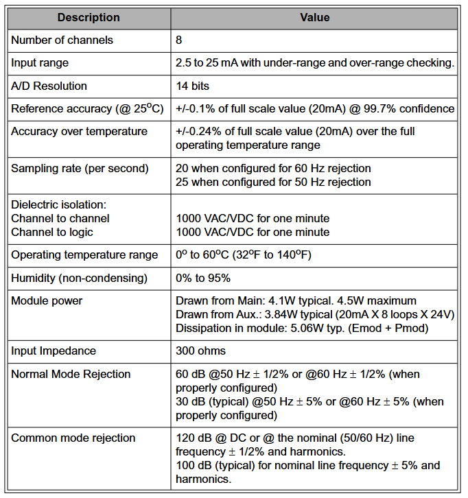
Number of channels: 8
Input range: 2.5 to 25mA, with under range and over range checks
A/D resolution: 14 bits
Reference accuracy (@ 25 ° C): ± 0.1% full-scale value (20mA), confidence level 99.7%
Full operating temperature range accuracy: ± 0.24% full-scale value (20mA)
Sampling rate (per second): 20 times when configured for 60Hz suppression; 25 times when configured for 50Hz suppression
Dielectric isolation between channels: 1000VAC/VDC, lasting for 1 minute; Channel and logic: 1000VAC/VDC, lasting for 1 minute
Working temperature range: 0 ° C to 60 ° C (32 ° F to 140 ° F)
Humidity (non condensing): 0% to 95%
Module power consumption: main power supply: typical 4.1W, maximum 4.5W; auxiliary power supply: typical 3.84W (20mA x 8 loops x 24V); Module Dissection: Typical 5.06W (Emod+Pmod)
Input impedance: 300 ohms
Common mode rejection ratio: 120dB for DC or nominal (50/60Hz) line frequency ± 1/2% and harmonics; typical 100dB for nominal line frequency ± 5% and harmonics
Personalized module and wiring information
Personality module: Each channel has a 1/20A fuse for loop protection, and each channel has a pair of user accessible jumpers that can be configured as locally or on-site powered transmitters according to the channel. The fuses and jumpers can be accessed from the top of the module.
Wiring information: There is a simplified wiring diagram label on the side of the personality module, indicating the connection method between the on-site wiring and the base unit terminal block. Each channel has two wiring configurations (depending on the transmitter configuration for local or on-site power supply), and relevant abbreviations are defined.
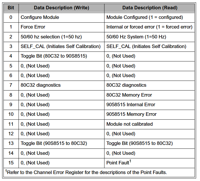
Register Mapping and Function
The module has 16 direct registers, including indirect memory indexes, analog input channel data, calibration registers, channel error bits, module configuration/status registers, HART enable registers, etc. Among them, module status register # 13 (hexadecimal D) can be read through the operator station's point information window, and word address # 12 (hexadecimal C) is used to report errors in 8 input channels.
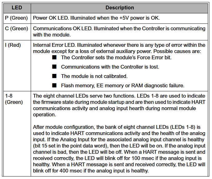
Diagnostic LED
P (green): LED with normal power supply, lights up when the+5V power supply is normal.
C (green): Communication is normal LED, which lights up when the controller communicates with the module.
I (red): Internal error LED, which lights up when any error occurs inside the module (except for loss of external auxiliary power supply). Possible reasons include forced error bits in the controller setting module, loss of communication with the controller, etc.
1-8 (green): Eight channel LEDs indicate firmware status during module startup and HART communication activity and analog input health during normal operation.
Other
The requirements for on-site wiring cables can refer to the HART FSK physical layer specification (HFC_SPEC-54).
The point data register is located at positions 2-9, corresponding to analog input points 1-8 respectively.
The HAI, HAO, and IAH modules are capable of retrieving additional variables from field devices, known as "multivariate", including PV (primary variable), SV (secondary variable), TV (tertiary variable), and QV (quarterly variable).
- YOKOGAWA
- Reliance
- ADVANCED
- SEW
- ProSoft
- WATLOW
- Kongsberg
- FANUC
- VSD
- DCS
- PLC
- man-machine
- Covid-19
- Energy and Gender
- Energy Access
- Renewable Integration
- Energy Subsidies
- Energy and Water
- Net zero emission
- Energy Security
- Critical Minerals
- A-B
- petroleum
- Mine scale
- Sewage treatment
- cement
- architecture
- Industrial information
- New energy
- Automobile market
- electricity
- Construction site
- HIMA
- ABB
- Rockwell
- Schneider Modicon
- Siemens
- xYCOM
- Yaskawa
- Woodward
- BOSCH Rexroth
- MOOG
- General Electric
- American NI
- Rolls-Royce
- CTI
- Honeywell
- EMERSON
- MAN
- GE
- TRICONEX
- Control Wave
- ALSTOM
- AMAT
- STUDER
- KONGSBERG
- MOTOROLA
- DANAHER MOTION
- Bentley
- Galil
- EATON
- MOLEX
- Triconex
- DEIF
- B&W
- ZYGO
- Aerotech
- DANFOSS
- KOLLMORGEN
- Beijer
- Endress+Hauser
- schneider
- Foxboro
- KB
- REXROTH
- YAMAHA
- Johnson
- Westinghouse
- WAGO
- TOSHIBA
- TEKTRONIX
- BENDER
- BMCM
- SMC
- HITACHI
- HIRSCHMANN
- XP POWER
- Baldor
- Meggitt
- SHINKAWA
- Other Brands
- UniOP
- KUKA
- IBA
-
Woodward 8272-796 - Real Power Sensor Module 115/230v-ac
-
Woodward 5463-873 - NetCon Output Module
-
Woodward 8271-567 - Load Sensor Module 120/208v-ac
-
Woodward Type UG-8 P/N 8522-300 EG - Governor R.P.M 1075-1650 With Motor Groschopp
-
WOODWARD 9905-971 REV J - LINKNET 16 CHANNEL DISCRETE INPUT MODULE
-
WOODWARD 8280-3014 - 723 PLUS DIGITAL CONTROL REV NEW
-
Woodward 505DE - Digital Control System
-
Woodward 5453-750 - Ethernet Interface FTM
-
Woodward 9907-018 Rev H - 2301A Load Sharing & Speed Control
-
WOODWARD 5420-1080 V4.3 - BOARD-PPA WITHBOX
-
Woodward b 8271-347SP - 2301 speed control
-
Woodward 9905-795 Rev B - Digital Synchronizer and Load Control
-
Woodward 9905-377 Rev. A - 2301A Load Sharing and Speed Control
-
WOODWARD 8272-582 - Generator speed control module
-
WOODWARD 9907-247 REV K - 828 DIGITAL CONTROL UNIT
-
WOODWARD 5466-353 REV C - NETCON MAIN CHASSIS TRANSCEIVER
-
Woodward Type UG-8 P/N 8524-708 - Governor 760-1560 Governor R.P.M
-
WOODWARD 9907-247 REV K - 828 DIGITAL CONTROL UNIT
-
WOODWARD 8440-1831 REV. H - EASYGEN3000 3200-5 - WITHOUT ACCESSORIES
-
WOODWARD 8444-1002 REV G - UMT1 MEASURING TRANSDUCERS
-
Woodward 5410-312C - Digital Marine Control Printed Circuit Board
-
Woodward 9905-799 REV F - Digital Synchronizer & Load Control , V#456
-
Woodward 9907-014 - 2301A for controller
-
Woodward Type UG-8 P/N B522-446 - Governor R.P.M 500-1200
-
WOODWARD 8272-221 REV.B - DIGITAL REFERENCE UNIT
-
Woodward 8901-037 - Booster Servomotor Single
-
WOODWARD 8444-1019 REV G - UMT 1 MEASURING TRANSDUCER
-
WOODWARD 1767-367 Z21 WK 0920702 - GOVERNOR MOTOR 2700 RPM KM 58-20 K 230V
-
WOODWARD 9905-972 Rev:G - LINKNET 6 CHANNEL 4-20mA OutPut
-
Woodward E8250-501 - Actuator Governor
-
LTI Drives CDF30.002.C0.7 Compact Servo Controller 08685963 DC 24V Industrial Module
-
LUST LTI Drives CDB32.008.W2.4.BR.PC1 Servo Drive Industrial Motion System
-
LUST LTI Drives CDB34.003.C2.4.PC1.H15 Servo Motor Driver Industrial Control Unit
-
LUST LTI Drives CDA32.004.C1.4.H08.B0 Servo Drive Mat. 3084456 Industrial Control
-
LUST LTI Drives CDE34.005.W2.2 Industrial Servo Drive Motion Control Unit
-
LUST LTI Drives CDA34.006.W3.0 Servo Drive Software V3.70-04 Industrial Controller
-
LTI Drives CDB32.004.C2.4.SH Servo Drive Compact Motion Controller
-
Woodward 9905-373 - Digital Synchronizer And Load Controller
-
WOODWARD MAGNETIC PICKUPS - Sensor
-
WOODWARD GCP-30 - Steuertafel for Industrial Regulator Genset Control Package
-
WOODWARD GOVERNOR 9907-1183 REV A - 505 ENHANCED TURBINE CONTROL
-
WOODWARD 9907-173 REV B - Module Load Sharing 120 Volt
-
WOODWARD 9907-014 - 2301A controller
-
Woodward 9905-029 - SPM-A Synchronizer Module Rev C
-
WOODWARD 8440-1799 EASYGEN-350 REV B - Genset Controller
-
WOODWARD 5466-258 REV M - SIMPLEX DISCRETE I/O MODULE
-
Woodward 8440-1884 C - Controller Easygen 2500-5
-
Woodward 8441-1153 - Monitoring Unit 250VAC
-
WOODWARD 8406-120 REV G - EGCP-2 DIGITAL CONTROL
-
Woodward 8273-584 - Atlas-ii Digital Control
-
Woodward 8272-582 - APM Motor Control 8272582
-
Woodward 9905-377 Rev. A - 2301A Load Sharing and Speed Control
-
WOODWARD 8272-517 - Pm Motor Control
-
WOODWARD 9905-797 REV.B - DIGITAL SYNCHRONIZER AND LOAD CONTROL DSLC-D
-
WOODWARD 8272-582 - APM MOTOR CONTROL
-
Woodward Seg FP2-8-24 - Emergency Power Telecommunications Module NP2
-
WOODWARD 2001-12E2U1B1S1A - Fuel Shut Off Valve Stop Solenoid Valve 2000-4505
-
Woodward 8440-1884 K - Genset Controller Easygen-2500-5
-
Woodward 9905-760 - Linknet Termination Module
-
Woodward 8404-009 - Proact Digital Plus Front Panel Rev. H
-
Woodward 8271-651 - Digital Speed Reference
-
Woodward 3077-474C - 8605895 5501-031 D Circuit Module
-
WOODWARD 5466-257 REV.-C - NETCON 5000 MODEL REMOTE TRANSCEIVER I/O MODULE
-
Woodward 8273-101 Rev: A - 2301D Digital Load Sharing and Speed Control
-
WOODWARD 8272-799 - 2301A SPEED CONTROL WITH REMOTE REFERENCE REV:C
-
Woodward 8272-517 - PM Motor Control
-
Woodward 8290-048 8290048 Rev. F - Generator Load Sensor
-
woodward 8273-1012 rev c - 2301e Load Sharing and Speed Control
-
WOODWARD 9905-797 - DIGITAL SYNCHRONIZER AND LOAD CONTROL FOR 3 PHASE GENERATORS
-
WOODWARD 8280-3014 - 723 PLUS DIGITAL CONTROL REV NEW
-
WOODWARD 8440-1884 REV G - GENSET CONTROLLER EASYGEN-2500-5/P1
-
Woodward 8272-683 K - Digital Reference
-
WOODWARD 9907-014 - SPEED CONTROL 2301A REV H
-
Woodward Type UG-8 P/N 037260 - Governor R.P.M 1075-1650 Motor KM58-20
-
WOODWARD 9905-970 - LINKNET 6 CHANNEL 100 OHM RTD Rev:J
-
Woodward 9907-1183 Rev C - Steam Turbine Digital SCREEN 505E Turbine Control
-
Woodward 8440-1614 - GCP-30 Genset Control Package, Rev: F, Type 1, E231544
-
Woodward DC11006-304-024 - ACTUOTOR DYNA ACTUATOR - BARBER-COLMAN
-
Woodward 9905-971 - LINKNET 6 CHANNEL 100 OHM RTD Rev:K
-
Woodward DYNK-10249 - Actuator Controller Kit - DYNA 2000
-
Woodward LR21035 - MFR1 MULTI FUNCTION RELAY REV F
-
Woodward 8440-1831 - EASYGEN 3200-5 P/N: REV. G Gererator Controller
-
Woodward 8272-516 - PM MOTOR CONTROL REV J
-
Woodward 8440-2080 - EASYGEN 2000 genset controller EASYGEN-2300-5/P1
-
Woodward 505DE - Digital Control System
-
Woodward 701 - Digital Speed Control 18-40 VDC 4-20 MA
-
Woodward 8440-1799 - EASYGEN-350 REV B
-
Woodward 8272-582 - Apm Motor Control 100-220v AC/DC
-
Woodward 5501-031 D - 3077-474C 8605895 Circuit Module
-
Woodward XD1-T - XD1T55SAT TRANSFORMER DIFFERENTIAL PROTECTION RELAY
-
Woodward 8272-517 - PM Motor Control 220vac
-
Woodward 8934-658 - Repair Kit UG8D Governor
-
Woodward 5437 18 - module netcon derivative analog rev.A
-
Woodward 8272-171 A - Pm Motor Control
-
Woodward MRN3-1/2 - SEG mains uncoupling relay MRN314D mains decoupling relay
-
Woodward 9905-373 - Digital Synchronizer and Load Control 18-40 VDC Rev P
-
Woodward 5431-640 C - Dual Dynamics 1000 Series Speed Control Module
-
Woodward 5501-031 D - 3077-474C 8605895 Circuit Module
-
Woodward 9907-247 - 828 DIGITAL CONTROL
-
Woodward 8440-1855-G - EASYGEN-2200-5 /P1 12/24VDC GENSET CONTROLLER
-
Woodward NC3-2-8 (NO) - GENERATOR CONTROLLER
-
Woodward 8271-467 K - 2301 LOAD SHARING AND SPEED CONTROL PART NO:
-
Woodward 8440-2177 A - SPM-D2-10 Digital Synchronising Controller
-
Woodward LXMG1614E-14-11 - CCFL and UV Lamps Inverter Module
-
Woodward 8270-990 - signal converter
-
Woodward 9905-068 - LOW VOLTAGE 2301A LOAD SHARING & SPEED CONTOL P/N:
-
Woodward 8901-051 - BOOSTER SERVOMOTOR, SINGLE CYLINDER, 2:1
-
Woodward 8444-1024 D - MWS4-55M CONTROL MODULE UNIT
-
Woodward 5448-914 - GCP-20 Genset Control GCP-20 REV D P/n:
-
Danfoss BHA-1 018-1942 - Hydraulic Actuator
-
Woodward 9905-001 L - SPM-A SYNCHRONIZER
-
Woodward 5464-850 - Module
-
Woodward 5501-371 - Micronet Simplex Mpu Aio Rev C
-
Woodward 8272-132 B - POWER SENSOR
-
Woodward 9907-028 - SPM-A Synchronizer
-
Woodward SA-3678-AM-2 - Overspeed Electric Governor, Model ESSE2-AM
-
Woodward E8250-502 - GOVERNOR ACTUATOR
-
Woodward 8440-1884 J - Controller EASYGEN-2500-5
-
Woodward 5441-693 - DIGITAL I/O MODULE -MISSING PART
-
Woodward SA-4450 - Speed Controller APECS 3100 For Magnetic Pickup
-
Woodward 9903-466 - 701 DIGITAL SPEED CONTROL REV G
-
Woodward 1765-843 - Governor Speed Adjusting Motor P/N Type: SMM40 220V AC 50/60Hz
-
Woodward 9905-760 - Linknet Termination Module
-
Woodward 9907-247 - 828 DIGITAL CONTROL UNIT REV K
-
Woodward 5484-721 - motor
-
Woodward 8440-1734 - MFR-2 Rev.A Multi Function Relay MFR-2
-
Woodward CSC3SUWA - Controller
-
Woodward 8440-1667 - REV B SPM-D1010B/XN

K-JIANG

Add: Jimei North Road, Jimei District, Xiamen, Fujian, China
Tell:+86-15305925923