
K-WANG


Horner APG HE693CALKIT simulation module
Horner APG HE693CALKIT calibration software is a computer program designed to support on-site and factory calibration of specific Horner APG simulation modules.
(2) Package composition
Each set includes: a floppy disk with calibration software, an RS-232 9-pin serial cable, a TTL to RS-232 converter, and an RS-232 ribbon cable with a 10 pin plug.
(3) Software operation requirements
Operating environment: Requires running on an IBM or compatible computer using DOS 3.1 or higher.
Hardware requirements: A text display is required and a serial port (COM1 or COM2) is used. The program defaults to using COM1.
(4) Module connection and preparation
The simulation module needs to be connected to the selected serial port on the computer through an RS-232 cable, combined with a TTL-to-RS-232 converter or an RS-232 ribbon cable with a 10 pin plug (depending on the simulation module to be calibrated).
The module does not need to be configured in the PLC, but appropriate power must be provided for the bus pins of the module.
Horner APG HE693CALKIT simulation module
Product Introduction
(1) Product Features
Horner APG HE693CALKIT calibration software is a computer program designed to support on-site and factory calibration of specific Horner APG simulation modules.
(2) Package composition
Each set includes: a floppy disk with calibration software, an RS-232 9-pin serial cable, a TTL to RS-232 converter, and an RS-232 ribbon cable with a 10 pin plug.
(3) Software operation requirements
Operating environment: Requires running on an IBM or compatible computer using DOS 3.1 or higher.
Hardware requirements: A text display is required and a serial port (COM1 or COM2) is used. The program defaults to using COM1.
(4) Module connection and preparation
The simulation module needs to be connected to the selected serial port on the computer through an RS-232 cable, combined with a TTL-to-RS-232 converter or an RS-232 ribbon cable with a 10 pin plug (depending on the simulation module to be calibrated).
The module does not need to be configured in the PLC, but appropriate power must be provided for the bus pins of the module.
Set conditions
(1) General Requirements (2.1)
Module installation: The module to be calibrated must be inserted into the PLC it will be used in the application; When inserting, the PLC must be powered off. After the module is correctly inserted into the PLC rack, the rack should be installed vertically (see Figure 1) to ensure good ventilation of the module; The PLC must be in 'stop' mode.
Stabilization time: After inserting the module into the PLC and completing the calibration connection, it needs to stabilize for at least 15 minutes after power on to ensure appropriate temperature balance.
Environmental requirements: Do not expose any equipment involved in the module or calibration process to extreme temperature changes; Calibration can be performed using an expansion rack.
(2) Set up process (2.2)
No additional special steps are required, and it should be carried out in conjunction with equipment preparation and module specific conditions.
(3) Equipment Requirements (2.3)
Calibrator: High quality calibrators (such as Omega CL511) must be used, and their accuracy must be more than twice that of the module (for example, THM884 has an accuracy of ± 1 degree Celsius, and the calibrator accuracy must be at least ± 0.5 degrees Celsius); It is recommended that all Horner Electric simulation modules use battery powered calibrators. When calibrating any thermocouple module, a battery powered calibrator must be used.
Wire requirements: The wire used for calibration must be the same as the wire used in the application, and must be of high quality with the shortest possible length; Avoid exposing wires to excessive radio frequency (RF) or electromagnetic interference (EMI) during the calibration process to prevent introducing errors.
(4) Module specific conditions (2.4)
1. Analog input module (2.4.1)
Covering HE693ADC406, HE693ADC405, HE693ADC415, HE693ADC410, HE693ADC420, the general requirements are as follows:
Calibrator: More than twice the accuracy of the module and powered by batteries.
Wire: Use high-quality wire that is the same as the wire used in the application and has the shortest length.
Environment: Avoid exposing the module to excessive EMI or RF, extreme temperature changes.
Installation and status: The module needs to be inserted into the PLC slot used in the application, and after being powered on and connected, it should be stable for at least 15 minutes. It should be installed vertically (in the panel installation position), and the PLC should be in "stop" mode; The unused channels during the calibration process of HE693ADC406 need to be short circuited and grounded.
2. Analog output module (2.4.2)
Regarding HE693DAC410 and HE693DAC420, it is required to be consistent with the analog input module (except for the channel short-circuit grounding of HE693ADC406).
3. Resistance Temperature Detector (RTD) module (2.4.3)
Including HE693RTD600, HE693RTD601, HE693RTD660, HE693RTD665, HE693RTD666, in addition to meeting the general requirements of the analog input module, there are additional requirements: unused channels during calibration must be short circuited and grounded; Modules with a suffix of -20 need to use the a=d switch (PT100D) in the calibration software.
4. Strain gauge module (2.4.4)
Including HE693STG883 and HE693STG884, it is required to be consistent with the RTD module (without using channel short-circuit grounding).
5. Thermocouple module (2.4.5)
Covering multiple models such as HE697THM160 and HE693THM166, in addition to meeting the general requirements for analog input modules, there are additional requirements: modules with a suffix of -21 need to use external ISOBLK for cold end compensation; During the calibration process, the last channel needs to be short circuited and grounded to optimize cold end compensation; Modules with suffix -02 need to use the "=k" switch in the executable file (refer to section 4.1).

Calibration process
(1) General Instructions (3.1)
The general calibration process is only a basic framework, with slight differences in the calibration process of each module, but the core logic is consistent. The simulation module needs to be calibrated according to the specific process described in the subsequent sections; Table 3.1 lists the simulation modules and their corresponding calibration files, with some corresponding relationships as follows:
Product model calibration software Product model calibration software
HE693ADC405 adc4x5.exe HE693THM166 thm166.exe
HE693ADC410、HE693ADC420 adciso.exe HE693THM665、HE693THM666、HE693THM668 thm668.exe
HE693ADC406 adc406.exe HE693THM884(REV. A,B,C) thm884_1.exe
HE693DAC410、HE693DAC420 daciso.exe HE693THM884(REV. D,E,F,G,H,HX,J,K,L) thm884_2.exe、THM884cal.exe(Windows Version)
(2) Software startup (3.2)
1. Startup steps
Select the corresponding executable file from the floppy disk list (for example, calibrate HE693THM884 and select Thm884. exe).
Enter the corresponding command at the DOS prompt to run the calibration program: when using the COM1 port by default, enter "Thm884" and press "ENTER"; When using the COM2 port, enter "Thm884=C2" and press "ENTER".
To view command line switches and their instructions, enter "Thm884=?" at the DOS prompt and press "ENTER".
2. Screen Example (3.2.1)
After the program starts, the top of the screen will display the program name and version. Taking the THM884 thermocouple module calibrator (V2.04) as an example, the screen will display channel values, types, scales, zero points, and other information, as well as module models, channel quantities, hardware alarms, versions, and other parameters. At the same time, it will prompt the functions of each function key (F1-F9, Esc) (such as F1 calibration of J-type thermocouples, Esc exit, etc.).
3. Windows version software installation and operation (3.2.2, 3.2.3)
Installation: Load the floppy disk containing the THM884cal.exe (Windows version) installation file, locate and select the setup. exe file, follow the prompts to select the application file storage directory, and after installation is complete, you can use it.
Run: Find THM884cal.exe in the directory specified during installation, double-click the file to open the application; This version operates similarly to the DOS version. If you have any questions about the functionality, press the F12 key to access the help file.
(3) Process Overview (3.3)
Disable non-volatile random access memory (NVRAM): If the "disable" option is not provided, it will be automatically disabled. This step closes the old calibration constant and uses the default value for new calibration. The module needs to be reset to use the default value.
Disable PLC configuration: Make the module use default values (the module defaults to PLC configuration mode when powered on).
Initialization module: Execute after disabling PLC configuration.
Perform calibration: If it is a thermocouple module, you need to first select the calibration type. The software will prompt you for each step in the calibration process, and you need to follow the prompts.
Update NVRAM: Update the new default values to NVRAM.
Activate NVRAM: Enable the module to use the stored calibration constants the next time it is powered on.
Re initialize the module: Let the module re read the calibration and filtering constants from the NVRAM.
(4) Module specific calibration process (3.4)
The calibration steps and corresponding function keys for each module are as follows (some module examples):
1. Analog input module (3.4.1)
Taking HE693ADC406, HE693ADC405/415, and HE693ADC410/420 as examples:
Step Process Function Key
1. Disable NVRAM F5
Initialization module F6
3. Disable PLC configuration F8
Perform calibration (follow software prompts) F1
5 Update NVRAM (store new constants, select "Yes") F3
Activate NVRAM F4
7 Initialization module F6
2. Analog output module (3.4.2)
The calibration steps for HE693DAC410 and HE693DAC420 are the same as those for the analog input module. It should be noted that when calibrating the analog output module, the PLC must be in non operating mode.
3. RTD module (3.4.3)
HE693RTD600 and other models:
Step Process Function Key
1. Disable NVRAM F7
Initialization module F6
3. Disable PLC configuration F8
Perform calibration (follow software prompts) F1, F2, F3
5. Update NVRAM (store new constants, select "Yes") F5
Activate NVRAM F7
7 Initialization module F6
4. Strain gauge module (3.4.4)
The calibration steps for HE693STG883 and HE693STG884 are the same as those for the analog input module.
5. Thermocouple module (3.4.5-3.4.7)
HE697THM160, HE697THM260: Follow the same steps as the RTD module.
HE693THM166: The steps are consistent with the analog input module.
HE693THM406 and other models: The steps are consistent with the RTD module.
HE693THM884 (K-type+channel offset calibration): Use THM884_K.bat batch file, consisting of 15 steps, including module installation, power on, NVRAM disable/activate, PLC configuration disable/enable, calibration execution, offset setting and transmission, NVRAM update, module initialization, etc. Some steps require the use of function keys such as F1, F4, F5, F6, F7, F8, and finally remove the module after power off.
HE693THM894 (K-type calibration): Use the THM894_K.bat batch file, following the same steps as HE693THM884 (K-type+channel offset calibration).
Switch settings
(1) Switch Description (4.1)
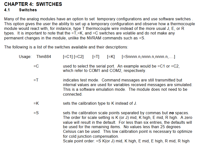
Many simulation modules can be temporarily configured and software switches can be used, such as observing the reaction of thermocouple modules using T-shaped thermocouple wires (rather than the commonly used J, E, R types); Please note that the=T,=K, and=C switches are volatile and will not cause permanent changes to the module, while commands such as=NVRAM (such as=S) will cause permanent changes. The switch format is "Thm884 [=C1] [=C2] [=T] [=K] [=Snnnn. n, nnnn. n, nnnn. n,...]", and the functions of each switch are as follows:
Switch Function Description
=C is used to select serial ports, for example=C1 (COM1),=C2 (COM2)
=T represents test mode, still transmitting command messages, but variables use internal values, receiving messages generated by simulation (software simulation mode), without the need to connect modules
=K sets the calibration type to K instead of the default J type
=Set calibration scale points for S, separated by commas (without spaces), in the order of K (or J) median, K high value, E median, E high value, R median, and R high value; When the value is 0, use the default value; If there are less than 6 entries, the remaining entries will use default values; The scale point must not be lower than 25 degrees Celsius (this low-temperature calibration point is crucial for optimizing cold end compensation)
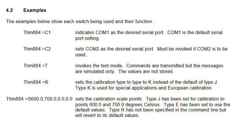
(2) Example (4.2)
Command function
Thm884=C1 specifies COM1 as the serial port (default port)
Thm884=C2 specifies COM2 as the serial port (this command needs to be called to use COM2)
Thm884=T Enable test mode, transmit commands but only simulate messages, do not store values
Thm884=K sets the calibration type to K type (default J type), suitable for special applications and European calibration
Thm884 =S600.0,700
- YOKOGAWA
- Reliance
- ADVANCED
- SEW
- ProSoft
- WATLOW
- Kongsberg
- FANUC
- VSD
- DCS
- PLC
- man-machine
- Covid-19
- Energy and Gender
- Energy Access
- Renewable Integration
- Energy Subsidies
- Energy and Water
- Net zero emission
- Energy Security
- Critical Minerals
- A-B
- petroleum
- Mine scale
- Sewage treatment
- cement
- architecture
- Industrial information
- New energy
- Automobile market
- electricity
- Construction site
- HIMA
- ABB
- Rockwell
- Schneider Modicon
- Siemens
- xYCOM
- Yaskawa
- Woodward
- BOSCH Rexroth
- MOOG
- General Electric
- American NI
- Rolls-Royce
- CTI
- Honeywell
- EMERSON
- MAN
- GE
- TRICONEX
- Control Wave
- ALSTOM
- AMAT
- STUDER
- KONGSBERG
- MOTOROLA
- DANAHER MOTION
- Bentley
- Galil
- EATON
- MOLEX
- Triconex
- DEIF
- B&W
- ZYGO
- Aerotech
- DANFOSS
- KOLLMORGEN
- Beijer
- Endress+Hauser
- schneider
- Foxboro
- KB
- REXROTH
- YAMAHA
- Johnson
- Westinghouse
- WAGO
- TOSHIBA
- TEKTRONIX
- BENDER
- BMCM
- SMC
- HITACHI
- HIRSCHMANN
- XP POWER
- Baldor
- Meggitt
- SHINKAWA
- Other Brands
- UniOP
- KUKA
- IBA
- Beckhoff
- ADLINK
-
Beckhoff EP9224-0037 - 4-Channel Power Distribution Box EtherCAT
-
Beckhoff CX2900-0026 - Solid State Flash Memory Card 20GB CFast
-
Beckhoff BK7500 - SERCOS Interface Fieldbus Bus Coupler Terminal
-
Beckhoff Ep2328-0002 - 4-Channel Input 4-Channel Output EtherCAT Box IP67
-
Beckhoff CX1020-0111 - Controller Kit Combo Interface Modules
-
B&R X20AI2237 - X20 System Analog Input Interface Module
-
Beckhoff CP2221-0010 - Multi-Touch Built-In Panel PC Touchscreen
-
Beckhoff CX1500-M310 - Fieldbus Master Interface Module 24V
-
Beckhoff CX2100-0904 - Power Charging Module Smart UPS Extension
-
Beckhoff CP3918-0000 - Multi-Touch Control Panel 18.5-Inch Monitor
-
Beckhoff CP2915-0000 - 15-Inch Multi-Touch Built-In Control Panel
-
Beckhoff CP7037-1027 - HMI Industrial Control Panel Built-In PC
-
Beckhoff EL3152 - 2-Channel Analog Input Terminal 4-20mA EtherCAT
-
Beckhoff CP6607-0000-0020 - 5.7-Inch Built-In Panel PC HMI Touch
-
Beckhoff EJ1809-0000 - 16-Channel Digital Input Pluggable Signal Level Terminal
-
Beckhoff AM8563-0N10-0000 - Synchronous Servo Motor
-
Beckhoff AX2006-S60600-520 - Compact Servo Drive Inverter
-
Beckhoff AM8053-0K20-0000 - Servo Motor with Planetary Gearbox AG3210
-
Beckhoff AM8042-0FH1-0000 - Synchronous Servo Motor
-
Rexroth R911338600 - IndraControl V HMI Terminal Beckhoff PCI Card FC9002
-
Beckhoff AX5125-0000 - 3 Phase Industrial Servo Drive 1000Hz
-
Beckhoff EP2328-0002 - 4-Channel Digital Input 4-Channel Output EtherCAT Box
-
B&R 7CP476-02 - System 2005 RTD CPU Module 3IF681.86 Interface
-
Beckhoff AX8620-0000-0000 - Power Supply Module Axis Drive System
-
Beckhoff CX1010-0111 - PLC Module CPU Controller 24V
-
Beckhoff AM8043-0H10-0000 - Synchronous Servo Motor
-
Beckhoff C6240-1009 - Control Cabinet Industrial PC Mainframe
-
Beckhoff BX8000-0000 - Bus Terminal Controller HW 4.4 Standalone
-
Beckhoff CP7721-1089-0020 - 12.1-Inch Touch Screen HMI Panel PC
-
Beckhoff CP7132-0001 - Industrial Built-In Panel PC Screen
-
Beckhoff CP2912-0010 - Multi-Touch Built-In Control Panel Display
-
Beckhoff CP2915-0000 - 15-Inch Multi-Touch Built-In Control Panel
-
Beckhoff AM8532-1EN0-0000 - Synchronous Servo Motor
-
Beckhoff AX5203-0000 - 2-Channel Digital Compact Servo Drive
-
Beckhoff CX2020-0141 - Embedded PC Core CPU Module
-
Beckhoff CP6832-0002-0010 - Built-In Industrial Control Panel Display
-
Beckhoff CX5020-0112 - Embedded PC CPU Control Module
-
Beckhoff CX5140-0175 - 4GB Embedded PC CPU Unit 24V
-
Beckhoff EL3681-0030 - Digital Multimeter Calibration Terminal EtherCAT
-
Beckhoff CP7201-1000-0000 - Industrial PC Touch Screen HMI Monitor
-
Beckhoff CP7232-1001-0000 - Industrial Panel PC Touch Screen
-
Beckhoff C6930-1032-0040 - Control Cabinet Industrial PC System
-
Beckhoff AX5125-0000 - 3 Phase Industrial Servo Drive 1000Hz
-
Beckhoff CP3916-1424-0000 - Multi-Touch Built-In Control Panel
-
B&R 1900071142 - Lemoine Fieldbus Communication Interface Module
-
Beckhoff EL2872 - 16-Channel Ribbon Cable Digital Output Terminal
-
Beckhoff CX2030-0120 - Embedded PC CPU Base Module Controller
-
Beckhoff CP3919-0000 - 19-Inch Multi-Touch Control Panel Touchscreen
-
Beckhoff AX5101-0000-0202 - Servo Driver Compact Intelligent Drive 180V
-
Beckhoff CX5130-0135 - Embedded PC Controller Module
-
Beckhoff CP3719-1061-0010 - Multi-Touch Panel PC Outer Housing Enclosure
-
Beckhoff CP3919-1033-0000 - 19-Inch Touch Industrial Panel Keyboard
-
Beckhoff CX5020-0111 - Embedded PC PLC CPU Module
-
Beckhoff FC5102-0000 - 2-Channel CANopen PCI Control Board Card
-
Beckhoff CX9001-1101 - Embedded PC CPU Network I/O System Module
-
Beckhoff CX1100-0920 - Smart Position Sensor Interface Module
-
B&R 4P3040.01-490 - Operator Panel PLC Interface Communication Module
-
Beckhoff CP2612-0000 - Dual-Touch Built-In Panel PC HMI
-
Beckhoff CP7002-1043-0010 - Touchscreen Display HMI Panel Terminal
-
Beckhoff CX9020-0115 - Embedded PC Controller Module
-
Beckhoff CX5140-0155 - 4GB Embedded PC CPU Module Die Industry
-
B&R 7DI435.7 - System 2005 Universal Digital Input Output Module
-
Bihl+Wiedemann BWU1568 - AS-i Master to Profibus Gateway Module
-
Beckhoff C6920-0070 - Control Cabinet Industrial PC 8GB Win 10
-
B&R X20AI2322 - 2-Channel Temperature Analog Input Module
-
Beckhoff CP2912-0000 - 12-Inch Touchscreen Display Monitor Screen
-
Beckhoff CP6022-1001-0010 - 15-Inch Built-In Control Panel
-
Beckhoff AM8031-0D10-0000 - Synchronous Servo Motor
-
Beckhoff CX5010-0111 - Embedded PC Controller CPU Module
-
Beckhoff CP7232-1000-0000 - Industrial Panel PC Touch Display Screen
-
Beckhoff CP7802-0011-0000 - 15-Inch Industrial Touchscreen Control Panel
-
Beckhoff C6320 - Control Cabinet Industrial PC
-
Beckhoff CX1030-0012 - Basic CPU Module Windows CE 6.0
-
Beckhoff CP2919-0000 - Installation Multi-Touch Control Panel
-
Beckhoff CX1020-0000 - Controller Set Stack System Pack
-
B&R 3DO480.6 - System 2005 Digital Output Module
-
Beckhoff EL3101 - 1-Channel Analog Input Terminal Differential +/-10V
-
Beckhoff AX8108-0200-0000 - Axis Feed Module Servo Drive
-
Beckhoff CP7802-1241-0010 - 15-Inch Industrial Touchscreen Control Panel
-
Beckhoff FC2002-0000 - 2-Channel Lightbus Data Acquisition PCI Card
-
Beckhoff CX5120-0155 - 2GB Embedded PC Intel Atom Controller
-
Beckhoff Cx9020-0111 - 1GB Basic CPU Module Embedded PC
-
Beckhoff CP6901-0001-0000 - 12-Inch Economy Built-In Control Panel
-
Beckhoff CX9020-0111 - Embedded PC CPU Basic Module
-
Beckhoff CX5130-0100 - 4GB Embedded PC CPU Module
-
Beckhoff CP2715-0010 - Multi-Touch Built-In Panel PC
-
Beckhoff CX2033-0175 - Embedded PC CPU Module Core i7
-
Beckhoff CP7201-1000-0000 - 12-Inch Touchscreen Panel PC AMAT Green Box
-
Beckhoff EL4038 - 8-Channel Analog Output Terminal 0-10V EtherCAT
-
Beckhoff CP6802-0000-0000 - Built-In Control Panel HMI Screen
-
Beckhoff CP6500-1012-0060 - Control Cabinet PC Interface Unit
-
Beckhoff FC5202-0000 - 2-Channel DeviceNet Master PCI Interface Card
-
Beckhoff CP6606-0001-0020 - 7-Inch Economy Panel PC Touch
-
Beckhoff CP2921-0010 - Multi-Touch Integrated Control Panel Display
-
Beckhoff CP7802-0001-0010 - 15-Inch Touch Screen Control Panel HMI
-
Beckhoff C6920-0050 - Control Cabinet Industrial PC
-
Beckhoff BK9105 - EtherNet/IP Bus Coupler Network Interface
-
Beckhoff 31 Modules - Bus Terminal Slice I/O Lot Assortment
-
Beckhoff CX2020-0120 - Embedded PC Basic CPU Module 8GB CFast Card
-
Beckhoff CP7001-0000 - HMI Control Panel Touch Screen
-
B&R 7EX484.50-1 - System 2005 Controller Base Module Slots
-
Beckhoff EK1322 - 2-Port EtherCAT P Extension Feed-In Terminal
-
Beckhoff CP6606-0001-0020 - 7-Inch Single-Touch Economy Panel PC
-
Beckhoff CP6607-0001-0000 - Economy Installation Operator Panel PC 5.7-Inch
-
Beckhoff AX5103-0000-0200 - Digital Compact Servo Driver 3 Phase
-
Beckhoff CP7802-0001-0010 - 15-Inch Touch Screen Control Panel
-
Beckhoff AX8620 - Power Supply Module Axis System
-
Beckhoff CX2030-0121 - Embedded PC Controller Module
-
Beckhoff CP6606-0001-0020 - 7-Inch Economy Panel PC Touch Screen
-
Beckhoff CX2030-0121 - Embedded PC CPU Module Windows Standard 7
-
Beckhoff BX3100-0000 - PROFIBUS DP Bus Terminal Controller
-
Beckhoff CX1020-0000 - Controller Set with Power Supply Unit
-
Beckhoff EK1100 - EtherCAT Coupler Terminal Module Set
-
Beckhoff CP7002-1043-0010 - HMI Display Panel with Control Panel Bracket
-
Beckhoff AM8031-0D10-0000 - Synchronous Servo Motor
-
Beckhoff CX5130-0175 - Embedded PC 4GB RAM Controller
-
Beckhoff CX5130-0155 - Embedded PC Automation Controller
-
Beckhoff C6930-0010 - Control Cabinet Industrial PC Core Duo
-
Beckhoff CP3924-0000 - Multi-Touch Control Panel Display
-
Beckhoff AM8023-0F20-0000 - Synchronous Servo Motor
-
B&R KL3362 - Bus Terminal Thermocouple Input Module
-
Beckhoff AL2006-0000-0000 - Linear Servo Motor Three Phase
-
Beckhoff CX5140-0155 - Embedded PC CPU Controller Module
-
Beckhoff FC9002 - Ethernet PCI Network Interface Card
-
Beckhoff CP7203-0021-0040 - Built-In Panel PC 19-Inch Touch Screen
-
Beckhoff C6930-0020 - Control Cabinet Industrial PC HDD CF Card
-
Beckhoff CX2900-0033 - Memory Card CFast Storage
-
Beckhoff CP6201-0001-0020 - Built-In Panel PC Display

K-JIANG

Add: Jimei North Road, Jimei District, Xiamen, Fujian, China
Tell:+86-15305925923