
K-WANG


HIMA HIMatrix F35 Manual Safety-Related Controller
HIMA HIMatrix F35 Manual Safety-Related Controller
Product Overview
1. Core positioning and certification
HIMatrix F35 is a high safety compact programmable electronic controller launched by HIMA, designed specifically for industrial automation safety control scenarios. It can replace traditional decentralized relay circuits and is suitable for safety related functions such as emergency shutdown, process protection, and equipment interlocking. This controller has been certified by T Ü V and supports up to SIL 3 safety level (compliant with IEC 61508, IEC 61511, IEC 62061 standards). It also meets safety specifications such as EN 954-1 Cat.4 and EN ISO 13849-1 PL e, and is suitable for Zone 2 hazardous environments (compliant with EC Directive 94/9/EG ATEX directive). Some models can be used in underwater scenarios (compliant with ISO 13628-6 standard).
2. Model variants and environmental adaptation
The controller offers 6 variants, each adapted to different programming tools and usage environments, with the following core differences:
Model Programming Tool Operating Temperature Special Design Applicable Scenarios
F35 01 ELOP II Factory 0~60 ℃ Standard Metal Shell Conventional Industrial Environment
F35 011 (-20 ℃) ELOP II Factory -20~60 ℃ Electronic components coated with protective paint Low temperature industrial environment
F35 012 (Subsea/-20 ℃) ELOP II Factory -20~60 ℃ V2A stainless steel shell, impact and vibration resistant subsea production control system
F35 01 SILworX SILworX 0~60 ℃ Standard Metal Shell Conventional Industrial Environment (OS ≥ 7 version)
F35 011 SILworX (-20 ℃) SILworX -20~60 ℃ Electronic components coated with protective paint Low temperature industrial environment (OS ≥ 7 version)
F35 012 SILworX (Subsea/-20 ℃) SILworX -20~60 ℃ V2A stainless steel shell, impact and vibration resistant subsea production control system (OS ≥ 7 version)
3. Physical and Electrical Basic Parameters
Protection level: IP20 (standard), Zone 2 environment needs to be equipped with a protective shell of IP54 or above;
Power supply requirements: 24VDC (-15%~+20%), in compliance with SELV/PELV safety standards, external 10A delay fuse needs to be connected in series;
Power consumption: 15-29W (varying with output load);
Physical dimensions: width 257mm x height 114mm x depth 97mm (excluding plug);
Weight: The standard model weighs about 1.2kg, while the subsea model weighs about 1.7kg;
Storage temperature: -40~+85 ℃, altitude<2000m, pollution level II (compliant with IEC/EN 61131-2).
Hardware configuration and functional details
1. Core configuration of input/output/counter
(1) Digital input (24 channels)
Electrical characteristics: Non isolated, current absorption logic, 24V type 1 (compliant with IEC 61131-2);
Voltage range: 0~30V, default low level<7V, high level>13V, threshold can be customized through system parameters;
Current parameters: approximately 3.5mA at 24V, approximately 4.5mA at 30V, input resistance<7k Ω;
Overload protection: -10V~+35V overvoltage protection;
Wiring and power supply: divided into 3 groups (8 channels per group), each group is powered by independent LS+(24V), supporting passive mechanical contacts and active signal source connections, with a maximum wiring distance of 300m;
Safety feature: Following the principle of "power-off tripping", a low-level safety state is output in case of a fault, and channel faults are fed back through ERROR CODE.
(2) Digital output (8 channels)
Load capacity: Channels 1-3/5-7( 0.5A@60 ℃), channel 4/8( 1A@60 ℃ 2A@50 ℃), minimum load 2mA/channel;
Electrical characteristics: Non isolated, common ground (L -) design, output voltage of L+minus 2V, maximum internal voltage drop of 2W (at 2A), leakage current ≤ 1mA (at low level);
Overload protection: Automatic power-off in case of single channel overload, and automatic restoration after fault relief; When the total current exceeds 7A, all outputs will be powered off and the cycle will retry;
Wiring requirements: The 1-pole switch output should be paired with the corresponding channel group's L-ground (2-pole connection), and it is recommended to parallel protect diodes for inductive loads;
Safety feature: When a module or channel fails, the output switches to a power-off safety state and activates the FAULT LED indicator light.
(3) Analog input (8 channels)
Measurement range: Unipolar 0~10V voltage (12 bit resolution), 0~20mA current (requires external Z7301/Z7302 shunt adapter);
Accuracy indicators: Measurement accuracy at 25 ℃ ± 0.1% full range, full temperature range ± 0.5% full range, safety related accuracy ± 2% full range;
Electrical characteristics: Input resistance of 1M Ω, internal resistance of signal source ≤ 500 Ω, sampling time of about 45 μ s, measurement value refreshed once per controller cycle;
Power supply and wiring: Each channel is equipped with a 24~28V, ≤ 46mA short-circuit protection transmitter power supply, which requires the use of shielded twisted pair cables (up to 300m in length), with the shielding layer grounded at one end (controller side). Unused channels need to be short circuited;
Extended function: Short circuit/open circuit monitoring of digital output can be achieved through external resistors and voltage regulators (compliant with SIL 3 requirements).
(4) Counter (2 independent channels)
Electrical characteristics: Non isolated, supports 5V/24V input voltage (configured through system parameters), input current 1.4mA (5V)/6.5mA (24V), input impedance 3.7k Ω;
Performance parameters: 24 bit resolution, maximum count value 16777215, minimum pulse width 5 μ s, maximum input frequency 100kHz (5V/24V), trigger edge as falling edge, pulse duty cycle 1:1;
Working mode: Supports 3 modes - ① Direction controllable counting (input B controls increase or decrease); ② Fixed direction counting (user program controls increase or decrease); ③ Gray code decoding (compatible with 3-bit absolute rotary encoder);
Wiring requirements: Each channel contains 3 inputs: A (counting input), B (direction/bit 1), and Z (reset/bit 2), with a maximum wiring distance of 500m, and both ends of the shielded twisted pair are grounded.
2. Communication interface configuration
(1) Ethernet interface (4 RJ-45 ports)
Transmission characteristics: Supports 10/100Base-T, half duplex/full duplex automatic negotiation, Auto Crossover automatic adaptation to cable types;
Protocol support: Safety related protocols (safeEthernet), non safety protocols (Modbus TCP, OPC, SNTP, TCP-SR), EtherNet/IP only supports ELOP II Factory;
Port allocation: UDP ports (8000 for programming tools, 8001/ELOP II Factory remote I/O configuration, 8004/SILworX remote I/O configuration, 502/Modbus), TCP ports (502/Modbus, 44818/EtherNet/IP);
Hardware features: Integrated switch, MAC address fixed (pasted above the port), IP address and subnet mask can be freely configured (default IP: 192.168.0.99).
(2) Fieldbus interface (3 9-pin D-sub connectors)
Interface support module compatible protocol core usage
FB1 PROFIBUS master/slave, RS485/RS232/RS422, INTERBUS master PROFIBUS DP, Modbus, ComUserTask master fieldbus communication
FB2 communicates with FB1 via redundant or backup fieldbus
FB3 fixed RS485 Modbus (master/slave), ComUserTask auxiliary fieldbus communication
3. Other hardware functions
LED indicator lights: including power light (24VDC green), system light (RUN/RROR/ROG/FORCE/AULT, etc.), communication light (Ethernet/fieldbus status), I/O light (independent indication for each channel), all LEDs light up synchronously during boot;
Reset button: located in the upper left corner of the casing, it needs to be long pressed with an insulating pin for 20 seconds and restarted to activate the controller. After resetting, the IP address (default 60000.0.0) and system ID will be restored to default, only valid for administrator accounts;
Hardware clock: Built in gold capacitor, can maintain the clock for about one week after power failure;
ESD protection: It is necessary to wear an anti-static wristband for operation, and store it in its original packaging when idle.
Software Programming and Configuration
1. Adaptation of programming tools
SILworX: Suitable for processor OS version ≥ 7, communication OS ≥ 12, supports hardware parameter configuration, variable mapping, fault code reading, project files are not compatible with ELOP II Factory;
ELOP II Factory: Suitable for processor OS version<7, communication OS<12, supports signal editing, channel assignment, protocol configuration, can be used to upgrade OS to version 7 and above, and later switch to SILworX.
2. Core configuration functions
(1) Variable and parameter configuration
Digital input: configurable channel enabled (Used), Hysteresis LOW/HIGH threshold, read analog values (0~3000 corresponds to 0~30V) and fault codes;
Digital output: Configure output values (BOOL type, 1=energized/0=de energized), read channel and module fault codes;
Analog input: Select resolution (FS1000:0~1000/0~10V; FS2000:0~2000/0~10V), configure channel enable, read measurement values and fault codes;
Counter: Configure input voltage (5V/24V), working mode, counting direction, reset mode, read count value, timestamp, overflow status, and fault code.
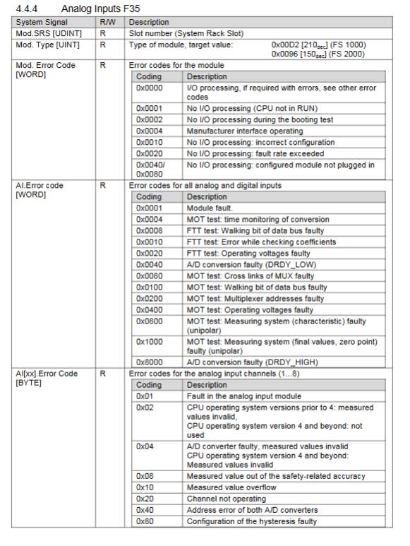
(2) Fault code system
The controller outputs fault codes through system variables, supporting channel level and module level fault localization. The core fault codes have the following meanings:
Digital input faults: 0x01 (module fault), 0x04 (A/D converter fault), 0x08 (measurement value exceeding safety accuracy), etc;
Digital output faults: 0x02 (overload power-off), 0x04 (output value read back error), 0x200 (total current exceeding limit), etc;
Analog input faults: 0x04 (A/D conversion fault), 0x08 (measurement value exceeds safety accuracy), 0x20 (channel not enabled), etc;
Counter malfunction: 0x02 (incorrect comparison of count values), 0x04 (incorrect comparison of timestamps), 0x08 (incorrect parameter settings), etc.
(3) Wiring variant configuration
Analog input connected to mechanical contacts: Z7308 shunt adapter (overvoltage protection) is required, with a supply voltage of 26.7~27.3V, switching threshold: L → H=6V (1200 digits), H → L=3V (600 digits), fault threshold ≤ 0.5V or ≥ 8.4V;
Digital input connected to mechanical contacts: 3 independent supplies (16.7~26.9V), each requiring 1 digital input to monitor the supply voltage. Switching threshold: L → H>12V, H → L<10V, fault threshold<2V or=supply 1.1V.
Installation and Startup
1. Installation requirements
Installation method: Standard 35mm DIN rail installation, submarine type (F35 012 series) mounting plate fixation;
Additional requirements for Zone 2 environment: ① Installed in a protective enclosure above IP54, with the enclosure labeled "Operable only in power-off state"; ② The shell needs to meet the heat dissipation requirements (15-29W); ③ The power supply is 24VDC PELV/SELV type; ④ The wiring complies with DIN EN 60079-15/14 standard;
Wiring specifications: Shielded twisted pair cables are required for digital input/output/counter/analog input, and wiring should be done according to the terminal definition (see Tables 33-36 for details). The shielding layer should be single ended (controller side) or grounded at both ends (counter).
2. Start the process
Hardware installation and wiring: confirm power polarity, shield grounding, and terminal fastening;
Programming tool connection: Connect PADT (PC+programming tool) through Ethernet port, configure IP address (default 192.168.0.99);
Project configuration: Load or create a project, configure I/O channels, counter modes, communication protocols, and fault response logic;
Download and Start: Download the configuration to the controller, set the module mode to Run, perform a cold start, and the controller enters the RUN state (LED indicator light RUN is always on);
Troubleshooting: If the startup fails, locate the problem (such as configuration mismatch, wiring error) through LED status and programming tool diagnostic logs.
Operation and maintenance
1. Running operation
No manual intervention is required during normal operation, and the status is monitored through LED indicator lights and programming tools;
Forcing: Supports global/local forcing, requires authorization activation, can set time limits, and automatically resets after restart;
Diagnostic function: Read diagnostic logs (including fault time, type, and channel) through SILworX/ELOP II Factory, supporting fault filtering and export.
2. Maintenance points
Regular maintenance: The analog input module is calibrated every 10 years, and the fan (if any) is replaced regularly;
Fault handling: When the OS version ≥ 6.42 fails, it will automatically restart. If the fault is repeated within 1 minute, it will enter the STOP_INVALID state (output power loss); OS<6.42 version directly enters the ERROR STOP state;
Operating system upgrade: Load the new version of OS through programming tools, and place the controller in STOP state before upgrading;
Replacement and scrapping: When a module fails, it needs to be replaced as a whole (only repairable by the manufacturer), and scrapping must comply with environmental requirements. A disposal agreement can be signed with HIMA.
Applicable scenarios and core advantages
1. Typical applications
Safety interlock systems for industries such as petrochemicals, electricity, pharmaceuticals, and automobile manufacturing;
Emergency shutdown (ESD), equipment safety door monitoring, safety light curtain linkage, pressure/temperature over limit protection;
Safety control in Zone 2 hazardous environments (such as gas stations and chemical workshops);
Equipment control for underwater production platforms (F35 012 series).
2. Core advantages
High integration: Compact design integrates 24DI+8DO+2 counters+8AI, saving installation space;
High safety: SIL 3 certification, automatically switches to a safe state in case of failure, supports channel level fault diagnosis;
Environmental adaptability: covering a temperature range of 0-60 ℃/(-20~60 ℃), suitable for conventional/low temperature/underwater/hazardous environments;
Flexible expansion: support multiple communication protocols and wiring variants, and adapt to different sensor/actuator types.
- YOKOGAWA
- Reliance
- ADVANCED
- SEW
- ProSoft
- WATLOW
- Kongsberg
- FANUC
- VSD
- DCS
- PLC
- man-machine
- Covid-19
- Energy and Gender
- Energy Access
- Renewable Integration
- Energy Subsidies
- Energy and Water
- Net zero emission
- Energy Security
- Critical Minerals
- A-B
- petroleum
- Mine scale
- Sewage treatment
- cement
- architecture
- Industrial information
- New energy
- Automobile market
- electricity
- Construction site
- HIMA
- ABB
- Rockwell
- Schneider Modicon
- Siemens
- xYCOM
- Yaskawa
- Woodward
- BOSCH Rexroth
- MOOG
- General Electric
- American NI
- Rolls-Royce
- CTI
- Honeywell
- EMERSON
- MAN
- GE
- TRICONEX
- Control Wave
- ALSTOM
- AMAT
- STUDER
- KONGSBERG
- MOTOROLA
- DANAHER MOTION
- Bentley
- Galil
- EATON
- MOLEX
- Triconex
- DEIF
- B&W
- ZYGO
- Aerotech
- DANFOSS
- KOLLMORGEN
- Beijer
- Endress+Hauser
- schneider
- Foxboro
- KB
- REXROTH
- YAMAHA
- Johnson
- Westinghouse
- WAGO
- TOSHIBA
- TEKTRONIX
- BENDER
- BMCM
- SMC
- HITACHI
- HIRSCHMANN
- XP POWER
- Baldor
- Meggitt
- SHINKAWA
- Other Brands
- UniOP
- KUKA
- IBA
- Beckhoff
-
LTI SC52.0040.0012.0000.0 - Servo Drive
-
Lti SC52.0040.0012.0000.0 - Servo Drive
-
Milton Industries LTI Tool By Milton LT1240 - 1/2" Drive Lugnut Remover
-
LTi Drives SO84.200.P030.0000.0-W - Servo Spindle Drive
-
LTI DRIVES LSP08-035-320-30-B0R1PY170 - Servo Motor
-
LTI DRIVES SE84.200.SC00.0001.0-W - Servo Drive
-
Lust CDE34.005.W2.2 - Lti Drives Controller
-
LTi SO84.012.0030.0011.2 - ServoOne Servo Drive
-
LTi Drives SO CM-P.0010.11.00.0 - Servo Drive Controller
-
LTi CDE34.017.W3.0 - Servo Drive
-
LTI Drives CDB32.004, C2.0,SH - Positioning Controller
-
LUST CM-CAN1 - LTi DRIVES Communication Module
-
LTi SO84.012.1030.0000.2 - Servo Drive
-
LTI MOOG CDE54.044 - PITCHMASTER FREQUENCY CONVERTER 181-01019
-
MOOG LTI 181-01019 CDE54.044 - PITCHMASTER FREQUENCY CONVERTER
-
Lust LTi Drives CDE34.010,D2.0 - Servo Drive Controller
-
LTI SO84.032.0003.0101.2 - Servo Drive
-
Seagate 9CC132-302 Harris LTI-CS IRT-34-0021-01 - Hard Drive 160GB
-
LTI SO84.032.0003.0001.2 - Servo Drive
-
LTI SO24.007.0070.0000.1 - SERVO CONTROLLER
-
LTi drive CDA32.003.C3.0.H05-01.PC1 - Servo Drive
-
LTI SO84.016.0030.0000.2 - SERVO CONTROLLER
-
LUST LTI CD A34.008,W1.4, BR - SERVO DRIVE
-
MOOG LTI 181-01019 CDE54.044 - PITCHMASTER FREQUENCY CONVERTER
-
LTI MOOG 181-01019 - PITCH Master Servo Drive CDE54.044
-
LTI SERVO ONE SO84.045.0030.0001.2-W - Drive
-
LUST LTi SO84.032.0040.0000.2 - SERVO ONE DRIVE
-
LTi Drives LSH-074-2-30-3 20/T1,G6.1M - SERVO MOTOR
-
LTI SO84.016.0000.0101.2 - servo drive
-
LTI SA54.0550.0033.0000.0 - Servo Drive
-
LTI SA54.0550.0033.0000.0 - Servo Drive
-
LTI LT 4850 - 3/8" Drive 3-Pc Twist Socket Transmission Drain Plug Removal System
-
LTI Tools LT4400-30 Lock Technology - 3/4" Twist Socket 1/2" Drive Lugnut Remover
-
LTI Tools LT-1400C - 1/2 Drive Wheel Torque Extension Tool
-
LTI Tools LT1250 - 1/2" Drive Dual Sided Socket Lug Nut Remover Tool
-
LTI SO84.032.0003.0101.2 - Servo Drive
-
LTI MOOG 181-01019 - PITCH Master Servo Drive CDE54.044
-
MOOG LTI 181-01019 CDE54.044 - PITCHMASTER FREQUENCY CONVERTER
-
MOOG LTI 181-01019 CDE54.044 - PITCHMASTER FREQUENCY CONVERTER
-
MOOG LTI 181-01019 CDE54.044 - PITCHMASTER FREQUENCY CONVERTER
-
LTI SA54.0550.0033.0000.0 - Servo Drive
-
LTI Tools LT-4800 - 7 Piece Twist Socket 3/8" Drive Oil Drain Plug Removal Set
-
LTI SA54.0550.0033.0000.0 - Servo Drive
-
LTI Drive SO24.007.00300000.0 - Servo Drive
-
LTI TOOLS LTI 1400-I - Drive Wheel Torque Extension
-
LTI Tools LT4400-3 - 3/4" 19mm Twist Socket 1/2" Drive Lugnut
-
LTI TOOLS LTI 1400-BB - Drive Wheel Torque Extension
-
LTI SO84.032.0003.0101.2 - Servo Drive
-
LTI Tools LT-4512 - 3/8" Drive 12mm Twist Socket
-
LTI MOTION Luster SO84.032.0003.0001.2 - Servo Drive
-
LTI Tool By Milton LT1600P - 1" Drive Torx Stick
-
LTI Lust VF1424L,HF,OP2,S56 - Variable Frequency Drive
-
LUST CDA32.004,C1.4,H08,B0 - SERVO DFRIVE CM-CAN1 Module
-
LTI SO84.045.0002.0001.2-W - Drive
-
LTI Lust VF1404M,C9,PT1,BR1 - Inverter Type VF1404M
-
LTI SA54.0550.0033.0000.0 - Servo Drive
-
LTI Tools LT-1400C - 1/2" Drive Wheel Torque Extension
-
Lust LTI DRiVES CDA32.006, C3.0, H09 - Variateur De Fr茅quence Frequency Inverter
-
LTI MOOG CDE54.044 - PITCH master SERVO DRIVE
-
LTI MOOG CDE54.044 - PITCH master SERVO DRIVE
-
LTI SO84.143.0020.0101.2-W - servo drive
-
LTI MOTION SC34.0200.0011.0000.0 - Servo drives
-
LTI SO84.032.0003.0001.2 - Servo Drive
-
LTI DRIVES GmbH MS100 - Assembly Set Mounting Kit
-
LTI SO84.032.0003.0001.2 - Servo Drive
-
LTI SO84.032.0003.0001.2 - Servo Drive
-
LTI MOTION SO84.032.0003.0101.2 - servo drive
-
LTI SO84.032.0003.0101.2 - Servo Drive
-
LTI MOOG CDE54.044 - PITCH master SERVO DRIVE
-
LTI MOTION CDE32.004.C2.4 - Servo drives
-
LTI CDD34.032锛學x.x锛孊R锛孭C1 - Servo Drive
-
Lust LTI DRiVES CDA32.006, C3.0, H09 - Inversor De Frecuencia Frequency Inverter
-
Lust SO84.008.0030.1000.0 - Servo One LTi Drive
-
LTI MOTION SO84.032.0003.0101.2 - Servo drives
-
LUST LTi CDA32.004,C1.4 - SERVO DRIVE
-
LTI MOOG CDE54.044 - PITCH Master SERVO DRIVE
-
LTI KEBA CDB32.004 C2.7, SH - PN: 08673530 Frequency Inverter
-
LTI Tools LT-1400C - 1/2" Drive Wheel Torque Extension
-
LTI LT1400-E - 1/2" Drive Wheel Torque Extension
-
LTI MOOG 181-01019 - PITCH master SERVO DRIVE CDE54.044
-
LTI LSN-097-0510-30-560/T1 - Actuator Motor
-
LTI Tools LT 4800 - 7 Piece 3/8" Drive Twist Socket Oil Drain Plug Removal System
-
LTI DRIVES GmbH MS100 - MONTAGESET Assembly Set Mounting Kit
-
Lti SC52.0040.0012.0000.0 - Servo Drive
-
LTI DRIVES GmbH MS100 - Juego De Montaje Assembly Set Mounting Kit
-
LTi DSM4-14.2-21R83-200 - Drives servomoteur Servo Motor
-
MOOG CDE 54.044.GDA - Pitch Master Industrielle Turbine Lti Drive
-
LTI SO24.004.0030.1000.0 - Servo Drive Controller
-
Lti MOOG CDE54.044 - Pitch Master Servo Drive
-
Lust LTI DRiVES CDA32.006, C3.0, H09 - Inverter
-
LTI MOTION GMBH CDB34.006,W3.0,PC1,H39 - Frequency inverter
-
LTI SO84.032.0003.0001.2 - Servo Drive
-
MOOG CDE 54.044.D - Pitch Master Industrielle Turbine Lti Drive
-
LTI TOOLS LT-1460 - 1/2" DRIVE WHEEL TORQUE EXTENSION KIT 5 PIECE SET
-
Lust Cdb32.003, C2.4 - Lti Drives Servoregulador Frecuencia Servo Controller Inverter
-
Lust LTI DRIVES CDA32.006, C3.0, H09 - Frequency Inverter
-
Lust Lti SO82.004.0030.0000.2 - Servo Drive
-
LTI MOTION SC34.0200.0011.0000.0-SL - Servo drives
-
LTI MOTION SA54.0075.0033.0000.0 - Servo drives
-
LTI MOTION SC32.0075.1011.0000.0 - Servo drives
-
LTI Servo-One Junior SO22.006.0080.1000.0 - Servo Controller Servoregler
-
LUST CDA32.004, C1.4, H08, B0 - Servo Drive & LTI CM-CAN1 Module
-
LTI DRIVES LSP08-035-320-30-B0R1PY170 - Servo Motor
-
LUST LTI CDA32.004,C1.4.H08.B0 - SERVO CONTROLLER DRIVES
-
LUST LTi DRiVES CDS44.072LC1.2 - Servo Drive
-
Lti Servo-One Junior SO22.006.0082.1000.0 - Servo Controller Servoregler
-
LUST CDA32.008,C2.0,HF - Lti DRIVES Spindle Drive Inverter
-
LTI SO22.003.0082.0000.0 - Servo Drives One junior Servo Controller Servoregler
-
Lust Lti Drives CM-CAN1 - Communication Module
-
LUST Lti Drives Vf1202s, G8, I6 - Frequency Inverter Drive
-
LTI DRIVES BR-090.03.540.UR.H38 - Bremswiderstand Brake Resistor
-
LTi DRIVES PM-E40.2DRA054P - Wind Turbine Pitch Control Inverter
-
LTi Drives GmbH br-110.01.540-UR - Brake Resistor
-
LTI Drives LSN-097-0960-30-0560/T1,S4,B - Servo Motor
-
LUST CDA34.006.C2.0 - LTI Drives Servoregler
-
LUST LTI DRIVES SERVO ONE JUNIOR SO24.002.0020.0000.1 - Servo Drive Controller
-
LTI MOTION SO84.032.0003.0001.2 - Servo drives
-
LTI DDTD750V2-120 - IBOP ACTUATOR CYLINDER FOR TOP DRIVE
-
LTI CDE32.004, C2.4 - SERVO DRIVE
-
LUST LTI DRIVES CDD34.017 W3.4PC1 - Servo Drive Controller
-
LTI CDA3208,C3,0,HF - AC SERVO DRIVE
-
LUST LTI DRIVES LSH-074-3-30-560/T1,G6.1S - SERVO MOTOR
-
LUST Lti CDB32.004.C2.4.SH - AC Servo Drive
-
LTi CDA32.006, C3.0, H09 - Servo Drive
-
LTI SO22.003.0010.0000.0 - Servo Drive Servo one junior Servoregler Controller
-
LTi Drives DSM4-14.2-21R83-200 - Servo Motor
-
LUST Lti Drives Lsh-097-1-30-560/T1, 1R - Servomotor
-
LTI 1237 - 7 Piece 1/2" Drive Flip Socket Set

K-JIANG

Add: Jimei North Road, Jimei District, Xiamen, Fujian, China
Tell:+86-15305925923