
K-WANG


HONEYWELL EC7830A, RM7830A, EC7850A, RM7850A 7800 SERIES Relay Modules
HONEYWELL EC7830A/RM7830A (switch type) and EC7850A/RM7850A (fully modulated) 7800 series relay modules
Core positioning and functions of the product
Product classification and application
Switch type (EC7830A/RM7830A): suitable for burner on/off control, supporting gas, fuel or mixed fuel single burner;
Full modulation type (EC7850A/RM7850A): suitable for full range modulation control of burners, covering all characteristics of switch type and adding combustion rate regulation function.
core functionality
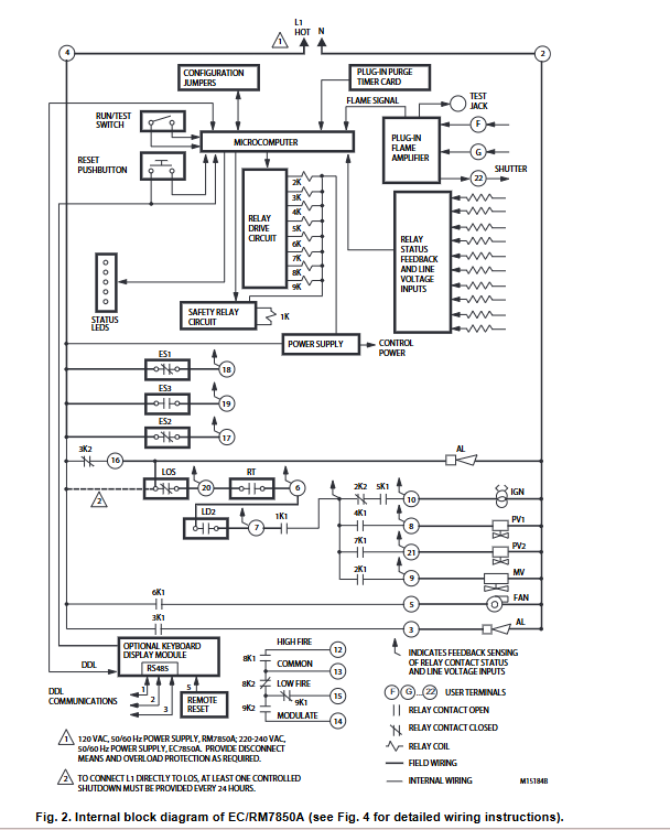
Automatic combustion timing control: covering the entire process of blowing, ignition, pilot stability, main fuel supply, and post blowing;
Safety protection: flame monitoring, airflow switch detection, pre ignition interlock, overvoltage/undervoltage protection, etc. Abnormal working conditions immediately trigger safety lockout;
Status and diagnosis: LED indicator lights (POWER/PILOT/FLAME/MAIN/ALARM) display the running phase, supporting self diagnosis and troubleshooting;
Additional features: optional KDM (multilingual text display, supporting 7 languages including English/Spanish/French), MODBUS communication, remote reset, etc.
Key technical specifications
Specification category specific parameters
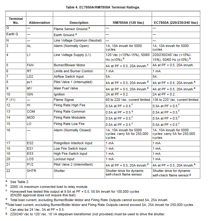
Power supply parameters RM series: 120Vac (+10%/-15%), 50/60Hz (± 10%); EC series: 220-240Vac (+10%/-15%), 50/60Hz (± 10%)
Electrical characteristics: Power consumption ≤ 10W, maximum load 2000VA, rapid melting of fuse 15A (SC type or equivalent)
Environmental conditions: Operating temperature: -40 ° C~60 ° C; Storage temperature: -40 ° C~66 ° C; Humidity: ≤ 85% RH (non condensing); Vibration ≤ 0.5G
Certification standards in Europe: EN298, 90/396/EEC (gas appliances), 73/23/EEC (low voltage); USA: FM certification FCC Class B; Compatible with SIL 3 safety instrumented system
Terminal load fan terminal: 4A (PF=0.5), 20A surge; Main fuel valve/pilot valve: 4A (PF=0.5), 20A surge; Ignition terminal: 2A (PF=0.2)
Installation specifications and requirements
Installation prerequisites
Operator: must be a trained combustion safety technician;
Safety preparation: Disconnect all power sources (there may be multiple disconnection points) and close the manual fuel shut-off valve before installation to avoid the risk of fire/explosion.
Installation location requirements
Humidity: Avoid condensation environment, relative humidity ≤ 85% RH (no condensation);
Vibration: The vibration in the installation area should be ≤ 0.5G, otherwise it will affect the stability of the equipment;
Protection: Outdoor installation requires a rainproof sealed shell, and the equipment itself does not have rainproof function;
Space: Reserve maintenance space, with an additional 51mm reserved below the module for flame amplifier installation and 76mm reserved on both sides for signal probes.
Wiring specifications
Wiring standards: comply with NEC Class 1 (line voltage) wiring requirements and follow local electrical specifications;
Line separation: High voltage ignition lines, flame detectors, and communication lines cannot be wired in the same tube; The low-voltage signal line (KDM/remote reset) needs to be physically separated from the line voltage line;
Wire specifications: 14/16/18AWG copper wire (600V insulated) is used for wire voltage terminals; 22AWG twisted pair shielded wire (Belden 8723 or equivalent) is used for KDM/communication lines;
Grounding requirements: The base and control panel should be reliably grounded (14AWG copper wire), and the signal shielding layer should be grounded at both ends to avoid interference.
Module installation
Base installation: Vertical installation (recommended), prohibit horizontal installation with fork contacts facing downwards; Fix with 4 No. 6 screws (not provided);
Module fixation: Plug in installation, align the L-shaped guide groove with the blade terminal, tighten the 2 fixing screws (to avoid plastic deformation).
Operation timing and safety interlock
Core operation sequence
Initialization: After the power is turned on, it starts for 2 seconds to detect voltage/frequency stability. If there is an abnormality, it triggers a 5-second hold. If it does not recover within 4 minutes, it locks;
STANDBY: After receiving the heat demand signal, wait to enter the purging phase, and all interlock conditions must be met (such as air flow switch closed, pre ignition interlock closed, etc.);
PURGE (blowing): The fan is started, and the EC7850A/RM7850A drives the combustion rate to high speed. The blowing time is 2-30 minutes (can be selected through the blowing card), and the airflow switch is locked if it is not closed within 10 seconds;
Ignition and Stability: After the purge is completed, the ignition transformer is powered on (3 seconds), the pilot valve is opened, and the flame detection passes before entering the pilot stabilization phase (5 seconds);
RUN: The main fuel valve is opened, EC7850A/RM7850A releases the combustion rate modulation function, and continuously monitors the flame and interlock status;
POSTPURGE: After the heat demand is over, the main fuel valve/pilot valve is closed, and the fan continues to run for 2/15/30 seconds (model optional) to discharge residual fuel.
Safety interlock and locking conditions
Key interlocks: Pre ignition interlock (ES2), airflow switch (LD2), lockout input (LOS), high and low ignition switches (EC7850A/RM7850A);
Locking triggering scenarios: detecting flames during the blowing stage, ignition without flames, interlock disconnection, modifying jumper wires after 200 hours, etc. After locking, manual reset is required.
Static verification process
Static verification needs to be completed before module installation to verify that the base wiring and external devices (fans, valves, transformers, etc.) are functioning properly. The core process is as follows (taking EC/RM7850A as an example):
Test number, test content, normal operation, abnormal troubleshooting
The main switch, overload protection, and power wiring of the line voltage are detected between terminal 4-2 of power supply detection
6. The fan and airflow switch detect the start of the fan, and terminal 7 detects the line voltage of the fan circuit, manual fan switch, and airflow switch
7. Ignition detection: Spark (or buzzing sound) generated by ignition transformer, cleanliness of ignition electrode, ignition transformer
8 Pilot valve detection pilot valve open (hear valve action sound) pilot valve actuator, pilot valve wiring
10 Main fuel valve detection Main fuel valve opening Main valve actuator, Main valve wiring
12. High flame switch detects the combustion rate of the motor driven to high speed, and terminal 19 measures the line voltage of the high flame switch, combustion rate motor/transformer
14. Combustion rate modulation detection and adjustment of 90 series controller set value, bidirectional drive of motor 90 series controller, combustion rate motor
Key points of configuration and maintenance
Configurable jumper (modifiable within 200 hours)
Jumper Number Function Description: Intact, Clipped
JR1 first safe time (SAFETY1) 5 seconds (3 seconds for EC7850A1148/RM7850A1035) 3 seconds (2 seconds for EC7850A1148/RM7850A1035)
JR2 Main Trial Time 5 seconds 3 seconds
JR3 airflow switch function without airflow switch (jumper needs to be added between terminals 6-7) with airflow switch (jumper is prohibited)
Maintain taboos
Do not modify the jumper after 200 hours, otherwise it will trigger a non resettable lock (Code 110) and the module needs to be replaced;
Insulation testing is prohibited during module installation as internal surge protectors may be damaged;
After testing, all test jumpers must be removed and bypass limit and interlock devices are prohibited.
- YOKOGAWA
- Reliance
- ADVANCED
- SEW
- ProSoft
- WATLOW
- Kongsberg
- FANUC
- VSD
- DCS
- PLC
- man-machine
- Covid-19
- Energy and Gender
- Energy Access
- Renewable Integration
- Energy Subsidies
- Energy and Water
- Net zero emission
- Energy Security
- Critical Minerals
- A-B
- petroleum
- Mine scale
- Sewage treatment
- cement
- architecture
- Industrial information
- New energy
- Automobile market
- electricity
- Construction site
- HIMA
- ABB
- Rockwell
- Schneider Modicon
- Siemens
- xYCOM
- Yaskawa
- Woodward
- BOSCH Rexroth
- MOOG
- General Electric
- American NI
- Rolls-Royce
- CTI
- Honeywell
- EMERSON
- MAN
- GE
- TRICONEX
- Control Wave
- ALSTOM
- AMAT
- STUDER
- KONGSBERG
- MOTOROLA
- DANAHER MOTION
- Bentley
- Galil
- EATON
- MOLEX
- Triconex
- DEIF
- B&W
- ZYGO
- Aerotech
- DANFOSS
- KOLLMORGEN
- Beijer
- Endress+Hauser
- schneider
- Foxboro
- KB
- REXROTH
- YAMAHA
- Johnson
- Westinghouse
- WAGO
- TOSHIBA
- TEKTRONIX
- BENDER
- BMCM
- SMC
- HITACHI
- HIRSCHMANN
- XP POWER
- Baldor
- Meggitt
- SHINKAWA
- Other Brands
- UniOP
- KUKA
- IBA
- Beckhoff
-
ADLINK CPCI-6860A - 51-31310-OB10 industrial motherboard CompactPCI SBC
-
ADLINK AmITX-SL-G-H110 - 51-7A104-0A30 Mini-ITX Industrial Motherboard
-
ADLINK PXI-2005-003 - CPCI Industrial PC Data Acquisition Card Multi-Function DAQ
-
ADLINK DININ-814M - 51-14032-0A3D SCSI-100P cable connection Interface Terminal Board
-
ADLINK CPCI-3920NA/C2D15/M1G - 3U CompactPCI Intel Core 2 Duo Single Board Computer
-
ADLINK PCIE-8560 - 51-18014-0A20 Communication Card High Speed DAQ
-
ADLINK PCI-C154+ - Motion Control Card 4-axis Motion Controller Board
-
ADLINK PCI-RTV24 - image capture card Analog Video Frame Grabber
-
ADLINK NuPRO-842LV/P - 51-41360-0B30 Industrial Motherboard CPU Board
-
ADLINK cBP-3208/3208R - CPCI Board 3U 8-Slot CompactPCI Backplane
-
ADLINK PCI-8164 - 4-Axis Motion Controller PCI Card 51-12406-0A40
-
ADLINK PCIe-GIE64+ - 4-CH GigE Vision PoE+ Frame Grabber Video Capture Card
-
ADLINK CPCI-6860 / 6860A - CompactPCI Dual Xeon Single Board Computer
-
ADLINK IEC-915GV - REV 1.1 Industrial motherboard CPU Board
-
ADLINK ND-6520 - Technology RS-232 to RS-422RS-485 Converter NuDAM Module
-
ADLINK RTV-24 / PCI-MP4S - 51-12519-1C30 4-Channel Real Time Video Capture Board
-
ADLINK cPCI-6910 / cPCI-6910AM/M1G - cPCI-6910AM/DXL16/M1G/S80G(G)-3120 BOARD CompactPCI SBC
-
ADLINK NUPRO-A40H - Linghua 51-41807-1A30 Industrial Control Computer Motherboard
-
ADLINK USB-3488A - USB to GPIB INTERFACE USB-3488A(G) Controller Module
-
ADLINK PCI-8134A - motion control card 4-Axis Controller Card
-
ADLINK PCI-7432 - Board 32-Channel input / 32-output Isolated Digital I/O PCI Card
-
ADLINK PCI-8134A - 51-12421-0A10 motion controller card tested
-
ADLINK LPCIe-7230 - 32 CH Isolated Input/output Card 2 Interrupts Low Profile PCIe
-
ADLINK NuPRO-E340 - industrial computer motherboard 51-47807-0A30 PICMG 1.3 SHB
-
ADLINK PCI-7434 - High-speed Digital Acquisition Card 64-CH Isolated DO Card
-
ADLINK NuPRO-E330 - 51-41805-0A20 Indsutrial Board SHB Single Board Computer
-
ADLINK PCI-7248 - OPTO-22 48 CHANNEL DIO DIGITAL TTL/DTL I/O 51-12006-0A40 GP
-
ADLINK PCI-8134 - Motion control card 4-Axis Controller Card
-
ADLINK AMP-208C - Movimiento Control Tarjeta 51-12420-1A20 W/Expansión & Breakout
-
ADLINK PCI-8164 - 51-12406-0A40 PCB Board 4-Axis Motion Controller Card
-
ADLINK DIN-68Y-SGII / DIN-68M-J3A - Terminal Board Connector Interface Block
-
ADLINK PCIe-7432 - Technology 51-18402-0A10 PCIe Card With High Input Range
-
ADLINK PCI-8144 / PCI-8144N - Motion control card 4-Axis Stepper Controller Card
-
ADLINK HSL-HUB3/REPEATER - HIGH SPEED LINK EXTENSION MODULES Distributed Hub Module
-
ADLINK ND-6017 - Data Logging + Acquisition 8CH A/D input Mod NuDAM Module
-
ADLINK LPCIe-7250 - data acquisition card Low Profile 8-CH Relay Output Card
-
ADLINK PCI-7432 - I/O card 64-CH Isolated Digital Input Output PCI Card
-
ADLINK IMB-M43H - industrial control computer motherboard Q87 Chip Micro-ATX
-
ADLINK MP-C154 - Motion control Card 4-Axis Motion Controller Board
-
ADLINK PCI-RTV24 - image capture card Video Frame Grabber Card
-
ADLINK PCI-7250 - 8-CH Relay Output & 8-CH Isolated DI Card
-
ADLINK PCI-6308V - 8-CH 12-Bit Isolated Analog Output PCI Card PCB-I-E-1148=6EX2
-
ADLINK PCI-7248 - capture card 48-CH Opto-22 Compatible DIO Card
-
ADLINK HSL-AI16A02-M-VV - Analog Input Output Distributed Module
-
ADLINK NuPRO-A301 - Rev:1.4 NUPRO-A301 PICMG Full-Size Single Board Computer
-
ADLINK PCI-6208V-GL - 8-CH Voltage Analog Output PCI Card
-
ADLINK PCI-8134A - 51-12421-0A10 4-Axis Motion Controller Card
-
ADLINK MNET-S23 - TECHNOLOGY MNET S23 - SERVO DRIVER CONTROL MODULE
-
ADLINK M-342 - ATX I3 I5 I7 Q67 Industrial Motherboard
-
ADLINK NUPRO-780 - Industrial Motherboard CPU Board PICMG SBC
-
ADLINK MP-C154 / MP-C152 - 4-Axis Motion Control Card Pulse-Train Controller
-
ADLINK NuPRO-935A/LV10B0 - Motherboard 51-41802-0A10 GP w/RAM Industrial Control Board
-
ADLINK MP-C154 - Motion control card 4-Axis Motion Controller Mainboard
-
ADLINK PCI-7250 - PCI Acquisition Card 8-CH Relay Output Isolated DI Card
-
ADLINK ACL-7124 - Technology Inc.24 DIO Card Digital Input Output Card
-
ADLINK PCI-8554 A2 - Timer/Counter Data Acquisition Card
-
ADLINK DIN-825-GP4 - Terminal Block Interface Board Breakout Module
-
ADLINK NuPR0-761 - REV:1.1 Industrial motherboard Full-Size PICMG SBC
-
ADLINK MXE-1401/M8G (G) - Matrix Fanless Embedded Computer Industrial PC
-
ADLINK HSL-DI16DO16-UD-NN - Digital 16 Channel I/O Mod Distributed I/O Module
-
ADLINK ND6520 - NUDAM INTELLIGENT DA&C MODULE RS232-RS-422/RS485 CONVERTOR
-
ADLINK NUPRO-761 - REV:1.1 Industrial Motherboard CPU Board
-
ADLINK AMP-208C - Motion Control Card 51-12420-1A20 DSP-based 8-axis
-
ADLINK NuPRO-A301REV 1.4 - with packaging industrial computer motherboard PICMG SBC
-
ADLINK PCM-9112+ - 51-12300-0A2 industrial motherboard Multi-Function DAQ PC/104 Module
-
ADLINK PCM-7250+ - 8-CH Relay Outputs & 8-CH Isolated DI Module PC/104
-
ADLINK PCI-RTV24 - Image capture card Analog Video Frame Grabber
-
ADLINK PCI-8134 - Motion Controller PCI Card 4-Axis Controller Board
-
ADLINK PCI-7432 - Isolated Digital I/O PCI Card
-
ADLINK PCI-8554 A2 - acquisition card Timer/Counter Card
-
ADLINK PCI-8132 - Rev.A2 2-Axis Servo & Stepper Motion Controller Card
-
ADLINK PCI-8132 - Data Acquisition card 2-Axis Motion Controller Card
-
ADLINK EBP-13E4 - 51-46703-0A30 Industrial Backplane Board Passive Backplane
-
ADLINK PCI-800L - Electronic Card Interface Controller Card
-
ADLINK PCIe-GIE72 - 51-18531-0A10 PCB Board GigE Vision Frame Grabber
-
ADLINK DAQ-2010(G)-OOBO - Simultaneous-Sampling Multi-Function DAQ Card
-
ADLINK PCI-9112 - REV.B1 Multifunction DAQ Card Data Acquisition Card
-
ADLINK PCI-7230 - 51-12003-DA60 32-CH Isolated Digital I/O Card
-
ADLINK PCI-7432 - Data Acquisition Card Isolated Digital I/O PCI Card
-
ADLINK ETX-AT-N270-18/LXE - 51-71111-0A20 ETX CPU Module Motherboard
-
ADLINK HSL-DI32-UD-N - DIGITAL INPUT 32 POINTS MODULE Distributed I/O
-
ADLINK AMP-204C - Motion Control card DSP-Based 4-Axis Advanced Controller
-
ADLINK MNET-4XMOG-0050 - Four-axis Motion Controller Distributed Motion Module
-
ADLINK AMP-204C - Motion control card DSP-Based 4-Axis Pulse-Train Controller
-
ADLINK PCI-7442 - Switch card 64-Channel Datalogging & Acquisition Card
-
ADLINK M-302 - Industrial control motherboard ATX PC Board
-
ADLINK NUPRO-852 / NUPRO-852LV - Industrial motherboard Single Board Computer
-
ADLINK PCI-8134 - REV.B1. 4-Axis Motion Controller Card
-
ADLINK PCI-GIE62 + - 51-18502-0A20 2-CH GigE Vision Frame Grabber PoE Card
-
ADLINK PCI-MPG24 - 51-12523-0B20 MPEG4 Card Video Compression Hardware
-
ADLINK HSL-TB32-M-DIN - 32-CH I/O TERMINAL W/ HSL-AI16AO2-M-VV MODULE
-
ADLINK PCI-M114-GL - PCB Ver 2.1 Motion Controller Axis Card
-
ADLINK IMB-M40H - SYM76996H61 motherboard Industrial Computer Mainboard
-
ADLINK NUPRO-A40H - 51-41807-1A20 industrial control motherboard H61 Chip
-
ADLINK PCI-M114-GL - Axis Card Data Acquisition Card PCB VER2.2 Motion Controller
-
ADLINK PCI-8134 - Motion Controller PCI Card 4-Axis Controller Board
-
ADLINK PCI-8102 - Motion control card 2-Axis Servo & Stepper Controller
-
ADLINK NuPRO-841REV:3.0 - motherboard Industrial Control PC Board
-
ADLINK HSL-TB32-U-DIN REV A1 - Breakout Terminal Board Field I/O Module
-
ADLINK AMP-204C - Motion Control card DSP-Based 4-Axis Pulse-Train Controller
-
ADLINK NUPRO-A40H - 51-41807-1A20 industrial control motherboard H61 PC Board
-
ADLINK PCI-6308A / PCI-6308V - 51-12202-0A50 Isolated Analog Output Card
-
ADLINK AMP-204C - DSP-Based 4-Axis Advanced Pulse-Train Motion Controller
-
ADLINK PCI-7434 - Technology 64-Channel Isolated Digital I/O PCI Cards
-
ADLINK CPCI-6840 / CPCI-6840V / PM16/M1G-12G0 - CompactPCI Single Board Computer CPU Module
-
ADLINK PCIE-GIE74 - Motherboard Video Capture Card 51-18531-0A10 Frame Grabber
-
ADLINK NuPRO-E330 - industrial computer equipment motherboard Control Mainboard
-
ADLINK AMP-208C / 51-12420-1A20 - Motion Control Card W/ Expansion & Breakout Board
-
ADLINK HPCI-14S12U - industrial computer baseboard Passive Backplane 14 Slots
-
ADLINK PCI-8164 - 4-Axis Motion Controller PCI Card W/ 1x Cable, 1x Breakout Box
-
ADLINK PCIe-RTV24 - 51-18016-0A20 Image Acquisition Video Capture Card
-
ADLINK M-342 - 5 PCI ATX Motherboard Industrial PC Mainboard
-
ADLINK PCI-FIW64 - 4/2 Channel IEEE1394B Image Capture Card FireWire Frame Grabber
-
ADLINK PCI-7432 - digital IO card 64-CH Isolated Digital Input Output Card
-
ADLINK 51-12001-0C20 - Circuit Board PCI-7200 Data Acquisition Controller Card
-
ADLINK PXI-3920 - PXI 3U cPCI Industrial Controller Embedded System CPU Board
-
ADLINK NuPRO-841REV:2.0 - motherboard Industrial Control PC Board
-
ADLINK NuPro-E330 - 51-41805-0A20 PCB Industrial Control Computer Motherboard
-
ADLINK PCI-RTV24 - Image capture card Analog Video Frame Grabber
-
ADLINK PCI-7442 - Switch card 64-Channel Datalogging & Acquisition Card
-
ADLINK HPX-13S4 - device baseboard Passive Backplane Riser Card
-
ADLINK PCI-9112 REV A.1 - Multi Function DA&C Board Data Acquisition Card
-
ADLINK PCI-7248 - 51-12006-0A40 Card Control 48-CH Digital I/O Module
-
ADLINK CPCI-6860 / 6860A - motherboard CompactPCI Dual Xeon Single Board Computer
-
ADLINK DPAC-3020-11(G) - Embedded PC Automation Controller Machine Control Board
-
ADLINK NuPRO-841 REV:1.0 - industrial control motherboard CPU Board
-
ADLINK MNET-4XMOG-0050 - Four-axis Motion Controller MNET Motion Control Card
-
ADLINK ETX-AT-N270-18/LXE - 51-71111-0A20 ETX CPU Module Motherboard

K-JIANG

Add: Jimei North Road, Jimei District, Xiamen, Fujian, China
Tell:+86-15305925923