
K-WANG


ProSoft Technology ILX56-PBM PROFIBUS DPV1 Master/Slave Module
ProSoft Technology ILX56-PBM PROFIBUS DPV1 Master/Slave Module
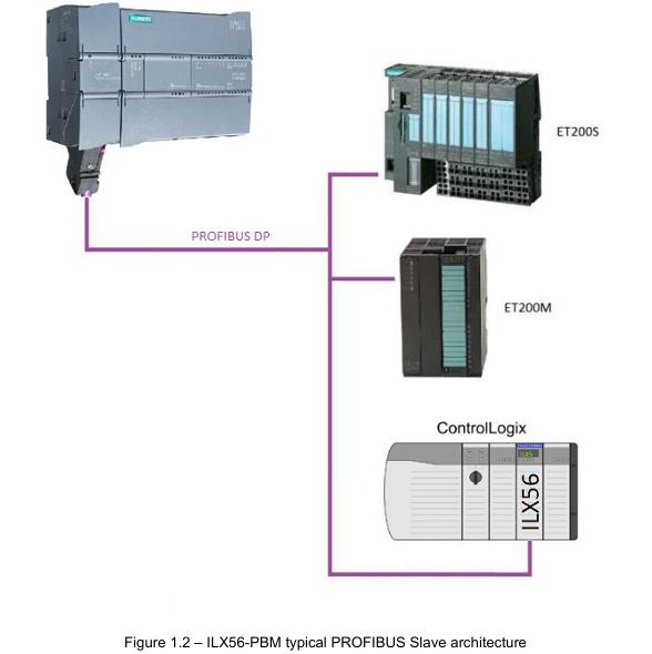
ILX56-PBM is an adaptation of ControlLogix launched by ProSoft Technology ® The PROFIBUS DPV1 master/slave module of the platform enables efficient data exchange between the ControlLogix controller and PROFIBUS DP devices, supports DPV0 cyclic data exchange, DPV1 non cyclic message and alarm functions, and has redundant deployment, flexible configuration, and comprehensive diagnostic capabilities. It is suitable for applications that require the integration of PROFIBUS bus and ControlLogix system in industrial automation, process control, and other scenarios.
Core functions and architecture
1. Work mode and core competencies
ILX56-PBM supports bidirectional switching between master and slave modes, with core functionality covering the full protocol stack of PROFIBUS DPV0/DPV1
Master mode:
Manage up to 125 PROFIBUS DP slave devices, supporting DPV0 cyclic data exchange (up to 5000 bytes of data), DPV1 Class 1 (MS1, only communicates with configured slave devices), and Class 2 (MS2, concurrent communication with multiple master stations) non cyclic messages.
Support DPV1 alarm collection (such as diagnostic alarms and process alarms), which can read device alarm and diagnostic information through the ControlLogix controller, and support automatic device discovery and station address modification.
From mode (Slave):
It can simulate up to 10 PROFIBUS DP slave devices, support DPV0 cyclic data exchange and DPV1 Class 1 messages, and each analog slave device can be configured with independent I/O mapping and alarm triggering mechanisms.
Supports communication with third-party PROFIBUS master stations, automatically adapts data formats to ControlLogix user-defined data types (UDT), and ensures alignment of 16/32-bit data structures.
2. Hardware architecture and interfaces
Physical interface:
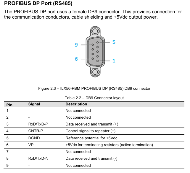
PROFIBUS DP port: RS485 standard DB9 female head, supports+5VDC terminal resistor power supply, pins 3 (RxD/TxD-P) and 8 (RxD/TxD-N) are differential data pins, and pin 5 is reference ground.
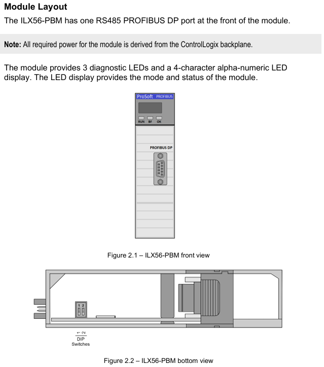
Expansion interface: onboard SD card slot (supporting FAT32 format for firmware backup and configuration recovery), 2 DIP switches (SW1: forced safe mode for firmware repair); SW2: Configuration lock to prevent accidental modifications.
Indicator lights and display: 3 diagnostic LEDs (RUN/FB/OK)+4-character alphanumeric display screen, real-time display module mode (such as "MASTER" and "SLAVE"), operating status (such as "OPERATE" and "OFFLINE"), and fault information (such as "Bus Fault" and "Duplicate Station").
Configuration and deployment process
1. Configuration tools and preliminary preparations
Core tool: ProSoft PLX50 Configuration Utility (available for download from the official website) needs to be installed for module parameter configuration, GSD file management, device addition, and configuration download; Studio 5000 requires the installation of Add On Profile (AOP, v21 and above versions, v20 and below require the use of the universal 1756 module configuration file).
GSD file management: PROFIBUS devices need to be imported into PLX50 tool through GSD files, supporting GSD directory export/import, and can batch add third-party PROFIBUS devices (such as Siemens ET200M, Schneider ATV frequency converter, etc.).
2. Key configuration steps
(1) Basic parameter configuration
Main mode configuration:
Set the PROFIBUS station address (TS, 0-126, which should not conflict with the slave devices), the highest station address (HSA, it is recommended to set it as the actual maximum slave address to optimize performance), and the baud rate (9.6Kbps-12Mbps, which should match all slave devices).
Configure DPV1 parameters: Enable Class 1/Class 2 messages, enable alarms (such as Pull Plug alarms, process alarms), and set timeout time (such as DPV1 request timeout of 2000ms).
From mode configuration:
Simulate the number of slave devices and station addresses, and each slave device needs to be configured with DPV0 data length, DPV1 object (Slot/Index mapping), and alarm triggering conditions (such as Alarm Trigger tag level switching triggering alarms).
(2) ControlLogix Mapping
Generate Logix L5X files using the PLX50 tool, including UDT (such as master status UDT, slave device data UDT), mapping programs, and controller labels. After importing into Studio 5000, automatically associate module input/output mapping areas.
Mapping rule: Input data (from PROFIBUS devices to ControlLogix) and output data (from ControlLogix to PROFIBUS devices) are packaged into byte arrays and automatically parsed into structured labels (such as MyILX56PBM.ET200M.Input. Data) through generated subroutines.
(3) Redundant deployment (exclusive to main mode)
Redundant architecture: Two ILX56-PBM modules share the same PROFIBUS bus, with identical configurations and support for "one master, one backup" switching. The backup machine automatically takes over the main station role by monitoring bus activity (PROFIBUS Inactive Time parameter, default 22ms).
Key parameters:
Profibus Inactive Time: The inactive time of the bus that determines the failure of the main station by the backup machine should be set as "10ms+2 x maximum packet transmission time".
Switch Timeout: The timeout for confirming the primary/backup switch should be set to "Max (1000ms, 4x module RPI)" to avoid switch interruption.
Data interaction and operation
1. Data exchange type
(1) DPV0 cyclic data exchange
Main mode: Interact data with slave devices according to a preset cycle (configurable, minimum 4ms). The input/output data length of each slave device is automatically identified through GSD files, supporting byte/word order exchange (such as AA BB CC DD → BB AA DD CC). In case of communication failure, data can be configured to be forcibly cleared to zero.
From mode: Simulate receiving loop data requests from the PROFIBUS master station, forward ControlLogix output label data to the master station, and write the data issued by the master station to the ControlLogix input label, supporting "Data Exchange Active" status feedback (DataExchange Active label).
(2) DPV1 non cyclic message
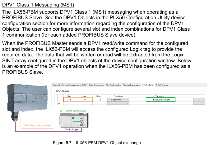
Class 1 (MS1): Interacts only with slave devices that have established loop communication in master mode, used for parameter reading and writing (such as modifying slave device range, reading diagnostic registers). The slave address, Slot number, Index number, and data length need to be specified, and the timeout time can be configured (default 4000ms).
Class 2 (MS2): Supports concurrent communication with multiple master stations, requires establishing a connection through "Initialize", obtaining the connection reference number, and performing read and write operations. After the communication ends, a "Abort" message is sent to release resources, suitable for device debugging and parameter configuration.
(3) Alarm and Diagnosis
Alarm collection: Automatically monitor DPV1 alarms from the slave device in main mode, indicating the alarm status through the DeviceAlarmPending tag. Alarm data (such as alarm type, Slot number, detailed description) can be extracted through CIP messages (service code 0x51).
Diagnostic information: Supports standard diagnostics (such as device unresponsive, data length mismatch) and extended diagnostics (device specific diagnostics based on GSD file parsing, such as module failures, wiring errors), which can be viewed or exported in real-time through the PLX50 tool.
Diagnosis and maintenance
1. Status monitoring and LED indication
Meaning of LED light status (main mode) Meaning of status (slave mode)
RUN often red: PROFIBUS STOP mode; Flash green: CLEAR mode; Evergreen: Operational mode; Off: OFFLINE mode is always off (no RUN status indication from mode)
FB flashing red: from device error; Always red: Bus fault (such as cable disconnection); Extinguish: Normal flashing red: Simulate device error; Constant red: Bus communication failure; Extinguish: Normal
OK often red: Hardware malfunction/firmware damage; Flashing green: No configuration; Evergreen: configured normally and running in the same main mode
Display screen: display mode ("MASTER"/"SLAVE"), operating status ("OPERATE"/"STOP"), fault code (such as "Duplicate" indicating station address conflict).
2. Tool based diagnostic function
PROFIBUS packet capture: The PLX50 tool supports real-time capture of bus packets, displaying frame types (SD2/SD4), source/destination addresses, data length, and raw data. It can filter specific station addresses or frame types (such as Token frames, SRD data frames) to troubleshoot communication anomalies.
Event log: The module has built-in non-volatile memory to store event logs (such as power on, configuration download, and failover), which can be exported as text files using the PLX50 tool, including timestamps, event types, and detailed descriptions.
Online status monitoring: The PLX50 tool provides a "Live List" to display the real-time online status of all devices on the bus (online/offline, data exchange in progress/not yet exchanged), and the "Discovered Nodes" tab can view device manufacturer, model, and GSD file information.
Technical specifications and compatibility
1. Hardware and environmental specifications
Category parameters
Power supply from ControlLogix backplane: 5VDC 450mA, 24Vdc 2mA
Working temperature -20 ° C~+70 ° C (operation), -40 ° C~+85 ° C (storage)
Electromagnetic compatibility (EMC) emission: IEC 61000-6-4; Immunity: EN 61000-4-2 (ESD), EN 61000-4-3 (radiated immunity)
PROFIBUS supports baud rates of 9.6Kbps~12Mbps, maximum bus lengths of 1200m (9.6Kbps) and 100m (12Mbps), and supports repeater expansion
Certified CE, UL (94V-0 flame retardant), ATEX (II 3G Ex ec IIC T4 Gc), IECEx (same as ATEX)
2. Software compatibility
ControlLogix platform: Supports ControlLogix 1756 series controllers, Studio 5000 v21 and above (AOP required), v20 and below require the use of a universal module configuration file.
Operating system: PLX50 Configuration Utility supports Windows 10/11 (64 bit), firmware upgrade requires the use of SD card or PLX50 tool's DeviceFlash function.
Third party devices: compatible with slave devices that comply with the PROFIBUS DP V0/V1 standard (such as Siemens ET200 series, Schneider Lexium drivers), requiring the import of corresponding GSD files.
Configuration and Deployment Tools
1. PLX50 Configuration Utility
Core functions: Project management (create/copy/export), GSD file management (add/delete/import directory), module parameter configuration (master/slave mode, PROFIBUS parameters, Logix connection), configuration download/upload, device discovery and diagnosis.
Key operations:
Generate Logix L5X file: Automatically map PROFIBUS data to ControlLogix tags, including UDT and subroutines.
SD card configuration backup: Save the current configuration to the SD card for quick recovery during module replacement.
2. Studio 5000 Integration
AOP installation: After importing the Add On Profile of ILX56-PBM, modules can be directly added in the I/O configuration to automatically generate Module Defined Data Types.
Tag mapping: By importing the L5X file generated by PLX50, controller tags (such as Local: 1: MasterStatus master status tag, MyILX56PBM-ET200M.Input slave device data tag) are automatically created, supporting online monitoring and forced operations.
Ordering and Support
Typical models and accessories
Core module: ILX56-PBM (basic model, including master/slave mode function).
Supporting accessories:
SD card: used for firmware and configuration backup, requiring FAT32 format (recommended 4GB or above).
Terminal resistor: The end of the PROFIBUS bus needs to be connected to a 220 Ω terminal resistor (pins 3-8 of module DB9 can be powered by+5V).
Transfer cable: PROFIBUS bus extension cable (must comply with PROFIBUS standard, impedance 135-165 Ω, electrical)
- YOKOGAWA
- Reliance
- ADVANCED
- SEW
- ProSoft
- WATLOW
- Kongsberg
- FANUC
- VSD
- DCS
- PLC
- man-machine
- Covid-19
- Energy and Gender
- Energy Access
- Renewable Integration
- Energy Subsidies
- Energy and Water
- Net zero emission
- Energy Security
- Critical Minerals
- A-B
- petroleum
- Mine scale
- Sewage treatment
- cement
- architecture
- Industrial information
- New energy
- Automobile market
- electricity
- Construction site
- HIMA
- ABB
- Rockwell
- Schneider Modicon
- Siemens
- xYCOM
- Yaskawa
- Woodward
- BOSCH Rexroth
- MOOG
- General Electric
- American NI
- Rolls-Royce
- CTI
- Honeywell
- EMERSON
- MAN
- GE
- TRICONEX
- Control Wave
- ALSTOM
- AMAT
- STUDER
- KONGSBERG
- MOTOROLA
- DANAHER MOTION
- Bentley
- Galil
- EATON
- MOLEX
- Triconex
- DEIF
- B&W
- ZYGO
- Aerotech
- DANFOSS
- KOLLMORGEN
- Beijer
- Endress+Hauser
- schneider
- Foxboro
- KB
- REXROTH
- YAMAHA
- Johnson
- Westinghouse
- WAGO
- TOSHIBA
- TEKTRONIX
- BENDER
- BMCM
- SMC
- HITACHI
- HIRSCHMANN
- XP POWER
- Baldor
- Meggitt
- SHINKAWA
- Other Brands
- UniOP
- KUKA
- IBA
- Beckhoff
-
Woodward 8272-796 - Real Power Sensor Module 115/230v-ac
-
Woodward 5463-873 - NetCon Output Module
-
Woodward 8271-567 - Load Sensor Module 120/208v-ac
-
Woodward Type UG-8 P/N 8522-300 EG - Governor R.P.M 1075-1650 With Motor Groschopp
-
WOODWARD 9905-971 REV J - LINKNET 16 CHANNEL DISCRETE INPUT MODULE
-
WOODWARD 8280-3014 - 723 PLUS DIGITAL CONTROL REV NEW
-
Woodward 505DE - Digital Control System
-
Woodward 5453-750 - Ethernet Interface FTM
-
Woodward 9907-018 Rev H - 2301A Load Sharing & Speed Control
-
WOODWARD 5420-1080 V4.3 - BOARD-PPA WITHBOX
-
Woodward b 8271-347SP - 2301 speed control
-
Woodward 9905-795 Rev B - Digital Synchronizer and Load Control
-
Woodward 9905-377 Rev. A - 2301A Load Sharing and Speed Control
-
WOODWARD 8272-582 - Generator speed control module
-
WOODWARD 9907-247 REV K - 828 DIGITAL CONTROL UNIT
-
WOODWARD 5466-353 REV C - NETCON MAIN CHASSIS TRANSCEIVER
-
Woodward Type UG-8 P/N 8524-708 - Governor 760-1560 Governor R.P.M
-
WOODWARD 9907-247 REV K - 828 DIGITAL CONTROL UNIT
-
WOODWARD 8440-1831 REV. H - EASYGEN3000 3200-5 - WITHOUT ACCESSORIES
-
WOODWARD 8444-1002 REV G - UMT1 MEASURING TRANSDUCERS
-
Woodward 5410-312C - Digital Marine Control Printed Circuit Board
-
Woodward 9905-799 REV F - Digital Synchronizer & Load Control , V#456
-
Woodward 9907-014 - 2301A for controller
-
Woodward Type UG-8 P/N B522-446 - Governor R.P.M 500-1200
-
WOODWARD 8272-221 REV.B - DIGITAL REFERENCE UNIT
-
Woodward 8901-037 - Booster Servomotor Single
-
WOODWARD 8444-1019 REV G - UMT 1 MEASURING TRANSDUCER
-
WOODWARD 1767-367 Z21 WK 0920702 - GOVERNOR MOTOR 2700 RPM KM 58-20 K 230V
-
WOODWARD 9905-972 Rev:G - LINKNET 6 CHANNEL 4-20mA OutPut
-
Woodward E8250-501 - Actuator Governor
-
WOODWARD 5466-258 REV M - SIMPLEX DISCRETE I/O MODULE
-
WOODWARD 5501-470 REV E - NETCON CPU MODULE
-
Woodward 8406-120 rev H - egcp-2 digital control
-
Woodward 8440-1799 - Easygen-350 Rev B
-
Woodward 8440-1878 - DSLC-2 Digital Synchronizer Load Control
-
Woodward 5464-843 - Cpu Processor Module
-
WOODWARD 8440-1409 Rev. J - MFR2 MDE Synchronization & Protection MSP
-
Woodward 9907-014 - controller
-
WOODWARD 9907-173 - LOAD SHARING MODULE 120V
-
WOODWARD 8440-1831 REV. K - EASYGEN 3200-5 - WITHOUT ACCESSORIES
-
Woodward 9905-969 - LinkNet Module LinkNet 6C 4-20ma in w/24v
-
Woodward 8520-498 - Governor Type UG-8 Governor R.P.M 850-1650
-
WOODWARD 5466-257 REV.-C - NETCON 5000 MODEL REMOTE TRANSCEIVER I/O MODULE
-
WOODWARD 8800 - 1001 REV-C - DSS-2, 2 CHANNEL DIGITAL SPEED SWITCH
-
WOODWARD 5501-467 REV. C - MICRONET SIMPLEX POWER SUPPLY
-
Woodward 8273-584 - Atlas-ii Digital Control
-
Woodward 8440-1019 b - spm-d10 synchronizing system
-
Woodward CSC3SUWA REV K - CSC3SUWA Controller
-
Woodward 5441-693 Rev B - Digital I/O Module
-
WOODWARD DPG-2201-002 REV.D - Governor Onan DIGITAL SPEED CONTROLLER
-
Woodward 9905-377 Rev. A - 2301A Load Sharing and Speed Control
-
WOODWARD 8440-1884K - GENERATOR CONTROLLER EASYGEN-2500-5 REV,K
-
WOODWARD 8404-1006 - Industrial Component
-
WOODWARD 5437-1118 - PROTECHTPS MODULE Relay Bulkhead Panel
-
Woodward 8440 1801 Rev C - Easygen-350-50B/X Genset Control Engine Generator 24VDC
-
WOODWARD 5466-348 - MODULE
-
Woodward 9905-799 REV F - Digital Synchronizer & Load Control , V#456
-
Woodward 9907-018 - 2301A Load Sharing & Speed Control Rev H
-
Woodward GM9412H918-R2 1766-039 REV E - Cruise Control Motor
-
5466-258 WoodWard - 48 Input 24 Output Discrete I/O, (UPP)
-
WOODWARD 5484-877 - PM MOTOR 24VDC 15RPM
-
Woodward 8272-221 B - Digital Reference Unit
-
Woodward 9905-796 - Digital Synchronizer And Load Control (Rev. H)
-
WOODWARD 5441-645 REV.G - 10AMP RELAY INTERFACE 11459968
-
Woodward 9907-207 - 721 Digital Control 88-132VAC
-
WOODWARD 8272-582 - APM MOTOR CONTROL AC/DC 100~220V
-
Woodward 5464-843 - Cpu Processor Module
-
Woodward 9905-001 L - SPM-A Synchronizer 115/230V 50/60Hz 10W
-
Seg Power Protection PCK4 P/N 8445 1006 A / PCKR-MW - Protection Relay 24VDC
-
Woodward 8405-062 - Actuator
-
Woodward 5464-738 - Industrial Control System
-
Woodward CSC3HUWB - controller
-
Woodward 8272-517 - PM Motor Control 220vac
-
Woodward 8272-582 - APM Motor Control
-
Woodward LR20025 MFR1375M MFR 1 - Controlling
-
Woodward 9905-392 - Proact Driver Model III
-
WOODWARD 8250-774 - ACTUATOR/GOVERNOR
-
Woodward 505DE - Digital Control System
-
Woodward 8280-303 D - 721 Digital Control Rev.G 2.0 AMP 28 VDC
-
WOODWARD DPG-2201-002 REV NEW - DIGITAL CONTROLLER
-
WOODWARD 8272-286 - 2301A LOAD SHARING & SPEED CONTROL MODULE
-
WOODWARD 8440-1884 REV M - GENSET CONTROLLER EASYGEN-2500-5/P1
-
Woodward 9905-797 Rev. M - Digital Sync And Charge Control
-
W0ODWARD ART-01681 - IDS Communicator Control Box
-
Woodward 8273-584 - Digital Control Unit ATLAS-II REV: A 18-32VDC, 60W
-
WOODWARD 5501-470 REV E - NETCON CPU MODULE
-
Woodward 1752 1752-227 - Revision D FireFly Current Load input Engine Control
-
Woodward 8440-1877 - MSLC-2-5 Control
-
Woodward 8271468 - Generator Loading Control (Rev. D)
-
Woodward 9905-387 - Pro Act Driver Model lll (Rev. F)
-
Woodward 9905-363 - Sincronizzatore Digitale E Controllo Carico
-
WOODWARD 8272-583 - APM MOTOR CONTROL
-
WOODWARD EGCP-2 - Digital Generator Control Panel 4-20MA 5V 500HZ
-
Woodward 9905-392 - Proact Driver Model III
-
Woodward 9905-392 - Proact Driver Model III
-
Woodward 8270-007 - Load Signal Control
-
Woodward 8271-651 - Digital Speed Reference
-
WOODWARD 8440-2219 - EASYGEN-2500-5-P1-K49 GENSET CONTROLLER
-
Woodward D8271-394 - 2301 Load Sharing And Speed Control Module 20-40v-dc
-
Woodward 8200-1504 Rev:E - Peak200 Steam Turbine Control Front Panel Mount HVAC
-
LTI Drives CDF30.002.C0.7 Compact Servo Controller 08685963 DC 24V Industrial Module
-
LUST LTI Drives CDB32.008.W2.4.BR.PC1 Servo Drive Industrial Motion System
-
LUST LTI Drives CDB34.003.C2.4.PC1.H15 Servo Motor Driver Industrial Control Unit
-
LUST LTI Drives CDA32.004.C1.4.H08.B0 Servo Drive Mat. 3084456 Industrial Control
-
LUST LTI Drives CDE34.005.W2.2 Industrial Servo Drive Motion Control Unit
-
LUST LTI Drives CDA34.006.W3.0 Servo Drive Software V3.70-04 Industrial Controller
-
LTI Drives CDB32.004.C2.4.SH Servo Drive Compact Motion Controller
-
Woodward 9905-373 - Digital Synchronizer And Load Controller
-
WOODWARD MAGNETIC PICKUPS - Sensor
-
WOODWARD GCP-30 - Steuertafel for Industrial Regulator Genset Control Package
-
WOODWARD GOVERNOR 9907-1183 REV A - 505 ENHANCED TURBINE CONTROL
-
WOODWARD 9907-173 REV B - Module Load Sharing 120 Volt
-
WOODWARD 9907-014 - 2301A controller
-
Woodward 9905-029 - SPM-A Synchronizer Module Rev C
-
WOODWARD 8440-1799 EASYGEN-350 REV B - Genset Controller
-
WOODWARD 5466-258 REV M - SIMPLEX DISCRETE I/O MODULE
-
Woodward 8440-1884 C - Controller Easygen 2500-5
-
Woodward 8441-1153 - Monitoring Unit 250VAC
-
WOODWARD 8406-120 REV G - EGCP-2 DIGITAL CONTROL
-
Woodward 8273-584 - Atlas-ii Digital Control
-
Woodward 8272-582 - APM Motor Control 8272582
-
Woodward 9905-377 Rev. A - 2301A Load Sharing and Speed Control
-
WOODWARD 8272-517 - Pm Motor Control
-
WOODWARD 9905-797 REV.B - DIGITAL SYNCHRONIZER AND LOAD CONTROL DSLC-D
-
WOODWARD 8272-582 - APM MOTOR CONTROL
-
Woodward Seg FP2-8-24 - Emergency Power Telecommunications Module NP2
-
WOODWARD 2001-12E2U1B1S1A - Fuel Shut Off Valve Stop Solenoid Valve 2000-4505
-
Woodward 8440-1884 K - Genset Controller Easygen-2500-5

K-JIANG

Add: Jimei North Road, Jimei District, Xiamen, Fujian, China
Tell:+86-15305925923