
K-WANG


ABB KOFA12D3 Indoor current transformers
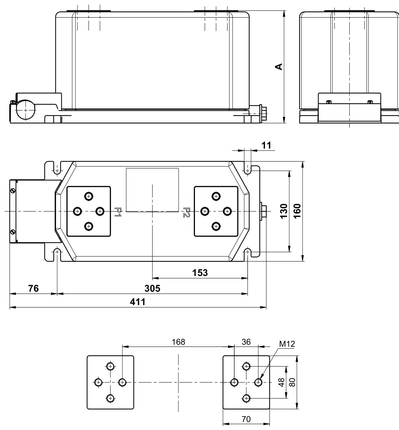
ABB KOFA12D3 Indoor current transformers
Technical parameters
Rated frequency: 50Hz and 60Hz.
Rated secondary current: 5 (1.2) A.
Rated load: 2.5, 5, 7.5, 10, 15, 20, 25, 30VA.
Accuracy levels: 0.2, 0.5, 1, 5P10, 5P20.
Mechanical strength of one terminal: 5kN.
Standards: Compliant with IEC, BS, ANSI and other standards, other data can be provided as required.
Structure and Design
Winding and packaging: The primary winding, iron core, and secondary winding are encapsulated by epoxy resin casting.
Secondary conductor:
The fixing screws on the light alloy base are also easily accessible from above.
The conduit used for the secondary conductor can be fixed at the U-shaped slot entrance of the secondary junction box to prevent the secondary conductor from entering the junction box through the entrance hole.
According to the order requirements, the junction box can be equipped with threaded entrances for cable terminal accessories.
One 2.5-10mm ² or two 2.5-6mm ² (one 2.5-6mm ² for three-phase transformers) conductors can be directly connected to the secondary terminal. The terminal cover can be sealed and the enclosure protection level is IP30.
Primary terminal: The primary terminal uses M12 screws, and the connection can be changed without removing the installed primary conductor.
Environmental and altitude requirements
Operating environment:
Suitable for indoor installation, IEC recommends an ambient temperature between -5 ℃ and+40 ℃, and can actually be used at temperatures as low as -40 ℃.
Transformers must prevent the deposition of large amounts of dust or similar pollutants, as well as avoid direct sunlight.
Altitude impact:
The altitude in mountainous areas may be higher than the elevation (1000m) used as a design standard in IEC standards.
The thin air in high-altitude areas can affect the cooling of transformers, as well as the creepage distance and air gap between ground and phases. In this case, the manufacturer should be consulted.
The issues of creepage distance and air gap can be solved by selecting transformer types designed for higher voltages. For the operating voltage used, it is best not to exceed the normal level of impulse test voltage (BIL level), as this may have a negative impact on the available output on the secondary side.
Insulation level
The insulation levels of KOFA models are 12/28/75kV, 17.5/38/95kV, and 24 (25)/50/125kV.
Preferred current transformer
Advantages:
The factory has prepared documents and materials for the most commonly used ratings, which can provide short delivery times for urgent needs.
Simplify the selection and ordering process by providing specific order codes for each standard current transformer.
Model examples: KOFA 12 D2 (12kV), KOFA 24 D2 (24kV).
Parameters: Secondary current of 5A, 2 iron cores, weights of 17kg and 19kg respectively, in compliance with international standard IEC 60044-1.
Ordering example: If the requirement is 6.6kV, in accordance with IEC 60044-1 standard, with a primary current of 100-200/5/5A, iron core 1 is 15VA, class 0.5, iron core 2 is 15VA, class 10P10, frequency 50Hz, the ordering code is KOFA 12 D2-L01.
Customized design transformer
One time and type selection table:
The table displays the available short-circuit strength and rated primary current for 12, 17.5, and 24kV, as well as the iron core selection symbol. The larger the iron core symbol, the smaller the size of the iron core and transformer. For transformers with two primary connections, this meter is suitable for lower rated currents, and at double the rated current, the thermal and dynamic intensity will also double.
The type selection table provides transformer types and weights corresponding to different numbers of iron cores at 12, 17.5, and 24kV.
Core selection table: Determine the core size based on rated load, accuracy level, etc.
Working principle
1、 Basic principles
Fundamentals of Electromagnetic Induction
When current passes through a winding, alternating magnetic flux is generated in the iron core. According to the law of electromagnetic induction, the secondary winding will induce electromotive force due to changes in magnetic flux, thereby generating current in a closed secondary circuit. The secondary current is directly proportional to the primary current, and the phase is basically the same. Through this proportional relationship, high current measurement and transformation can be achieved.
The relationship between primary and secondary sides
A winding with few turns (or even a single turn) is directly connected in series in the tested circuit, passing through a high current; The secondary winding has a large number of turns and is connected in series with measuring instruments or protective devices, with a small current (usually 5A or 1A).
2、 The support of key structures for principles
Winding and iron core design
Primary winding: usually a single conductor or a few turns, carrying the current of the tested main circuit and generating an alternating magnetic field.
Core: High permeability materials (such as silicon steel sheets) are used to concentrate magnetic field lines and improve electromagnetic induction efficiency. The change in magnetic flux directly affects the induced electromotive force on the secondary side.
Secondary winding: With a large number of turns, it outputs a secondary current proportional to the primary current through induced electromotive force for subsequent equipment use.
Insulation and encapsulation
As mentioned in the document, the KOFA series uses epoxy resin casting encapsulation for the primary winding, iron core, and secondary winding, which not only ensures electrical insulation but also fixes the structure to prevent iron core vibration from affecting electromagnetic induction stability.
3、 Job characteristics and application points
The relationship between accuracy and load
The load connected to the secondary side (such as instrument internal resistance, wire resistance, etc.) will affect the accuracy of the current transformer. The document mentions that the rated load range is 2.5-30VA, and excessive load may lead to increased errors. Therefore, it is necessary to select the appropriate rated load based on the parameters of the secondary equipment (such as accuracy levels of 0.2 and 0.5 corresponding to different load requirements).
For example, level 5P10 indicates that under rated load, when the primary current is 10 times the rated value, the composite error does not exceed 5%.
The impact of short-circuit current
When a short circuit occurs on the primary side, a high current will generate a strong magnetic field, which may cause the iron core to saturate and distort the secondary current. The document emphasizes the short-circuit strength parameters (such as short-time current I th, impulse current I dyn), and the design should ensure that the transformer can withstand the thermal and electrodynamic effects of short-circuit current to avoid damage or error exceeding the limit.
The danger of open circuit on the secondary side
The secondary winding must not be open circuited, otherwise when there is current on the primary side, the magnetic flux of the iron core will increase dramatically, and high voltage (up to thousands of volts) will be induced on the secondary side, endangering equipment and personnel safety, and possibly damaging the insulation of the transformer.
4、 Combining with KOFA series in the document
The Implementation of Principles in Structural Design
The KOFA series uses epoxy resin to encapsulate and fix windings and iron cores, reducing external interference and ensuring the stability of electromagnetic induction; The primary terminal is connected with M12 screws, which is easy to install and ensures good electrical contact, avoiding contact resistance affecting the conduction of primary current.
5、Parameter matching and application scenarios
The rated frequency of 50/60Hz is suitable for different power grid requirements, and the secondary current of 5A (1.2A) meets the standard measurement circuit requirements.
For high-altitude areas, by selecting models with higher voltage levels (such as 24kV instead of 12kV), increasing the creepage distance and air gap, preventing insulation breakdown, and ensuring the reliable application of electromagnetic induction principles in special environments.

- YOKOGAWA
- Reliance
- ADVANCED
- SEW
- ProSoft
- WATLOW
- Kongsberg
- FANUC
- VSD
- DCS
- PLC
- man-machine
- Covid-19
- Energy and Gender
- Energy Access
- Renewable Integration
- Energy Subsidies
- Energy and Water
- Net zero emission
- Energy Security
- Critical Minerals
- A-B
- petroleum
- Mine scale
- Sewage treatment
- cement
- architecture
- Industrial information
- New energy
- Automobile market
- electricity
- Construction site
- HIMA
- ABB
- Rockwell
- Schneider Modicon
- Siemens
- xYCOM
- Yaskawa
- Woodward
- BOSCH Rexroth
- MOOG
- General Electric
- American NI
- Rolls-Royce
- CTI
- Honeywell
- EMERSON
- MAN
- GE
- TRICONEX
- Control Wave
- ALSTOM
- AMAT
- STUDER
- KONGSBERG
- MOTOROLA
- DANAHER MOTION
- Bentley
- Galil
- EATON
- MOLEX
- Triconex
- DEIF
- B&W
- ZYGO
- Aerotech
- DANFOSS
- KOLLMORGEN
- Beijer
- Endress+Hauser
- schneider
- Foxboro
- KB
- REXROTH
- YAMAHA
- Johnson
- Westinghouse
- WAGO
- TOSHIBA
- TEKTRONIX
- BENDER
- BMCM
- SMC
- HITACHI
- HIRSCHMANN
- XP POWER
- Baldor
- Meggitt
- SHINKAWA
- Other Brands
- UniOP
- KUKA
- IBA
- Beckhoff
- ADLINK
-
Beckhoff CX1100-0910 - Power Supply Module
-
Beckhoff C5210-0010 - Communication Module C5210
-
BECKHOFF KL1352 - Bus Terminal SET OF 2 FREE FAST SHIP
-
Beckhoff EL3058 - 8 x analog input single ended 4...20mA 85惟 shunt 12bit
-
Beckoff CX1100-0920 - UPS Module 24VDC (US SELLER) * *
-
BECKHOFF C6920-0000 - C69200000 PLC Moudule
-
Beckhoff CX5120-0115 - CPU controller module CX5120-0115
-
Unknown 15F5C1E-Y50A - Of Frequency Converters
-
Beckhoff AX5118-0000-0200 - Servo Drive HTP0
-
BECKHOFF AX5106-0000-0200 - Servo Drive
-
Beckhoff CX5240-0175 - Module (free) #U2327D YG
-
Beckhoff CP6607-0001-0000 - Compact PC Panel Economy Installation Operator 5,7 "
-
Beckhoff EP3744-0041 - 2022 EP37440041 Module
-
Beckhoff CP6209-0001-0020 - 6.5" PC Touch Screen Control Panel 24VDC
-
Beckhoff CX9020-0111 - /U900 +8x+2xEL3121+1x EL9410+3xEL1008+1x EL2008 Set
-
Beckhoff C6525-1030-0050 - Industrial PC
-
Beckoff CX1100-0920 - UPS Module 24VDC (US SELLER)
-
Beckhoff CX5010-0120 - CX5010 Processor Intel Atom Z510 B24
-
Siemens 6FC5203-0AF04-1BA1 - Operation Panel
-
Beckhoff CX5230-0175 - / 000029724 Embedded PC / Industrial PC on Rail
-
Beckhoff CP3916-0000 - industrielles Anzeige- und Bedienterminal
-
BECKHOFF CX1500-M310 - CX1000-N000 CX1000-0011 CX1000-C00L CX1100-0002 PLC Module
-
Beckhoff EL1872 - 16-channel digital input terminal
-
BECKHOFF EP2318-0001 - module
-
Beckhoff CX9020-0110 - Basic CPU Module
-
Beckhoff EL2564 - EtherCAT Terminal, 4-channel LED output, 5鈥?8VDC, 4A, RGBW
-
Beckhoff CX5130-0155 - /000105637 Automation Embedded PC
-
B&R 400 - Power Control Panel Rev D0 24 VDC
-
Beckhoff CX2020-0155 - module
-
Beckhoff CX9020-0115 - PLC Module
-
BECKHOFF EL6695 - PLC EL 6695
-
BECKHOFF EL7047 - PLC Modules
-
Beckhoff CX1000-0012 - Control HW 2.2 + CX1500-M310 + CX1000-C00L + CX1100-0002+
-
Beckhoff C6920-1039-0030 - control cabinet industrial PC CPU Celeron 1.90 GHz, 2 cores
-
BECKHOFF CX1100-0910 - PLC Module#
-
Beckhoff IL2301-B318-0000 - Coupler Box 4 Channel Digital Input |
-
Beckhoff CX7080 - Module
-
Beckhoff C6930-0060 - Industrial PC
-
Beckhoff CP7902-1060-0000 - Touchscreen 15 " CP7902
-
beckhoff CX9020-0111 - Controller module or UPS
-
Beckhoff CX8091 - PLC Module CX8091
-
Beckhoff C6640-1008-0030 - Control Cabinet Industrial PC
-
BECKHOFF CX1100-0920 - module
-
Beckhoff C9900-M921 - see pictures
-
BECKHOFF CP6829-0001-0000 - Touch Panel
-
BECKHOFF C6930-0060 - Industrial Computer
-
BECKHOFF CX8050 - PLC module
-
Beckhoff CP6202-0021-0020 - Touch Screen #
-
BECKHOFF AM3031-0C20-0000 - SERVO MOTOR
-
Unknown BCH1302N11A1C - Servo motor
-
Beckhoff EL2502 - 2-channel pulse width output terminal
-
Beckhoff EL6731 - Profibus Master / *Rev: 0025
-
Beckhoff CP3918-0010 - Control Panel
-
BECKHOFF CP2915-0010 - [24 MONTH WARRANTY] Control Panel
-
Beckhoff AX5203-0000-0202 - Servo Drive
-
Schneider TSXDSY64T2K - PLC OUTPUT MODULE
-
Beckhoff EP4174-0002 - Module-
-
Beckhoff IL2302-B318-0000 - Profibus Box
-
Beckhoff CP6709-0001-0000 - Touchpanel
-
BECKHOFF CX2030-0123 - Controller
-
Beckhoff CX9020-0111 - Processor Module
-
Beckhoff CX1020-0000 - CX Basic CPU Module
-
Beckhoff AX2003-AS - Servo Drive HTP0
-
Beckhoff C6240-1052-0040 - 4-086-06-3073 Industrial Computer CB1052-0003
-
Beckhoff EL1918 - 8 xTwinSAFE Input
-
Beckhoff AM8072-0R20-0000 - Servomotor
-
BECKHOFF AM8021-1B21-0000 - servo motor #T882 YS
-
Beckhoff EL6224 - 4 X Terminal IO-LINK
-
Beckhoff CX5140-0135 - embedded PC with Intel Atom processor 4 GB HW 3.6
-
Beckhoff CP7201-1000-0000 - Panel PC #
-
Beckhoff CX5130-0121 - Embedded-PC 4GB CPU Module HW 2.5 Industrial PC
-
Beckhoff AM8022-0D41-1002 - Servomotor
-
BECKHOFF CX2030-0130 - Module
-
BECKHOFF EL1872 - 16-channel digital input terminal
-
Unknown GXMMW.A203P33 - 1pc encoder
-
Beckhoff EL6631-0000 - EtherCAT Terminal 2-Port EL 6631
-
BECKHOFF C6925-0030 - Industrial Computer
-
Beckhoff CX8190 - A Module
-
BECKHOFF CX2040-0135 - CX2040-0135/000000927 CPU BASE MODULE i7 2715QE 2.1GHz --
-
BECKHOFF KL6023-0000 - Wireless adapter
-
Saia Burgess PCD7.F700 - PCD7F700 Communication Module
-
Beckhoff CX5130-0112 - CPU Module
-
BECKHOFF CX1020-N010 - CX1020-N000 CX1020-0111 CX1100-0004 EL2008 EL3064 EL4004
-
Beckhoff EP1819-0021 - A Module
-
Beckhoff CX2030-0120 - / 4gb with CX2100 0004
-
B&R X20-XC-0292 - Automation Powerlink Ethernet Bus Controller Module
-
Beckhoff BK3110 - One PLC Module
-
BECKHOFF KL3222 - PLC Module
-
BECKHOFF CX1500-M310 - CX1000-N000 CX1000-0011 CX1000-C00L CX1100-0002 PLC MODULE
-
Beckhoff CP3918-0010 - Control Panel
-
Beckhoff CX2030-0100-1002 - /4GB + CX2100 + CX2550 + CX2500-0060 + SSD
-
Beckhoff EP1816-0008 - PLC Module
-
Beckhoff CX5130-0112 - Module
-
Beckhoff Cx1500-m750 - CPU Hw: 1.4
-
BECKHOFF AX5112-0000-0200 - AX511200000200 Servo Driver
-
Beckhoff EL3751 - EtherCAT Terminal 1 Channel Analog Input Multifunction 24 Bit
-
Beckhoff CX1100-0002 - Power Supply Module
-
Beckhoff CP3916-1016-0010 - Control Panel
-
BECKHOFF CX9001-1101 - #NAME?
-
Beckhoff EP3174-0002 - EtherCAT Box Module
-
Beckhoff C6030-0070 - servo drive
-
Beckhoff CX2020-0120 - /4GB CPU, CX2100-0904, 3x EL6900, EL1904, 16GB Memory
-
BECKHOFF C6110 - BOX-PC 113608
-
BECKHOFF EK1914 - module #P
-
Beckhoff C6140 - Ipox IP-4GVI63 + CH7009A_DVI_TV + SIEMENS A5E00369843 + WD800AAJB
-
Beckhoff CX5020-0111 - controller Good quality
-
BECKHOFF C6015-0010 - / 6559380 ULTRA-COMPACT INDUSTRIAL PC ()
-
Beckhoff AX5203-0000-0200 - PLC module
-
Beckhoff EL2872 - 16-channel digital output terminal
-
BECKHOFF C3640-0000 - Panel Industrial PC 100/240VAC 128MB E0122L
-
Beckhoff CX8031 - Module
-
Beckhoff CX5020-0120-1002 - PLC module#
-
Beckhoff C6140 - M845B + SIEMENS A5E00369843 + C9900_A159_1 + AUTOMATA CAN PCI 1N
-
BECKHOFF AX5112-0000-0200 - Servo Drive*ie
-
B&R ECPA42-01 - Analog Output Module 4-Channel, +/- 10V Output Signal, 20mA Max
-
Beckhoff EL6631-0010 - PLC Module
-
BECKHOFF C6930-0070 - CONTROL CABINET INDUSTRIAL PC
-
BECKHOFF AX5112-0000-0200 - AX511200000200 Servo Driver
-
BECKHOFF EK9000 - Programmable Logic Controller Module EK9000 EK9000
-
BECKHOFF C6920-1028-0000 - Industrial computer
-
Beckhoff CX2030-0120 - controller Module
-
Beckhoff BX8000-0000 - Bus Terminal Controller HW 4.4
-
B&R 3NC154.60-2 - Positioning Module#
-
BECKHOFF CX1020-0122 - PLC module
-
Beckhoff AM3032-0D40-0000 - Servo Motor
-
BECKHOFF CX5020-0111 - CPU Module CX5020-0111
-
Beckhoff CB1051 - G5 Motherboard
-
BECKHOFF KL2641 - 1-channel relay output terminal

K-JIANG

Add: Jimei North Road, Jimei District, Xiamen, Fujian, China
Tell:+86-15305925923