
K-WANG


KONGSBERG HMS 300 Helicopter Deck Monitoring System
KONGSBERG HMS 300 Helicopter Deck Monitoring System
Product basic information
Product positioning: HMS 300 is a takeoff and landing auxiliary monitoring system designed for helicopter decks on offshore ships. It is only used as a landing auxiliary equipment and cannot be used as a landing guide. Its core function is to monitor the acceleration, heave speed, tilt, roll, and pitch of the deck in real time, calculate key indicators based on meteorological/wind wave data, and improve helicopter takeoff and landing and passenger safety in complex environments.
Standard Compliance: Fully complies with the standards of the three major aviation regulatory agencies, namely UK CAP 437 (September 2018 edition), Norway NOROG 9.2, Brazil NORMAM-27, and is also compatible with Helideck Certification Agency (HCA) document revision 9b.
Cloud service expansion: The optional Kognifai cloud platform (paid service) enables real-time viewing of deck movement and meteorological data by both ship and shore sides, assisting helicopter flight planning.
Usage limitation premise: The system is suitable for offshore surface work vessels with linear acceleration<± 30m/s ² (± 3g) and angular velocity<± 75 °/s. The measurement range of the heave cycle is 1-25 seconds, and only the relative dynamic heave position is calculated.
System hardware and composition
The HMS 300 is a dual module core architecture (processing unit+EDGE/HMI unit), connected via Ethernet and equipped with various sensors and auxiliary devices. The hardware composition and core functions are shown in the table below:
Equipment Type Core Component Function Description
The core processing unit independently runs critical calculations, receives sensor data, calculates MSI/WSI/SHR, and determines takeoff and landing safety
The human-machine interaction unit EDGE/HMI displays data in a visual form and supports mouse/keyboard operations. Some configurations require dual Ethernet connections for dual IOT units
Inertial sensors IMU (MRU E/H/5/5+, MGC R2/R3) accurately monitor the ship's motion and acceleration at the center of the deck, serving as the core source of motion data
Environmental sensors collect data on wind speed, wind direction, temperature and humidity, air pressure, wave height, wave period, seawater temperature, etc
Auxiliary equipment relay lights/status lights/junction box relay lights synchronize system status colors, and the junction box realizes the line connection between sensors and core units
Network equipment GSN routers/switches enable network communication between various units and sensors, supporting data transmission
Key hardware requirements: When meeting the CAP 437 standard, wind speed data needs to be output at 4Hz and a dedicated wind speed sensor needs to be separately configured; The processing unit integrates an LCD display screen and buttons, which are only used for system status diagnosis and internal menu access.
Core operating procedures
The system operation needs to follow standardized procedures, including power on/off/restart, standard selection, mode switching, report generation, etc. The key operating steps and requirements are as follows:
Power on/off and restart
Power on: First turn on the monitor → Processing unit (power button under the left cover of the front panel) → EDGE/HMI unit, enter the default password "operator user", and the system will automatically enter the operation interface, provided that the IMU and weather sensors are powered on normally and all cables are connected properly;
Shutdown: It is necessary to control the shutdown through the system menu (Setup → Processing Unit Control → PU Shutdown, operate the HMI unit in the same way), and then turn off the physical power. It is forbidden to directly power off the power;
Restart: Select "Restart" from the menu "Setup" → "Processing Unit/HMI Control". After confirmation, the system will automatically complete. After restarting, you need to re-enter your password.
Basic configuration operation
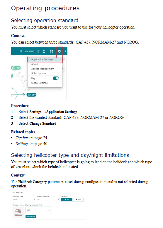
Operation standard selection: Settings → Application Settings, select CAP 437/NOLOG/NORMAM-27, click Change Standard to take effect;
Helicopter and takeoff and landing settings: Select the helicopter type (CAT A/B) and day and night takeoff and landing restrictions in the User inputs. The deck category is a configuration item and cannot be modified during operation;
Display and device control: Select the display palette (Day/Dusk, suitable for night operation in dusk mode, does not affect night vision) in Settings to remotely turn on and off the helicopter deck relay lights. After turning off, the interface will display a red warning.
CAP 437 Exclusive Mode Switching
CAP 437 is the only standard that supports * * Pre landing/On deck * * dual-mode, and switching must strictly follow the process:
Pre landing → Deck: After the pilot reports the helicopter heading, enter the three digit magnetic heading in User inputs and click Enter Heading → Confirm to complete the mode switch;
Deck → Pre Landing: After the helicopter takes off, click Helicopter Departed → Confirm in User inputs to restore pre landing mode.
Meteorological/Deck Report Generation
Before takeoff and landing, standardized reports need to be generated. CAP 437/NORMAM-27 is the meteorological report, and NOROG is the deck report (with more concise content). The process is: sidebar HMS/Report ->write an email ->fill in the required fields with red asterisks ->Create report&screenshot ->Generate report (generate PDF+current interface screenshot) ->Preview and send ->send after checking attachments.
User Interface and Menu System
Operating principle: By using the mouse and keyboard of EDGE/HMI unit, the cursor will automatically hide after about 1 minute of inactivity, and can be restored by moving the mouse; The LCD+buttons of the processing unit are only used for system diagnosis and do not participate in routine operations.
Interface layout: The core structure consists of a top bar, side bars, and multiple display views
Top bar: displays the current operating standard/mode, vessel name/location, UTC time, network service quality, user configuration, application/settings menu, supports hiding/restoring;
Sidebar: Supports CAP 437 mode switching, report generation, expandable/foldable;
Display view: divided into general view (supported by all standards) and standard exclusive view, the general view includes user input, status, deck wind and heading, meteorological data, and operation status; Exclusive views such as RWD relative wind direction restrictions for CAP 437, motion summary/historical views for NOROG, etc.
Core menu system: The four major menus on the right side of the top bar cover all operation and configuration requirements, with the following functions:
Alarms: List the latest 20 alarm notifications of the system to achieve fault warning;
My profile: supports user information editing, password modification, and logout, with three levels of permissions: * * operator (default), support engineer (advanced configuration), and observer (read-only) * *;
Application menu: includes data analysis PU Portal、 Testing pages and other applications only support engineer access permissions;
Settings: Implement core configurations such as standard switching, unit selection, relay light control, unit restart/shutdown, and display palette settings.
Status indication rules: System status is distinguished by light color, CAP 437 is red/yellow/blue tri color, NOROG/NORMAM-27 is red/green dual color, relay light is synchronized with interface light color, and the core status is defined as follows:
Red: Deck stability exceeds landing limit (always on); Relative wind direction exceeds the limit (flash, only CAP 437 deck mode);
Yellow/Amber: MSI/WSI exceeds the limit (constantly on, it is recommended to modify the operation process); The relative wind direction is about to exceed the limit (flash, only CAP 437 deck mode);
Blue: safe landing (always on, only CAP 437 pre landing mode); The relative wind direction is within the limit (slow flashing, only CAP 437 deck mode);
Green: Helicopter can take off and land (always on, only NOROG/NORMAM-27).
System maintenance and troubleshooting
The maintenance of HMS 300 is divided into four categories: troubleshooting, regular maintenance, sensor calibration, and component replacement. The core requirements and processes are as follows. It is prohibited to disassemble the processing unit, EDGE/HMI unit, and IMU module without authorization, otherwise the warranty will be invalidated:
Common troubleshooting
System faults can be determined through the operation status view and processing unit LED indicator lights. The core faults and processing procedures are shown in the following table:
Troubleshooting and Handling Process
Without power supply, check the power connection → repeatedly switch the power button of the processing unit (eliminate poor contact) → check the fuse inside the power connector
No mouse cursor, no processing required, can be restored by moving the mouse (automatically hidden after 1 minute of inactivity)
The windless data system defaults to using true wind data. If true wind is interrupted, the system needs to be restarted to switch to relative wind data
IMU fault (red) check Port Monitor → confirm IMU cable connection → check junction box fuse; If there is a malfunction, return to the factory for repair
IMU data is unstable (yellow). Check the grounding of the IMU cable shielding layer and confirm the terminal connection of the junction box; If the fault persists, return to the factory for repair
regular maintenance
Cleaning of air intake of processing unit: The air intake filter should be cleaned at least once every 6 months (adjusted according to the ambient air quality), cleaned with mild detergent or vacuum cleaner, and replaced if it is severely dirty;
Software upgrade: Completed through the Kangshibo exclusive portal with official remote support, users are not allowed to upgrade on their own.
Sensor calibration and replacement
Sensor calibration needs to be performed according to the model/component, and the core requirements are as follows:
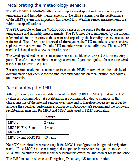
Meteorological Sensor (WXT520/530): The PTU module (temperature, humidity/air pressure) is affected by chemicals in the air and needs to be replaced every 3 years (non calibratable). The wind speed and direction sensor has no moving parts and does not require calibration/replacement;
IMU module (MRU/MGC): Due to changes in internal sensor characteristics, regular factory calibration is required. The calibration cycle is differentiated by model: MRU 3 is 2 years, MRU H/E/5+, MGC R2 is 5 years, MRU 5+, MGC R3 is 10 years; If MGC is configured in integrated navigation mode, calibration is not required (automatic correction of accelerometer drift).
Component replacement and return to factory
Spare parts installation: The spare processing unit can backup/restore the original system configuration through a USB flash drive (Tools → Copy/Restore configuration). If the original hard drive fails, it needs to be reconfigured according to the installation manual;
Return to factory repair: processing unit, EDGE/HMI unit IMU、 Meteorological sensors and other faulty components need to be returned to the factory. Contact the official to obtain an RMA number (Return Merchandise Authorization) and indicate the number during transportation; When IMU returns to the factory, only remove the sensor body and keep the installation bracket.
Product usage and warranty restrictions
Usage restriction: It is only used as a helicopter landing aid and cannot be used as a landing guide. Unauthorized use may result in equipment damage/personnel injury;
Export restrictions: IMU modules (MRU/MGC) require a license for export and are shipped from Norway. Due to restrictions imposed by the Norwegian Ministry of Foreign Affairs and the US EAR regulations, Konigsberg's export license does not allow users to re export/re export;
Warranty limitation: Any modification or alteration without explicit approval from Kangshibo will result in the expiration of the warranty; The warranty only covers system maintenance and does not assume indirect losses (such as loss of profits or other system damages); Malfunctions caused by incorrect power connection or improper operation are not covered by the warranty;
Network Security: The system does not have built-in network security software and does not protect against viruses/malicious access. Users are required to develop and implement their own network security policies, and Konigsberg does not assume any responsibility for network security.
- YOKOGAWA
- Reliance
- ADVANCED
- SEW
- ProSoft
- WATLOW
- Kongsberg
- FANUC
- VSD
- DCS
- PLC
- man-machine
- Covid-19
- Energy and Gender
- Energy Access
- Renewable Integration
- Energy Subsidies
- Energy and Water
- Net zero emission
- Energy Security
- Critical Minerals
- A-B
- petroleum
- Mine scale
- Sewage treatment
- cement
- architecture
- Industrial information
- New energy
- Automobile market
- electricity
- Construction site
- HIMA
- ABB
- Rockwell
- Schneider Modicon
- Siemens
- xYCOM
- Yaskawa
- Woodward
- BOSCH Rexroth
- MOOG
- General Electric
- American NI
- Rolls-Royce
- CTI
- Honeywell
- EMERSON
- MAN
- GE
- TRICONEX
- Control Wave
- ALSTOM
- AMAT
- STUDER
- KONGSBERG
- MOTOROLA
- DANAHER MOTION
- Bentley
- Galil
- EATON
- MOLEX
- Triconex
- DEIF
- B&W
- ZYGO
- Aerotech
- DANFOSS
- KOLLMORGEN
- Beijer
- Endress+Hauser
- schneider
- Foxboro
- KB
- REXROTH
- YAMAHA
- Johnson
- Westinghouse
- WAGO
- TOSHIBA
- TEKTRONIX
- BENDER
- BMCM
- SMC
- HITACHI
- HIRSCHMANN
- XP POWER
- Baldor
- Meggitt
- SHINKAWA
- Other Brands
- UniOP
- KUKA
- IBA
- Beckhoff
-
ADLINK CPCI-6860A - 51-31310-OB10 industrial motherboard CompactPCI SBC
-
ADLINK AmITX-SL-G-H110 - 51-7A104-0A30 Mini-ITX Industrial Motherboard
-
ADLINK PXI-2005-003 - CPCI Industrial PC Data Acquisition Card Multi-Function DAQ
-
ADLINK DININ-814M - 51-14032-0A3D SCSI-100P cable connection Interface Terminal Board
-
ADLINK CPCI-3920NA/C2D15/M1G - 3U CompactPCI Intel Core 2 Duo Single Board Computer
-
ADLINK PCIE-8560 - 51-18014-0A20 Communication Card High Speed DAQ
-
ADLINK PCI-C154+ - Motion Control Card 4-axis Motion Controller Board
-
ADLINK PCI-RTV24 - image capture card Analog Video Frame Grabber
-
ADLINK NuPRO-842LV/P - 51-41360-0B30 Industrial Motherboard CPU Board
-
ADLINK cBP-3208/3208R - CPCI Board 3U 8-Slot CompactPCI Backplane
-
ADLINK PCI-8164 - 4-Axis Motion Controller PCI Card 51-12406-0A40
-
ADLINK PCIe-GIE64+ - 4-CH GigE Vision PoE+ Frame Grabber Video Capture Card
-
ADLINK CPCI-6860 / 6860A - CompactPCI Dual Xeon Single Board Computer
-
ADLINK IEC-915GV - REV 1.1 Industrial motherboard CPU Board
-
ADLINK ND-6520 - Technology RS-232 to RS-422RS-485 Converter NuDAM Module
-
ADLINK RTV-24 / PCI-MP4S - 51-12519-1C30 4-Channel Real Time Video Capture Board
-
ADLINK cPCI-6910 / cPCI-6910AM/M1G - cPCI-6910AM/DXL16/M1G/S80G(G)-3120 BOARD CompactPCI SBC
-
ADLINK NUPRO-A40H - Linghua 51-41807-1A30 Industrial Control Computer Motherboard
-
ADLINK USB-3488A - USB to GPIB INTERFACE USB-3488A(G) Controller Module
-
ADLINK PCI-8134A - motion control card 4-Axis Controller Card
-
ADLINK PCI-7432 - Board 32-Channel input / 32-output Isolated Digital I/O PCI Card
-
ADLINK PCI-8134A - 51-12421-0A10 motion controller card tested
-
ADLINK LPCIe-7230 - 32 CH Isolated Input/output Card 2 Interrupts Low Profile PCIe
-
ADLINK NuPRO-E340 - industrial computer motherboard 51-47807-0A30 PICMG 1.3 SHB
-
ADLINK PCI-7434 - High-speed Digital Acquisition Card 64-CH Isolated DO Card
-
ADLINK NuPRO-E330 - 51-41805-0A20 Indsutrial Board SHB Single Board Computer
-
ADLINK PCI-7248 - OPTO-22 48 CHANNEL DIO DIGITAL TTL/DTL I/O 51-12006-0A40 GP
-
ADLINK PCI-8134 - Motion control card 4-Axis Controller Card
-
ADLINK AMP-208C - Movimiento Control Tarjeta 51-12420-1A20 W/Expansión & Breakout
-
ADLINK PCI-8164 - 51-12406-0A40 PCB Board 4-Axis Motion Controller Card
-
ADLINK DIN-68Y-SGII / DIN-68M-J3A - Terminal Board Connector Interface Block
-
ADLINK PCIe-7432 - Technology 51-18402-0A10 PCIe Card With High Input Range
-
ADLINK PCI-8144 / PCI-8144N - Motion control card 4-Axis Stepper Controller Card
-
ADLINK HSL-HUB3/REPEATER - HIGH SPEED LINK EXTENSION MODULES Distributed Hub Module
-
ADLINK ND-6017 - Data Logging + Acquisition 8CH A/D input Mod NuDAM Module
-
ADLINK LPCIe-7250 - data acquisition card Low Profile 8-CH Relay Output Card
-
ADLINK PCI-7432 - I/O card 64-CH Isolated Digital Input Output PCI Card
-
ADLINK IMB-M43H - industrial control computer motherboard Q87 Chip Micro-ATX
-
ADLINK MP-C154 - Motion control Card 4-Axis Motion Controller Board
-
ADLINK PCI-RTV24 - image capture card Video Frame Grabber Card
-
ADLINK PCI-7250 - 8-CH Relay Output & 8-CH Isolated DI Card
-
ADLINK PCI-6308V - 8-CH 12-Bit Isolated Analog Output PCI Card PCB-I-E-1148=6EX2
-
ADLINK PCI-7248 - capture card 48-CH Opto-22 Compatible DIO Card
-
ADLINK HSL-AI16A02-M-VV - Analog Input Output Distributed Module
-
ADLINK NuPRO-A301 - Rev:1.4 NUPRO-A301 PICMG Full-Size Single Board Computer
-
ADLINK PCI-6208V-GL - 8-CH Voltage Analog Output PCI Card
-
ADLINK PCI-8134A - 51-12421-0A10 4-Axis Motion Controller Card
-
ADLINK MNET-S23 - TECHNOLOGY MNET S23 - SERVO DRIVER CONTROL MODULE
-
ADLINK M-342 - ATX I3 I5 I7 Q67 Industrial Motherboard
-
ADLINK NUPRO-780 - Industrial Motherboard CPU Board PICMG SBC
-
ADLINK MP-C154 / MP-C152 - 4-Axis Motion Control Card Pulse-Train Controller
-
ADLINK NuPRO-935A/LV10B0 - Motherboard 51-41802-0A10 GP w/RAM Industrial Control Board
-
ADLINK MP-C154 - Motion control card 4-Axis Motion Controller Mainboard
-
ADLINK PCI-7250 - PCI Acquisition Card 8-CH Relay Output Isolated DI Card
-
ADLINK ACL-7124 - Technology Inc.24 DIO Card Digital Input Output Card
-
ADLINK PCI-8554 A2 - Timer/Counter Data Acquisition Card
-
ADLINK DIN-825-GP4 - Terminal Block Interface Board Breakout Module
-
ADLINK NuPR0-761 - REV:1.1 Industrial motherboard Full-Size PICMG SBC
-
ADLINK MXE-1401/M8G (G) - Matrix Fanless Embedded Computer Industrial PC
-
ADLINK HSL-DI16DO16-UD-NN - Digital 16 Channel I/O Mod Distributed I/O Module
-
ADLINK ND6520 - NUDAM INTELLIGENT DA&C MODULE RS232-RS-422/RS485 CONVERTOR
-
ADLINK NUPRO-761 - REV:1.1 Industrial Motherboard CPU Board
-
ADLINK AMP-208C - Motion Control Card 51-12420-1A20 DSP-based 8-axis
-
ADLINK NuPRO-A301REV 1.4 - with packaging industrial computer motherboard PICMG SBC
-
ADLINK PCM-9112+ - 51-12300-0A2 industrial motherboard Multi-Function DAQ PC/104 Module
-
ADLINK PCM-7250+ - 8-CH Relay Outputs & 8-CH Isolated DI Module PC/104
-
ADLINK PCI-RTV24 - Image capture card Analog Video Frame Grabber
-
ADLINK PCI-8134 - Motion Controller PCI Card 4-Axis Controller Board
-
ADLINK PCI-7432 - Isolated Digital I/O PCI Card
-
ADLINK PCI-8554 A2 - acquisition card Timer/Counter Card
-
ADLINK PCI-8132 - Rev.A2 2-Axis Servo & Stepper Motion Controller Card
-
ADLINK PCI-8132 - Data Acquisition card 2-Axis Motion Controller Card
-
ADLINK EBP-13E4 - 51-46703-0A30 Industrial Backplane Board Passive Backplane
-
ADLINK PCI-800L - Electronic Card Interface Controller Card
-
ADLINK PCIe-GIE72 - 51-18531-0A10 PCB Board GigE Vision Frame Grabber
-
ADLINK DAQ-2010(G)-OOBO - Simultaneous-Sampling Multi-Function DAQ Card
-
ADLINK PCI-9112 - REV.B1 Multifunction DAQ Card Data Acquisition Card
-
ADLINK PCI-7230 - 51-12003-DA60 32-CH Isolated Digital I/O Card
-
ADLINK PCI-7432 - Data Acquisition Card Isolated Digital I/O PCI Card
-
ADLINK ETX-AT-N270-18/LXE - 51-71111-0A20 ETX CPU Module Motherboard
-
ADLINK HSL-DI32-UD-N - DIGITAL INPUT 32 POINTS MODULE Distributed I/O
-
ADLINK AMP-204C - Motion Control card DSP-Based 4-Axis Advanced Controller
-
ADLINK MNET-4XMOG-0050 - Four-axis Motion Controller Distributed Motion Module
-
ADLINK AMP-204C - Motion control card DSP-Based 4-Axis Pulse-Train Controller
-
ADLINK PCI-7442 - Switch card 64-Channel Datalogging & Acquisition Card
-
ADLINK M-302 - Industrial control motherboard ATX PC Board
-
ADLINK NUPRO-852 / NUPRO-852LV - Industrial motherboard Single Board Computer
-
ADLINK PCI-8134 - REV.B1. 4-Axis Motion Controller Card
-
ADLINK PCI-GIE62 + - 51-18502-0A20 2-CH GigE Vision Frame Grabber PoE Card
-
ADLINK PCI-MPG24 - 51-12523-0B20 MPEG4 Card Video Compression Hardware
-
ADLINK HSL-TB32-M-DIN - 32-CH I/O TERMINAL W/ HSL-AI16AO2-M-VV MODULE
-
ADLINK PCI-M114-GL - PCB Ver 2.1 Motion Controller Axis Card
-
ADLINK IMB-M40H - SYM76996H61 motherboard Industrial Computer Mainboard
-
ADLINK NUPRO-A40H - 51-41807-1A20 industrial control motherboard H61 Chip
-
ADLINK PCI-M114-GL - Axis Card Data Acquisition Card PCB VER2.2 Motion Controller
-
ADLINK PCI-8134 - Motion Controller PCI Card 4-Axis Controller Board
-
ADLINK PCI-8102 - Motion control card 2-Axis Servo & Stepper Controller
-
ADLINK NuPRO-841REV:3.0 - motherboard Industrial Control PC Board
-
ADLINK HSL-TB32-U-DIN REV A1 - Breakout Terminal Board Field I/O Module
-
ADLINK AMP-204C - Motion Control card DSP-Based 4-Axis Pulse-Train Controller
-
ADLINK NUPRO-A40H - 51-41807-1A20 industrial control motherboard H61 PC Board
-
ADLINK PCI-6308A / PCI-6308V - 51-12202-0A50 Isolated Analog Output Card
-
ADLINK AMP-204C - DSP-Based 4-Axis Advanced Pulse-Train Motion Controller
-
ADLINK PCI-7434 - Technology 64-Channel Isolated Digital I/O PCI Cards
-
ADLINK CPCI-6840 / CPCI-6840V / PM16/M1G-12G0 - CompactPCI Single Board Computer CPU Module
-
ADLINK PCIE-GIE74 - Motherboard Video Capture Card 51-18531-0A10 Frame Grabber
-
ADLINK NuPRO-E330 - industrial computer equipment motherboard Control Mainboard
-
ADLINK AMP-208C / 51-12420-1A20 - Motion Control Card W/ Expansion & Breakout Board
-
ADLINK HPCI-14S12U - industrial computer baseboard Passive Backplane 14 Slots
-
ADLINK PCI-8164 - 4-Axis Motion Controller PCI Card W/ 1x Cable, 1x Breakout Box
-
ADLINK PCIe-RTV24 - 51-18016-0A20 Image Acquisition Video Capture Card
-
ADLINK M-342 - 5 PCI ATX Motherboard Industrial PC Mainboard
-
ADLINK PCI-FIW64 - 4/2 Channel IEEE1394B Image Capture Card FireWire Frame Grabber
-
ADLINK PCI-7432 - digital IO card 64-CH Isolated Digital Input Output Card
-
ADLINK 51-12001-0C20 - Circuit Board PCI-7200 Data Acquisition Controller Card
-
ADLINK PXI-3920 - PXI 3U cPCI Industrial Controller Embedded System CPU Board
-
ADLINK NuPRO-841REV:2.0 - motherboard Industrial Control PC Board
-
ADLINK NuPro-E330 - 51-41805-0A20 PCB Industrial Control Computer Motherboard
-
ADLINK PCI-RTV24 - Image capture card Analog Video Frame Grabber
-
ADLINK PCI-7442 - Switch card 64-Channel Datalogging & Acquisition Card
-
ADLINK HPX-13S4 - device baseboard Passive Backplane Riser Card
-
ADLINK PCI-9112 REV A.1 - Multi Function DA&C Board Data Acquisition Card
-
ADLINK PCI-7248 - 51-12006-0A40 Card Control 48-CH Digital I/O Module
-
ADLINK CPCI-6860 / 6860A - motherboard CompactPCI Dual Xeon Single Board Computer
-
ADLINK DPAC-3020-11(G) - Embedded PC Automation Controller Machine Control Board
-
ADLINK NuPRO-841 REV:1.0 - industrial control motherboard CPU Board
-
ADLINK MNET-4XMOG-0050 - Four-axis Motion Controller MNET Motion Control Card
-
ADLINK ETX-AT-N270-18/LXE - 51-71111-0A20 ETX CPU Module Motherboard

K-JIANG

Add: Jimei North Road, Jimei District, Xiamen, Fujian, China
Tell:+86-15305925923