
K-WANG


WAGO series molded case circuit breaker (MCCB)
Core function of the product: As a key protective component of low-voltage distribution networks, it can detect and disconnect faults such as overload, short circuit, and grounding faults, and protect the safety of circuits and electrical equipment.
WAGO series molded case circuit breaker (MCCB)
Product Scope and Manual Positioning
1. Product details for adaptation
Clearly cover the specific series of WAGO molded case circuit breakers, list the core compatible models (including sub models with different rated currents and breaking capacity levels), and label the product application scenario boundaries (such as industrial distribution, building power supply, and other low-voltage distribution systems).
Core function of the product: As a key protective component of low-voltage distribution networks, it can detect and disconnect faults such as overload, short circuit, and grounding faults, and protect the safety of circuits and electrical equipment.
2. Core purpose of the manual
Target audience: Electrical installation personnel, maintenance technicians, equipment management personnel (with corresponding electrical qualifications).
Core value: Provide standardized and compliant operating basis, avoid equipment damage, electric shock, fire and other safety risks caused by installation errors, improper operation, and maintenance deficiencies, while ensuring stable product performance.
Important statement: The manual specifies the minimum requirements for safe use of the product, which must be implemented in conjunction with the on-site distribution system specifications and local electrical regulations; After the manual is revised, the latest version shall prevail, and the content of the old version shall automatically become invalid.
Safety Warning and Basic Requirements
1. Core security warning
Electrical safety: All operations must be carried out after power failure, and it is necessary to confirm that there is no residual voltage in the circuit (using professional electrical inspection tools). Live installation, wiring, or disassembly are prohibited.
Protection requirements: Insulated gloves, goggles and other protective equipment should be worn during operation to avoid injuries caused by electric arc burns and metal debris splashes.
Prohibited scenarios: It is strictly prohibited to modify the core components of circuit breakers (such as release devices and arc extinguishing chambers); It is strictly prohibited to use beyond the rated parameters (current, voltage, breaking capacity); It is strictly prohibited to operate in non-standard environments such as humidity, corrosion, and excessive dust.
Responsibility statement: The manufacturer shall not be held responsible for any equipment malfunctions or safety accidents caused by failure to comply with the manual requirements.
2. Basic usage prerequisites
Personnel qualifications: Operators and maintenance personnel must have low-voltage electrical operation qualifications, be familiar with the principles of power distribution systems and the working mechanism of circuit breakers.
Environmental requirements: Clearly define the environmental conditions for product operation, with a temperature range typically between -5 ° C and 40 ° C, humidity ≤ 95% (no condensation), and altitude ≤ 2000m (reduced capacity is required for use beyond altitude); Keep away from flammable, explosive, strong magnetic fields, and strong vibration sources.
Equipment inspection: Before installation, it is necessary to confirm that the appearance of the circuit breaker is not damaged, the accessories are complete (such as release, operating handle, wiring terminal), and the product nameplate parameters are consistent with the actual usage requirements.
Installation specifications and operating procedures
1. Preparation before installation
Tool preparation: Professional tools such as torque wrenches, crimping pliers, and insulation stripping pliers are required, and the insulation performance of the tools must meet safety standards.
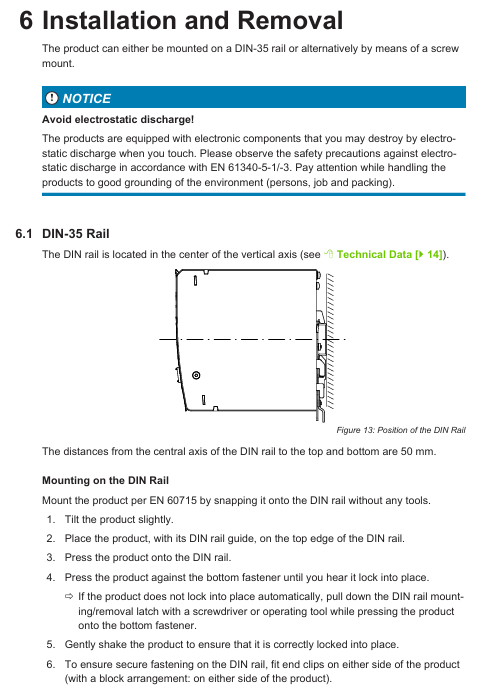
On site inspection: Confirm that the installation plate at the installation location has sufficient strength (able to withstand the weight of the circuit breaker and the electric force during short circuit), and that the installation surface is flat and free of debris; The specifications of the distribution line should match the rated current of the circuit breaker (the wire cross-section and material should meet the requirements).
2. Specific installation process
Fixed method: The circuit breaker is fixed to the mounting plate with bolts, and the bolt torque must comply with the manual regulations (different models correspond to different torque values) to avoid loosening and vibration during operation.
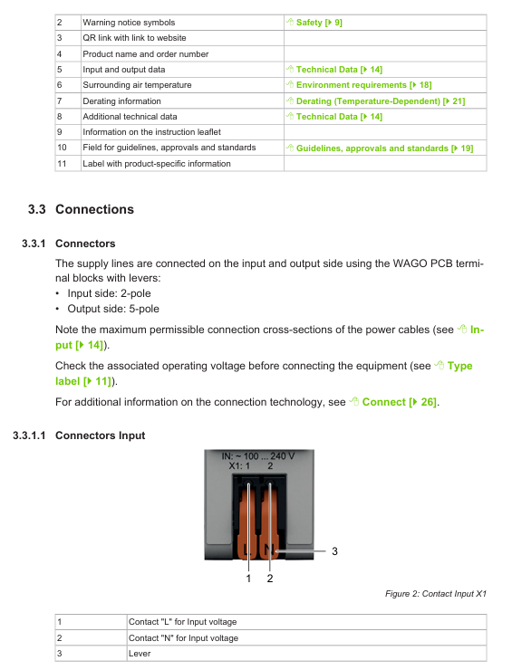
Wiring requirements:
The direction of incoming and outgoing wires should follow the manual markings (reverse wiring is not allowed), and the length of wire stripping should match the depth of the terminal to avoid short circuits caused by exposed conductors being too long.
When tightening the wiring terminals, it is necessary to operate according to the specified torque to prevent excessive looseness from causing excessive contact resistance and heating, or excessive tightening from damaging the terminals.
Multi core wires require the use of crimping terminals, and it is prohibited to directly insert multi stranded wires into the terminal holes.
Attachment installation: If auxiliary contacts, undervoltage release and other accessories need to be installed, they must be connected correctly according to the wiring diagram to ensure that the accessories match the main function of the circuit breaker. After the wiring is completed, the reliability of the accessory action needs to be checked.
3. Check after installation
Mechanical inspection: Manually operate the circuit breaker to close and open, and the action should be smooth without any jamming. The handle position should be clear (with clear identification of the closing, opening, and energy storage status).
Electrical inspection: Confirm that the wiring is not loose, the phase sequence is correct, and the insulation resistance test is qualified (using a 500V megohmmeter, insulation resistance value ≥ 1M Ω).
4. Operating instructions
Closing operation: After ensuring that there are no faults in the circuit, manually turn the handle to the "closing" position, and hear a "click" sound to indicate that the closing is in place; If equipped with an electric operating mechanism, press the control button to complete the closing and observe that the mechanism operates normally.
Opening operation: When opening normally, turn the handle to the "opening" position. After the fault is opened, the fault needs to be checked first, and the release device needs to be reset before closing.
Release adjustment:
Overload release: Adjust the set current within the range specified in the manual based on the load characteristics of the line (not exceeding the rated current of the circuit breaker) to ensure delayed release in case of overload.
Short circuit release: The instantaneous release setting current is adjusted according to the calculated value of the short-circuit current in the distribution system, ensuring quick disconnection during a short circuit and avoiding the expansion of the fault.
Ground fault release (if equipped): Adjust the ground fault action current and delay, and coordinate with system protection.
Maintenance and upkeep requirements
1. Daily maintenance cycle
Regular inspection: Under normal operating conditions, conduct a routine inspection every 6 months; In harsh environments (high dust, high humidity, frequent operation), reduce to once every 3 months.
Annual maintenance: Conduct comprehensive maintenance once a year, synchronized with power outage maintenance of the distribution system.
2. Maintain projects and operations
Appearance inspection: Check whether the circuit breaker casing and operating handle are damaged or discolored, and whether there are any signs of heating on the terminals (such as oxidation or burnt black).
Mechanical performance inspection: Operate the closing and opening of the circuit several times to check whether the action is smooth and whether the tripping mechanism is sensitive; The energy storage mechanism (if any) can reliably maintain energy after storage and act quickly when released.
Electrical performance inspection:
Measure insulation resistance to ensure there is no insulation aging or moisture damage.
To check the accuracy of the release action, it can be tested by simulating overload and short circuit conditions (professional equipment is required, and blind testing on site is prohibited).
Cleaning requirements: Use a dry brush or compressed air (pressure ≤ 0.4MPa) to remove dust from the surface and terminals of the circuit breaker. It is prohibited to use wet cloths or organic solvents for cleaning.
3. Maintain taboos
Non professionals are prohibited from disassembling core components such as circuit breakers, arc extinguishing chambers, and release devices. Disassembling them will cause the product to lose its protective function and cannot guarantee sealing.
It is prohibited to change the setting parameters of the release during maintenance (unless there is a clear load adjustment requirement and it is operated by professional personnel).
During the maintenance process, it is necessary to cut off power throughout the entire process and hang a "under maintenance, no closing" sign to prevent others from making mistakes.
Troubleshooting and Solutions
1. Common faults and their solutions
Possible causes and solutions for the fault phenomenon
Unable to close 1. The fault has not been resolved and the release has not been reset; 2. The operating mechanism is stuck; 3. The auxiliary contacts have not been reset; 4. Power failure of electric operating mechanism: 1. Check for short circuit and overload faults, and manually reset the release; 2. Check if there are any foreign objects in the organization, clean them and test them; 3. Check the auxiliary contact wiring and repair the poor contact of the contacts; 4. Check the power supply of the operating mechanism and restore power supply
Wrong tripping (tripping when there is no fault) 1. Overloaded tripping device setting current is too low; 2. There is harmonic interference in the line; 3. The release device is damaged; 4. Excessive ambient temperature leads to misoperation of the release device. 1. Adjust the setting current again according to the actual load current; 2. Investigate harmonic sources and install filtering devices if necessary; 3. Replace the damaged release device; 4. Improve ventilation conditions and reduce environmental temperature
Opening failure: 1. Operating mechanism failure (such as spring failure or jamming); 2. The release device is damaged; 3. Loose wiring causes the mechanism to fail to interlock. 1. Disassemble and inspect the mechanism, replace the faulty spring, or clean any stuck foreign objects; 2. Replace the release device; 3. Tighten the wiring to ensure normal linkage of the mechanism
Terminal heating: 1. Loose wiring; 2. The cross-sectional area of the wire is too small; 3. Terminal oxidation or poor contact: 1. Re tighten the terminal according to the specified torque; 2. Replace the wires that meet the requirements; 3. Clean the terminal oxide layer and replace the terminal if necessary
Abnormal noise of circuit breaker: 1. Loose installation leads to vibration; 2. Wear or looseness of institutional components; 3. Electromagnetic noise during overload operation: 1. Re tighten the circuit breaker to enhance installation stability; 2. Check the components of the mechanism, replace worn parts, and tighten loose parts; 3. Investigate the cause of overload and reduce the load to the rated range
2. Fault handling principles
Before the fault is thoroughly investigated, it is forbidden to forcefully close the switch to avoid expanding the scope of the fault or causing safety accidents.
If the circuit breaker experiences serious malfunctions such as damage to the arc extinguishing chamber, deformation of the outer shell, or burning of internal parts, maintenance is prohibited and the circuit breaker of the same model must be replaced directly.
After troubleshooting, action testing and electrical performance testing are required to confirm that there are no issues before resuming operation.
Technical parameters and compliance statement
1. Core technical parameters
Rated parameters: Clearly define key parameters such as the rated voltage (e.g. AC 400V/690V), rated current (e.g. 100A~630A), rated breaking capacity (e.g. Icu=50kA), and rated short-time withstand current (Icw) of the circuit breaker.
Release parameters: overload release setting current range, short-circuit release setting current level, ground fault release action current and delay range.
Mechanical parameters: number of operations (mechanical life, electrical life), closing time, opening time, etc.
2. Compliance and Usage Restrictions
Compliance standards: The product complies with international and domestic industry standards such as IEC 60947-2 and GB 14048.2, and has passed relevant certifications (such as CE certification).
Usage restrictions: Clearly state that the product is not suitable for special environments (such as strong corrosion, strong radiation, explosion-proof scenarios). If it needs to be used in special scenarios, a dedicated model must be selected.
Warranty Statement: The product warranty period shall be executed in accordance with the manufacturer's regulations, and the warranty scope does not include damage caused by improper operation or maintenance.
- YOKOGAWA
- Reliance
- ADVANCED
- SEW
- ProSoft
- WATLOW
- Kongsberg
- FANUC
- VSD
- DCS
- PLC
- man-machine
- Covid-19
- Energy and Gender
- Energy Access
- Renewable Integration
- Energy Subsidies
- Energy and Water
- Net zero emission
- Energy Security
- Critical Minerals
- A-B
- petroleum
- Mine scale
- Sewage treatment
- cement
- architecture
- Industrial information
- New energy
- Automobile market
- electricity
- Construction site
- HIMA
- ABB
- Rockwell
- Schneider Modicon
- Siemens
- xYCOM
- Yaskawa
- Woodward
- BOSCH Rexroth
- MOOG
- General Electric
- American NI
- Rolls-Royce
- CTI
- Honeywell
- EMERSON
- MAN
- GE
- TRICONEX
- Control Wave
- ALSTOM
- AMAT
- STUDER
- KONGSBERG
- MOTOROLA
- DANAHER MOTION
- Bentley
- Galil
- EATON
- MOLEX
- Triconex
- DEIF
- B&W
- ZYGO
- Aerotech
- DANFOSS
- KOLLMORGEN
- Beijer
- Endress+Hauser
- schneider
- Foxboro
- KB
- REXROTH
- YAMAHA
- Johnson
- Westinghouse
- WAGO
- TOSHIBA
- TEKTRONIX
- BENDER
- BMCM
- SMC
- HITACHI
- HIRSCHMANN
- XP POWER
- Baldor
- Meggitt
- SHINKAWA
- Other Brands
- UniOP
- KUKA
- IBA
- Beckhoff
-
ADLINK CPCI-6860A - 51-31310-OB10 industrial motherboard CompactPCI SBC
-
ADLINK AmITX-SL-G-H110 - 51-7A104-0A30 Mini-ITX Industrial Motherboard
-
ADLINK PXI-2005-003 - CPCI Industrial PC Data Acquisition Card Multi-Function DAQ
-
ADLINK DININ-814M - 51-14032-0A3D SCSI-100P cable connection Interface Terminal Board
-
ADLINK CPCI-3920NA/C2D15/M1G - 3U CompactPCI Intel Core 2 Duo Single Board Computer
-
ADLINK PCIE-8560 - 51-18014-0A20 Communication Card High Speed DAQ
-
ADLINK PCI-C154+ - Motion Control Card 4-axis Motion Controller Board
-
ADLINK PCI-RTV24 - image capture card Analog Video Frame Grabber
-
ADLINK NuPRO-842LV/P - 51-41360-0B30 Industrial Motherboard CPU Board
-
ADLINK cBP-3208/3208R - CPCI Board 3U 8-Slot CompactPCI Backplane
-
ADLINK PCI-8164 - 4-Axis Motion Controller PCI Card 51-12406-0A40
-
ADLINK PCIe-GIE64+ - 4-CH GigE Vision PoE+ Frame Grabber Video Capture Card
-
ADLINK CPCI-6860 / 6860A - CompactPCI Dual Xeon Single Board Computer
-
ADLINK IEC-915GV - REV 1.1 Industrial motherboard CPU Board
-
ADLINK ND-6520 - Technology RS-232 to RS-422RS-485 Converter NuDAM Module
-
ADLINK RTV-24 / PCI-MP4S - 51-12519-1C30 4-Channel Real Time Video Capture Board
-
ADLINK cPCI-6910 / cPCI-6910AM/M1G - cPCI-6910AM/DXL16/M1G/S80G(G)-3120 BOARD CompactPCI SBC
-
ADLINK NUPRO-A40H - Linghua 51-41807-1A30 Industrial Control Computer Motherboard
-
ADLINK USB-3488A - USB to GPIB INTERFACE USB-3488A(G) Controller Module
-
ADLINK PCI-8134A - motion control card 4-Axis Controller Card
-
ADLINK PCI-8134 - 51-12403-0B20 PCB Board Motion Controller Card
-
ADLINK LPCI-3488A - PCI Card 51-12801-0A30 Low Profile IEEE-488 GPIB Card
-
ADLINK NUPRO-900A - industrial computer motherboard Single Board Computer
-
ADLINK cPCI-6840V - industrial control motherboard CompactPCI SBC
-
ADLINK M-342 - industrial motherboard ATX Mainboard
-
ADLINK NUPRO-935A/LV - industrial control motherboard
-
ADLINK cPCI-3538 - CompactPCI Async Serial Communications Module
-
ADLINK PCI-1610 - Card 4-Port RS-232 PCI Serial Communication Card
-
ADLINK HSL-DI32-DB-N - Distributed I/O Module 32-CH Digital Input
-
ADLINK CPCI-6860A - motherboard E7501 CompactPCI Single Board Computer
-
ADLINK PCI-8134A - 4-Axis Motion Control Card PCB Board
-
ADLINK EURESYS LINK - grabbers Video Capture Card Frame Grabber
-
ADLINK NuPRO-965DV - motherboard Industrial Control Board
-
Thermo Fisher Scientific 80100-60500 - 80000-61010R 80000-21000R 80000-60457 Spectrum System Controller ADLINK Components
-
ADLINK PCI-7296 - IO card High Density 96-CH Opto-Isolated DIO Card
-
ADLINK MXC-6322D - Matrix Industrial Computer Fanless Embedded PC
-
ADLINK DIN-825-GP4 - connector board Terminal Block Interface
-
ADLINK AMP-208C - Motion Control Card DSP-based 8-axis
-
ADLINK PCIe-GIE72 - 51-18531-0A10 2-CH GigE Vision Frame Grabber PoE+ Card
-
ADLINK PXIS-3320 - PXI/PXIe Chassis 15-slot 6U PXI/CompactPCI SEM-I-1518=9N41
-
ADLINK MI-965 - Industrial CPU Motherboard
-
ADLINK M-302 - Industrial control motherboard
-
ADLINK PCI-6308V - 51-12202-0A50 Isolated Analog Output Card PCB-I-E-1813=ZA03
-
ADLINK NUPRO-935A - Industrial Mother Board CPU Board
-
ADLINK PCI-7434 - PLOTECH Digital Output Card PCB-I-E-1182=6EX2
-
ADLINK PCI-7432 - 64 Channel Isolated Digital I/O PCI CARD
-
ADLINK NUPRO-935A/DV - 51-41802-0A10 motherboard Industrial Control Board
-
ADLINK PCIe-GIE72 - 51-18531-0A10 2-CH GigE Vision Frame Grabber PoE+ Card
-
ADLINK HSL-DI16DO16-M-NN - HSL-DI16DO16-M-NN(G)-0280 Discrete I/O Module Distributed I/O
-
ADLINK cPCI-6760D / cPCI-6840V - cPCI Single Board Computer Industrial Motherboard
-
ADLINK NuPRO-A301 - Motherboard IPC Motherboard
-
ADLINK NuPRO-935A/LV - motherboard Industrial Control Board
-
ADLINK NUPRO-E320LV - motherboard Industrial Control Board
-
ADLINK NuPRO-E42 - Industrial Control Board Motherboard
-
ADLINK M-342 - ATX Motherboard Industrial PC Mainboard
-
ADLINK CPCI-6860 / 6860A - Industrial Control Motherboard CompactPCI SBC
-
ADLINK AmITX-SL-G-Q170/GEHC(EA)-021E - 51-7A104-0A20 Industrial Motherboard w/ DDR4
-
ADLINK NUPRO-852 / NUPRO-852LV - industrial control motherboard
-
ADLINK DAQ-2006-004 - Multi-Function DAQ Cards Data Acquisition
-
ADLINK PCIe-RTV24 - Frame Grabbers Video Capture Cards PCI-e x1 4-CH 120fps
-
ADLINK PCI-8134 - 51-12403-0B20 4-Axis Motion Controller Card
-
ADLINK PCI-8132 - 2-Axis Motion Controller Card
-
ADLINK cBP-6402 - Backplane Passive Backplane
-
ADLINK cPCI-6760D - cPCI Single Board Computer Industrial Control Motherboard
-
ADLINK DIN-825-4PO(G)-0030 - Terminal Board Motion Control Breakout Board
-
ADLINK M-322 - Industrial Motherboard
-
ADLINK ABX-1301 - 51-63808-0A20 Industrial Motherboard
-
ADLINK PCI-7433 - 64-CH Isolated Digital Input Card
-
ADLINK AMP-208C - Motion Control card
-
ADLINK DIN-50S-01 - TECHNOLOGY TERMINAL BLOCK INTERFACE MODULES W/ DIN RAIL
-
ADLINK PCI-8134 - 51-12403-0B20 4-Axis Motion Controller Card
-
ADLINK MXE-201/MSSD64G - Technology Automation Computer Fanless Embedded System
-
ADLINK USB-3488A (G) - USB to GPIB CARD Controller Interface
-
ADLINK cPCI-3720L2 - SBC Single Board Computer PCB AMAT 0190-14599
-
ADLINK PCI-7251 - Relay Output Board Expansion Module
-
ADLINK PCI-8124-C - PCB Board 4-CH Encoder Trigger Card
-
ADLINK HD636 - Industrial Computer Board PCB-I-E-2200=9L32-2 Main Board
-
ADLINK USB-3488A - THERMOTRON INDUSTRIES IEEE 488 CPU INTERFACE WITH USB/GPIB
-
ADLINK MI-965 - motherboard Industrial CPU Board
-
ADLINK LPCIe-7250 - Technology Digital IO card Low Profile PCIe Relay Output
-
ADLINK NuPro-720/SCOPUS - Technology With 256MB Industrial MotherBoard
-
ADLINK NuPR0-840 - industrial control motherboard
-
ADLINK M-342 - Motherboard ATX PC Mainboard
-
ADLINK MI-965 - motherboard Industrial CPU Board
-
ADLINK CPCI-6530V/4402E/M4G - AMAT CPCI-6503VED/4402E/M4-0/SD64G-2550 Universal SBC
-
ADLINK IMB-M43-IRV - Industrial Motherboard ATX PC Board
-
ADLINK 52983 / 58183 - Chroma PXI I/O Input/Output Card + Carrier Adapter
-
ADLINK PXI-3920 - PXI 3U cPCI Industrial Controller w/ RAM SSD Embedded CPU
-
ADLINK NuPRO-842LV/P - motherboard Industrial Control PC Board
-
ADLINK PCI-7442 - 64-Channel Datalogging Acquisition Switch Card
-
ADLINK PCIe-RTV24 - Cadre Agrippeurs Vidéo de Capture Cartes Pci-E x1 4-CH
-
ADLINK ACL-7122A - TECHNOLOGY 51-11004-1A1 CIRCUIT BOARD 96-CH DIO Card
-
ADLINK PCIe-RTV24 - 51-18016-0A20 Image Acquisition Video Capture Card
-
ADLINK AMP-204C - DSP-Based 4-Axis Advanced Pulse-Train Motion Controller
-
ADLINK 52981 / 58183 - Chroma PXI Digital I/O DIO Input/Output Card + Carrier Adapter
-
ADLINK PCI-8102 - motion control card 2-Axis
-
ADLINK NuPRO-E320LV - industrial computer motherboard
-
ADLINK PCI-RTV24 - card Analog Video Capture Frame Grabber
-
ADLINK M-302 - Motherboard P/N: 08GSAQ96501102
-
ADLINK NEON-1020 - Smart camera Industrial Machine Vision
-
ADLINK AMP- 208C - card DSP-based 8-axis Motion Controller
-
ADLINK PCI-9114DG - Multi-Function Daq Card Data Acquisition
-
ADLINK MXC-6322D/BE_FanG) - Matrix PM2-MXC Fanless Embedded Computer
-
ADLINK DIN-825-4P0 - Terminal Board Motion Control Breakout Board
-
ADLINK HPCI-8S4 REV.B2 - Industrial Control Base Plate Passive Backplane
-
ADLINK HSL-DI32-DB-N - Distributed I/O Module 32-CH Digital Input
-
ADLINK NuPRO-935A/DV - industrial control motherboard
-
ADLINK PCI-7442 - Switch card 64-CH Datalogging Acquisition Card
-
ADLINK NuPRO-E42 - motherboard 51-41808-0A30 Industrial Motherboard
-
ADLINK CPCI-3610D/N45/M1G(G)-10B0 - CompactPCI Intel Atom Single Board Computer CPU Board
-
ADLINK LPCI-7250 - GP Output Isolated Digital Input Card PCB 51-12803-0A10
-
ADLINK PCI-7250 - 51-12007-0A40 PCI7250 8-CH Relay Output & 8-CH Isolated DI Card
-
ADLINK STC-1005 - 10.4inch touch panel PC E3845 CPU
-
ADLINK PCI-FIW64 - image card FireWire Frame Grabber
-
ADLINK NuPRO-935A/LV - industrial computer motherboard
-
ADLINK PCI-8164 00B0 - Centralized Motion Controller 4-axis PCB-I-E-1179=6EX2
-
ADLINK ACLD-9137F REV A1 - 51-14006-101 Screw Termination Board
-
ADLINK PCI-7248 - 51-12006-0A40 Control Card Digital I/O
-
ADLINK HPCI-8S4 - Technology Backplane PCB GaSonics 3500 Asher Passive Backplane
-
ADLINK NuPRO-E320LV - Cpu Board 51-41804-0A20 Industrial Motherboard
-
ADLINK HPX-13S4 - device baseboard Passive Backplane
-
ADLINK M-322 - industrial motherboard
-
ADLINK NuPRO-865 REV :3.0 - industrial motherboard
-
ADLINK DIN-68S-01 - Terminal Block Interface Module Cable Connection
-
ADLINK ETX-IM266-C100Z - motherboard ETX CPU Module
-
ADLINK NuPRO-E320LV - motherboard Industrial Control Board
-
ADLINK NuPRO-841 REV:2.0 - motherboard Industrial PC Board
-
ADLINK ETX-AT-N270-18 - N270 Board ASH-EAT-18/S512 ET Mainboard

K-JIANG

Add: Jimei North Road, Jimei District, Xiamen, Fujian, China
Tell:+86-15305925923