
K-WANG


MKS 979B Atmosphere to Vacuum Transducer
MKS 979B Atmosphere to Vacuum Transducer
Product basic information
Product model: 979B (atmospheric pressure to vacuum sensor), part number 100014647
Safety and General Specifications
1. Safety warnings and preventive measures
Electrical safety: When replacing sensors or baking, the power supply must be disconnected first (there may be fatal voltage/current), and only qualified technicians can operate electronic components; Use+24 VDC@0.75 Amps power supply, ensure that the sensor is grounded through the vacuum flange and electrical connector rear housing.
Operation restriction: Do not turn on the filament power supply when the system pressure is higher than 5 × 10 ⁻ Torr (which may damage the hot cathode sensor); Prohibited from use in explosive/flammable gas environments (hot cathode heating elements, MicroPirani's nickel film elements may ignite gases); Do not replace parts or modify equipment. Repairs must be sent to the MKS calibration service center.
Pollution protection: prevent dust, metal shavings and other pollutants from entering the equipment; During installation, stay away from electronic/ion sources and strong magnetic fields. If necessary, use a particulate filter (see "Accessories" section for details).
2. General technical specifications
Specific project parameters
Measurement range 5 × 10 ⁻¹⁰ Torr to atmospheric pressure (ATM)
Set point range 5 × 10 ⁻¹⁰ Torr to 100 Torr
Analog output DAC1: 0.5-6.95 VDC (0.5 V/order of magnitude); DAC2: 0.75-10.02 VDC (0.75 V/order of magnitude)
Overvoltage limit of 1500 Torr
Repeatability (typical value) 1 × 10 ⁻⁹ -10 ⁻³ Torr: ± 5% reading; 10 ⁻ -100 Torr: ± 2% reading
Accuracy (typical value) 10 ⁻⁹ -10 ⁻³ Torr: ± 20% reading; 10 ⁻ -100 Torr: ± 5% reading
Supply voltage 24 VDC ± 10%
Power consumption 15 Watts
Rated value of relay contacts 1A@30 VAC/VDC (resistive load), compliant with Semi 52/UL991 safety standards
Vacuum contact material 304 stainless steel, silicon, SiO ₂, SiN ₄, gold, fluororubber (Viton) ®)、 Glass, tungsten, platinum molybdenum plating, yttrium oxide coated iridium, epoxy resin, Kovar alloy
Shell material aluminum/304 stainless steel
Internal volume 23 cm ³
Working temperature 0-40 ℃
Baking temperature (non working state) 85 ℃
Installation direction in any direction
EU certification complies with EMC Directive 89/336/EEC (EN-61326-1) and Low Voltage Directive 73/23/EEC (EN-61010-1)
Vacuum connection methods Mini CF, 2.75 "CF, NW16 KF, NW25 KF, NW40 KF
Size (with KF25) 74 × 79.6 × 100 mm (2.9 "× 3.1" × 3.9 ")
Weight (with KF25) 422 g (0.93 lbs.)
Installation Guide
1. Installation position and direction
Location selection: It is necessary to be able to accurately measure the pressure in the vacuum chamber, away from the pump and gas source to ensure representative readings; Avoid installing directly above the evaporation source (steam may contaminate the sensor), and shield and stay away from strong magnetic fields when approaching electronic/ion sources.
Installation direction: Supports installation in any direction, it is recommended that the vacuum port face downwards (to prevent particles/liquids from entering), which does not affect measurement accuracy.
2. Vacuum connection
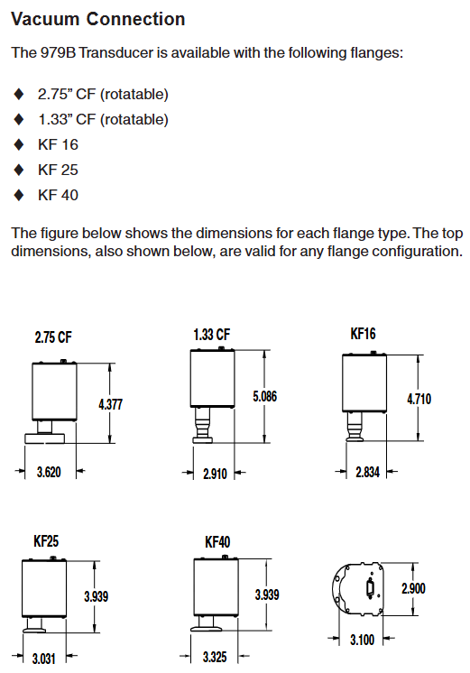
The sensor offers multiple flange types: 2.75 "CF (rotatable), 1.33" CF (rotatable) KF16、KF25、KF40, Corresponding flanges need to be matched according to the system, and the manual provides dimension drawings of each flange for reference.
3. Electrical connection
Cable requirements: Use a 15 pin high-density D-sub female cable with strain relief; To meet the anti-interference requirements of EN61326-1, braided shielded cables are required, with metal hooks connected at both ends of the shielding layer and the power supply grounded.
Pin function: The 15 pin D-sub connector has clear pin division, and the core pins include: 1 pin (RS485-/RS232 TXD), 2 pins (RS485+/RS232 RXD), 3 pins (power+24V), 4 pins (power -), 5 pins (analog output+), 6 pins (analog output -), 9 pins (degassing state), 10 pins (filament selection), 13 pins (degassing on), as well as the common terminals (7, 11, 14 pins) and normal terminals (8, 12, 15 pins) of 3 relays. For details, please refer to the "979B Sensor Electrical Connection Table".
Attention: The negative terminal (6-pin) of the analog output should not be connected to the negative terminal (4-pin) of the power supply or other grounding points (which may cause current diversion and measurement errors, and the longer the cable, the greater the error); When connecting inductive loads (such as solenoids and transformers), an arc extinguishing network (resistor R and capacitor C) needs to be installed. The calculation formula is
C=I 2/(1 × 10 7) (Farads), R=E/I a (ohms, where a=1+(50/E)), and R is at least 0.5 Ω and C is at least 1.0 × 10 ⁻⁹ F.
Operation control
1. Control and status pin operation
Degassing on (Pin13): Enable degassing when grounded, with priority higher than DG command or degassing button; After 30 minutes of degassing, it is necessary to disconnect and reconnect to restart degassing, and degassing should not exceed 30 minutes every 4 hours.
Degassing state (Pin9): When degassing is closed, it is open circuit/suspended, and when it is open, it is grounded; An external pull-up resistor with ≤ 24 VDC can be connected, and the current should be less than 15mA.
Filament selection (Pin10): By switching the active filament on/off the power supply, the state can be switched instead of selecting a fixed filament.
2. Factory default settings
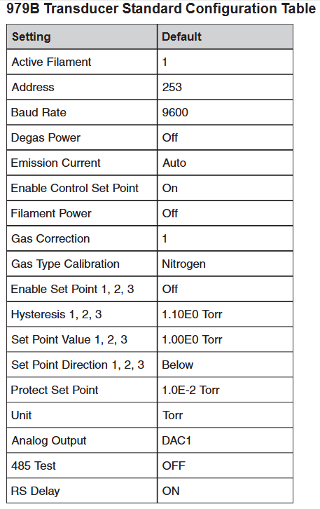
The sensor parameters are preset to default values, including: active filament 1, address 253, baud rate 9600, degassing power off, automatic emission current (20 μ A>1 × 10 ⁻⁴ Torr, 1mA<1 × 10 ⁻⁴ Torr), control set point enabled, filament power off, gas correction 1, gas calibration type nitrogen, 3 set points disabled, hysteresis value 1.10E0 Torr, set point value 1.00E0 Torr, set point direction "below (BELOW)", protection set point 1.0E-2 Torr, unit Torr, analog output DAC1, RS485 test off, RS delay on.
3. RS-485/RS-232 communication protocol
Basic parameters: Supports baud rates of 4800-112200 (default 9600), data format of 8-bit data bits, no checksum, and 1-bit stop bit; RS-485 is a half duplex two-wire system, which is the same protocol as RS-232.
Address rule: Standard address 001-253 (default 253); Universal address 254 (used for communication with unknown address devices, will respond), 255 (broadcast address, executes commands but does not respond, such as batch modification of baud rate).
Command syntax: The query format is @<device address><query command>?; FF (such as querying baud rate: @ 253BR?)?; FF), The command format is @<device address><command instruction>! <Parameters>; FF (such as changing the baud rate to 19200: @ 253BR! 19200; FF); The response starts with ACK (success) or NAK (failure), and the NAK code corresponds to different errors (such as 160=unrecognized message, 169=invalid parameter, 172=value out of range, etc.).
4. Core Command Set
The commands are divided into five categories: setting, status, pressure measurement and degassing, set point, and calibration. The core commands are as follows:
Command Type Command Identification Function Description Example
Set command AF (active filament) to query/select 2 filaments (value 1/2) of the hot cathode sensor. Query: @ 001AF?; FF; Setting: @ 001AF! 2; FF
AD (Address) Query/Set Device Address (001-253) Query: @ 254AD?; FF; Setting: @ 001AD! 002; FF
BR (baud rate) query/set baud rate (4800/9600, etc.) query: @ 001BR?; FF; Setting: @ 001BR! 19200; FF
DAC (Analog Output) Query/Set Analog Output Type (1=DAC1, 2=DAC2) Query: @ 001DAC?; FF; Setting: @ 001DAC! 2;FF
FD (factory default) restores all user calibration values to factory default command: @ 001FD!; FF
Status command DT (device type) query device type response: @ 001ACKMP-HC 979B; FF
FS (filament status) query for the on/off status of the active filament: @ 001FS?; FF
FV (firmware version) query firmware version response: @ 001ACK1.00; FF
SN (serial number) query device serial number response: @ 001ACK0000012345; FF
T (sensor status) query hot cathode status (F=filament fault, G=hot cathode on, etc.) Response: @ 001ACKO; FF (O=normal)
Pressure measurement and degassing FP (filament power supply) switch filament power supply (only effective when the control setpoint is disabled, disabled when the pressure is greater than 5 × 10 ⁻ Torr) command: @ 001FP! ON; FF
DG (degassing power supply) switch degassing (pressure must be<1 × 10 ⁻⁵ Torr, automatically shuts off after 30 minutes) query: @ 001DG?; FF; Setting: @ 001DG! ON; FF
PR1/PR2/PR3 (pressure readings) respectively read MicroPirani (PR1, above 1 × 10 ⁻³ Torr), hot cathode (PR2, below 1 × 10 ⁻⁴ Torr), and combined reading (PR3, full range). Query: @ 001PR1?; FF; Response: @ 001ACK1.23E-2; FF
The set point command SPx (set point value) queries/sets the pressure values (Scientific notation) of the three set points: @ 001SP1! 1.00E-3; FF
SDx (Setpoint Direction) Query/Set Setpoint Direction (BELOW/ABOVE) Setting: @ 001SD1! ABOVE; FF
SHx (hysteresis value) query/set the set point hysteresis value (to avoid relay jitter and match direction) setting: @ 001SH1! 1.10E-3; FF
ENx (Enable Setpoint) Enable/Disable 3 Setpoint Commands: @ 001EN1! ON;FF
Calibration command ATM (atmospheric pressure calibration) to calibrate MicroPirani to full range (requires ventilation to atmospheric pressure, stable for 20 minutes) Command: @ 001ATM! 7.60E+2; FF
VAC (vacuum calibration) calibration MicroPirani zero point (needs to be drawn to<1 × 10 ⁻⁴ Torr, stabilized for 20 minutes, automatically calibrated when hot cathode pressure<1 × 10 ⁻⁴ Torr) command: @ 001VAC!; FF
GT (gas type) query/setting MicroPirani's measurement gas (nitrogen/air/argon, default nitrogen) setting: @ 001GT! ZEROGEN; FF
GC (gas correction) query/set gas correction coefficient for hot cathode (0.10-50.1, default 1, such as argon 1.29) setting: @ 001GC! 1.29; FF
Analog output and gas correction
1. Simulation output calculation and table
DAC1: Pressure calculation formula P=10 (2V − 11) (Torr), the manual provides a detailed voltage correspondence table for 1.0E-10 Torr (0.50V) to 1.0E+03 Torr (7.00V).
DAC2: Pressure calculation formula P=10 0.75 V − 7.75 (Torr), also provide a complete pressure voltage correspondence table.
2. Gas correction factor
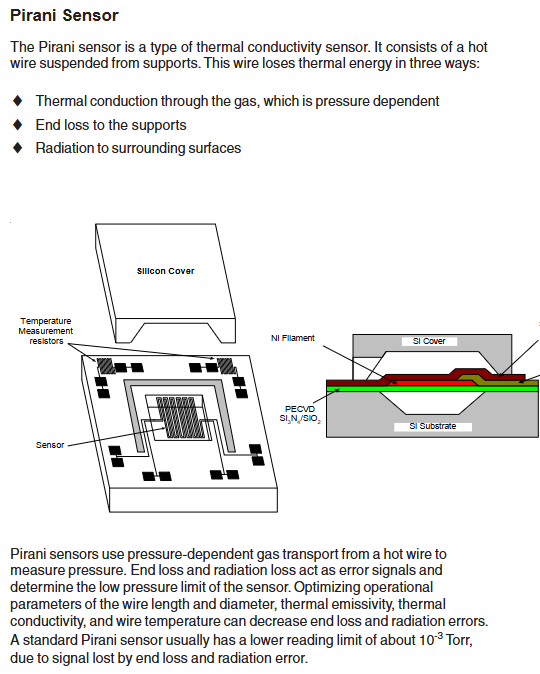
MicroPirani is based on gas thermal conductivity measurement, and the hot cathode is based on gas ionization measurement, both of which need to be corrected according to the gas type:
Gas chemical formula gas correction factor (GC)
Air -1.00
Argon gas Ar 1.29
Carbon dioxide CO ₂ 1.24
Deuterium gas D ₂ 0.35
Helium He 0.18
Hydrogen H ₂ 0.46
Krypton gas Kr 1.94
Neon gas Ne 0.30
Nitrogen N ₂ 1.00
Nitric oxide NO 1.16
Oxygen O ₂ 1.01
Sulfur hexafluoride SF ₆ 2.50
Water H ₂ O 1.12
Xenon Xe 2.87
Maintenance and troubleshooting
1. Daily maintenance
Cleaning: The casing can be cleaned with water or alcohol to prevent liquids from entering the electronic casing; The sensor tube must not be cleaned (as it may damage the components), and the sensor needs to be replaced in case of severe contamination.
Degassing operation: When the hot cathode sensor is contaminated by process gas (especially when the sensitivity drifts when the pressure is ≤ 10 ⁻⁸ Torr), regular degassing is required; When degassing, the pressure should be less than 1 × 10 ⁻⁵ Torr. During this period, the pressure can be measured but the reading may be higher than the system pressure. When the pressure is greater than 1 × 10 ⁻⁴ Torr, degassing is paused and restarted after reaching the threshold. It will automatically terminate after 30 minutes, and degassing should not exceed 30 minutes every 4 hours.
2. Common faults and solutions
Possible causes/solutions for the fault phenomenon
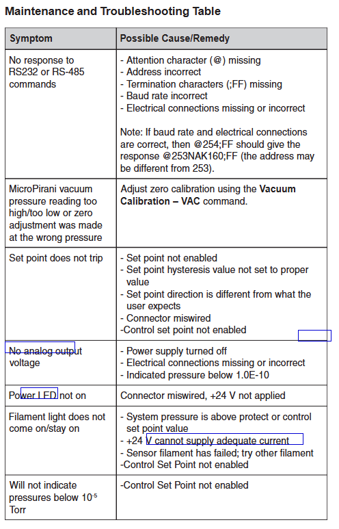
RS-485/RS-232 no response 1. Missing starting character @; 2. Address error (you can try @ 254; FF query); 3. Missing termination character; FF; 4. Baud rate mismatch; 5. Missing/incorrect electrical connections
MicroPirani reading too high/too low/
- YOKOGAWA
- Reliance
- ADVANCED
- SEW
- ProSoft
- WATLOW
- Kongsberg
- FANUC
- VSD
- DCS
- PLC
- man-machine
- Covid-19
- Energy and Gender
- Energy Access
- Renewable Integration
- Energy Subsidies
- Energy and Water
- Net zero emission
- Energy Security
- Critical Minerals
- A-B
- petroleum
- Mine scale
- Sewage treatment
- cement
- architecture
- Industrial information
- New energy
- Automobile market
- electricity
- Construction site
- HIMA
- ABB
- Rockwell
- Schneider Modicon
- Siemens
- xYCOM
- Yaskawa
- Woodward
- BOSCH Rexroth
- MOOG
- General Electric
- American NI
- Rolls-Royce
- CTI
- Honeywell
- EMERSON
- MAN
- GE
- TRICONEX
- Control Wave
- ALSTOM
- AMAT
- STUDER
- KONGSBERG
- MOTOROLA
- DANAHER MOTION
- Bentley
- Galil
- EATON
- MOLEX
- Triconex
- DEIF
- B&W
- ZYGO
- Aerotech
- DANFOSS
- KOLLMORGEN
- Beijer
- Endress+Hauser
- schneider
- Foxboro
- KB
- REXROTH
- YAMAHA
- Johnson
- Westinghouse
- WAGO
- TOSHIBA
- TEKTRONIX
- BENDER
- BMCM
- SMC
- HITACHI
- HIRSCHMANN
- XP POWER
- Baldor
- Meggitt
- SHINKAWA
- Other Brands
- UniOP
- KUKA
- IBA
- Beckhoff
-
ADLINK PCI-7433 - switch value acquisition card Isolated Digital Input Card
-
ADLINK PCI-9112 - 51-12252-0D20 Multi-Function Data Acquisition Card
-
ADLINK NUPRO-A301 REV:1.4 - industrial control motherboard PICMG Full-Size SBC
-
ADLINK 51-18502-0A10 - Frame Grabber Image Acquisition Interface Card
-
ADLINK PCI-7296 - 51-12009-0A50 PCB-I-E-925=6DX1 96-CH Parallel Digital I/O Board
-
ADLINK PCI-8132 GP A2 - Motion Control Card 2-Axis Servo & Stepper Controller
-
ADLINK PCI-7442 - switch quantity card data acquisition card 64-CH Isolated Card
-
ADLINK HPX-13S4 - baseboard PICMG 1.3 Passive Backplane Chassis Baseplate
-
ADLINK NuPRO-590 / NTC-567-ZM-F36 - Single Board Computer PCB-I-E-1853=9L21 Half-Size SBC
-
ADLINK PCIe-8332 - 16-axis plate Motion Control Hardware Card
-
ADLINK NuPRO-775 REV.B1 - motherboard Pentium 4 Full-Size PICMG SBC
-
ADLINK PXI-3920 - Embedded Controller 3U PXI cPCI System Intelligence Board
-
ADLINK PCI-8134 - driver card motion control card 4-Axis Controller Board
-
ADLINK HSL-DI32-M-N-011 / HSL-TB32-M-DIN - Digital Input & Base Module PLC Distributed I/O System
-
ADLINK PCI-6216V-206 / PCI-208V 009 - 16 CH 16bit analog output card
-
ADLINK NuPro-E330 - 51-41805-0A20 PCB Single Board Computer Host Board
-
ADLINK PCI-1622C - Card 8-Port RS-232/422/485 PCI Serial Communication Board
-
ADLINK PCIe-7432 - 51-18402-0A10 Carte PCIe Avec Plage D'Entrée Élevée Isolated DIO Card
-
ADLINK PCI-7250 - PCI Acquisition Card 8-CH Relay Output Isolated DI Card
-
ADLINK PCI-7230 - 32-CH Isolated Digital I/O Card
-
ADLINK PCI-8164 - PCB 4-Axis Motion Controller Card
-
ADLINK PCI-7854 - Collection card High-Speed Link Distributed Motion Controller
-
ADLINK NuPRO-935A/LV - industrial control computer motherboard Full-Size PICMG SBC
-
ADLINK IMB-M40H - motherboard IH61-AA4 1155 LGA1155 Micro-ATX Mainboard
-
ADLINK PCI-7248 - Linhua 51-12006-0A40 48-CH Parallel Digital I/O Card
-
ADLINK HPCI-14S12U - Linhua industrial computer baseboard Passive Backplane
-
ADLINK PCI-8132 Rev.A2 - 2-Axis Servo & Stepper Motion Controller Card
-
ADLINK ACL-8111 - ISA card Multi-Function DAQ Card
-
ADLINK ACL-8111 - ISA card Multi-Function Data Acquisition Board
-
ADLINK PCI-7200 REV.A3 - Digital I/O card 12MB/s High-Speed Parallel Digital I/O
-
ADLINK PCI-7296 REV.A3 - 96-CH High-Density Opto-Isolated DIO Card
-
ADLINK PCI-7434 - 64-CH Isolated Digital Output Card
-
ADLINK M-342 - atx motherboard Industrial PC Mainboard
-
ADLINK NuPRO-935ADV (A) 1.9 - CPU Board Intel Core 2 Quad CPU Q9500 2.83GHz PICMG Board
-
ADLINK NUPRO-935A/DV - motherboard dual network port 51-41802-0A10 CPU Board
-
ADLINK PCI-RTV24 - image capture card Analog Video Frame Grabber Board
-
ADLINK HPX-13S4 - device baseboard PICMG 1.3 Passive Backplane Chassis Baseplate
-
ADLINK PCI-8134A - control card 4-Axis Motion Controller Card
-
ADLINK ACL-7130 REV. B2 - industrial control capture card Isolated Digital I/O Board
-
ADLINK EBP-13E2 - Industrial Backplane Board Passive Backplane Baseboard
-
ADLINK NuPRO-935ADV (A) 1.9 - CPU Board Intel Core 2 Quad CPU Q9500 2.83GHz PICMG SBC
-
ADLINK PCI-8134A - motion control card 4-Axis Pulse-Train Controller Card
-
ADLINK PCI-9112 REV A.1 - Multi Function DA&C Board Data Acquisition Card
-
ADLINK 51-12001-0C20 - Circuit Board Multi-Function Data Acquisition Hardware
-
ADLINK PCI-7300A - 80-CH High-Speed Digital I/O Card
-
ADLINK PCI-7230 - 16-CH Isolated Digital Input Output Card
-
ADLINK DIN-814-GP - motion control module Interface Terminal Block
-
ADLINK NUPRO-A40H - 51-41807-1A20 Industrial Control Motherboard LGA1155
-
ADLINK PCI-7433 rev A2 - Isolated Digital Input Card
-
ADLINK NuPRO-780 - Pentium III 800 512 MB SBC NuPRO780 51-41309-0B2 Single Board Computer
-
ADLINK PCI-7853 / PCI-7854 - Acquisition card High-Speed Link Control Card
-
ADLINK NUPRO-852 / NUPRO-852LV - Industrial motherboard Full-Size PICMG CPU Board
-
ADLINK NuPRO-842LV/P - 51-41360-0B30 Industrial Motherboard Half-Size PICMG SBC
-
ADLINK PCI-FIW64 - 4/2 Channel IEEE1394B Image Capture Card Frame Grabber
-
ADLINK PCI-7851 Rev A1.1 - HSL system card High-Speed Link Master Controller
-
ADLINK PCI-7230 - 51-12003-0A50 card 32-CH Isolated Digital I/O Card
-
ADLINK NuPRO-841REV:1.0 - Industrial CPU Board Mainboard
-
ADLINK NuPRO-841 REV:1.0 - motherboard Industrial Control PC Mainboard
-
ADLINK PCI-8256 - 8-Axis Advanced Motion Control PCI Board
-
ADLINK PCI-6S / PCI6S - Backplane 6-Slot Passive Backplane Board
-
ADLINK PCI-7234 REV B3 - 32-CH Isolated Digital Output PCI Card
-
ADLINK PCI-8213 - HannStar MV-4 51-45003-0b4 Board
-
ADLINK PCI-7233 - 51-12004-0a20 board PCI7233 32-CH Isolated Digital Input Card
-
ADLINK PCI-7851 - 006 51-24003-0B20 High-Speed Link Master Motion Control Card
-
ADLINK PCI-7432 - 64-CH Isolated Digital I/O PCI Cards
-
ADLINK LPCI-3488 - Card Low Profile IEEE-488 GPIB Interface Card
-
ADLINK HPCI14S REV.B1 - industrial control computer base plate Passive Backplane
-
ADLINK NEON-1020 - Industrial camera Smart Camera Vision System
-
ADLINK PCI-7432 - Isolated Digital I/O PCI Card 64-CH
-
ADLINK Pcm-7250+ - 8-Ch Relay Outputs & 8-Ch Isolated DI Module PC/104
-
ADLINK CPCI-7841 - DUAL-PORT ISOLATED CAN INTERFACE CARD CompactPCI
-
ADLINK PCI-3488 / PCI-GPIB - PCI IEEE-488 GPIB Interface Card
-
ADLINK PCI-1711U - Card Multi-Function Data Acquisition Board
-
ADLINK NUPRO-A301 - REV:1.1 1.2 1.4 PICMG Full-Size Single Board Computer
-
Adlink DIN-50S-01 - PLOTECH 51-14024-0A40 50-pin Wiring Terminal Board
-
Chroma 52962 / 58183 - PXI Optical Spectrometer carrier adapter Card
-
ADLINK PCI-6208V - PCI DATA ACQUISITION & RECORDING CARD 8-CH Analog Output
-
ADLINK HSL-DI32-DB-N - Industrial Control Board Distributed Digital Input Module
-
ADLINK HSL-AO4-U - 4-CH HIGH SPEED LINK ANALOG OUTPUT MODULE Distributed I/O
-
ADLINK PCI-7396 - 0050 GP 51-12012-0B20 96-CH High-Speed Digital I/O Card
-
ADLINK NUPRO-935A/DV - 51-41802-0A10 motherboard Industrial CPU Single Board Computer
-
ADLINK PCI-9111 DG - Industrial Acquisition Card Multi-Function DAQ Card
-
ADLINK NuPRO-E315 - industrial computer motherboard Intel Atom SHB SBC
-
ADLINK NUPRO-406 REV:B1 - Industrial Control Motherboard Full-Size PICMG CPU Board
-
ADLINK NuPRO-E330 - motherboard Industrial Control System Host Board PICMG 1.3
-
ADLINK ACL-6128A 103 - 51-11002-1A4 2-CH Isolated Analog Output Card
-
XTRAMUS cPS-H325/AC - POWER SUPPLY NUSTREAMS 600 NETWORK TESTING EQUIPMENT Power Module
-
ADLINK DIN-814P-A4 - 51-14056-0A10 Terminal Block Motion Control Breakout Board
-
ADLINK TB-24P/24-01 - 24-Channel Card Terminal Breakout Board
-
ADLINK PCI-7251 - 51-12008-0A30 PCI7251 8-CH Relay Output Isolated Digital Input Card
-
ADLINK HSL-TB64-DIN REV A1 / HSL-DO32-DB-N - 2ea Board Breakout Terminal Board Distributed I/O Module
-
ADLINK NuPRO-865 REV 3.0 - industrial computer motherboard Full-Size PICMG SBC
-
ADLINK NUPRO-A40H - motherboard 51-41807-1A30 OSP H61 Industrial PC Mainboard
-
ADLINK LPCI-3488A - PCI Card 51-12801-0A30 GPIB Interface Card
-
ADLINK DIN-825-4P0 - 51-14085-0A30 Terminal Printed Circuit Board Breakout Block
-
ADLINK IMB-T10/D2550 V - MOTHER BOARD 80-PXG160-A1A01 IMB-T10-M2G-S32G Industrial Mainboard
-
ADLINK PCI-8144N - Motion Control card Stepper Motor Controller
-
ADLINK PCI-7433 - Digital acquisition card Isolated Digital Input Card
-
ADLINK PCI-9112 DG - Data Acquisition card 51-12252-0D20 Multi-Function DAQ
-
ADLINK IMB-M40H - motherboard IH61-AA4 1155 LGA1155 Micro-ATX Mainboard
-
ADLINK TB-24P/24-01 - Carte 24 voies Terminal Breakout Board Connector Module
-
ADLINK HSL-D16DO16-M-NN - Distributed Discrete Input Output I/O Module
-
ADLINK PCI-7248 - PCI CARD 51-12006-0A40 48-CH Parallel Digital I/O Board
-
ADLINK HSL-DI32-DB-N - Industrial Control Board Distributed I/O Digital Input Module
-
ADLINK PCI-7433 - Pci 7433 Isolated Digital Input Card
-
ADLINK PCI-6208V - 008 Data acquisition card 8-CH Analog Output Card
-
ADLINK IH61-AA4 - industrial motherboard LGA1155 Micro-ATX Mainboard
-
ADLINK PXI-3920 - PXI 3U cPCI Industrial Controller Embedded System CPU Board
-
ADLINK PCI-6308 - Analog Output DAQ Card Isolated Voltage Output Card
-
ADLINK PCI-7200 - data acquisition card REV.A3 High-Speed Parallel DIO Card
-
ADLINK NuPRO-E315 - Industrial Control Computer Motherboard PICMG 1.3 SHB SBC
-
ADLINK PCI-1610C - Card 4-Port Isolated RS-232 PCI Serial Communication Card
-
ADLINK PCI-1716 - Card High-Resolution Multi-Function DAQ Card
-
ADLINK MI-965 - Industrial Mini-ITX Motherboard CPU Board
-
ADLINK PCI-1610A - Card 4-Port RS-232 PCI Serial Communication Card
-
ADLINK cBP-3208/3208R - CPCI Board 3U 8-Slot CompactPCI Backplane
-
ADLINK PCI-8134A - 51-12421-0A10 4-Axis Motion Controller Card
-
ADLINK PCI-8164 - Motion Control Card 4-Axis Advanced Controller Card
-
ADLINK NUPRO-935A/DV - motherboard dual network port 51-41802-0A10 CPU Board
-
ADLINK PCI-7248 - 51-12006-0A40 acquisition card 48-CH Parallel DIO Card
-
ADLINK PCI-7443 - 51-12022-0A10 BOARD 128-CH Isolated Digital Input Card
-
ADLINK DIN-825-GP4 - Terminal Block Interface Board Breakout Module
-
ADLINK PCI-7248 - Card 48-CH Parallel Digital I/O Card
-
ADLINK NUPRO-865 REV :3.0 - industrial motherboard Intel Pentium 4 CPU Board
-
ADLINK PCI-9113A - Isolated Analog Input Data Acquisition Card
-
ADLINK HPCI-8S4 - REV.B2 Industrial Control Base Plate Passive Backplane
-
ADLINK M-342 - atx motherboard Industrial PC Mainboard
-
ADLINK PCI-RTV24 - image capture card Analog Video Frame Grabber Board

K-JIANG

Add: Jimei North Road, Jimei District, Xiamen, Fujian, China
Tell:+86-15305925923