
K-WANG


ABB MNS iS Motor Control Center System
ABB MNS iS Motor Control Center System
Product positioning: MNS iS is an intelligent motor control center upgraded based on MNS series technology, integrating protection, control, and monitoring functions, suitable for industrial production lines, energy facilities, and other scenarios. Through modular design, it achieves efficient operation and maintenance as well as full lifecycle cost optimization.
Core characteristics and values of the system
1. Core advantages
High safety: The power and control areas are physically isolated, complying with the IEC 61439 series standards, supporting arc fault protection (up to 100 kA/300 ms), ensuring the safety of personnel and equipment.
Standardization and flexibility: The fully pre installed power module (MStart) supports multiple starter types (direct start, star delta start, etc.), and the control module (MControl) can expand its functionality through software configuration without the need for additional hardware.
Low lifecycle cost: Reduce downtime through predictive maintenance (condition monitoring), standardize modules to lower inventory requirements, and simplify troubleshooting processes.
Intelligent information management: integrates web servers with industrial communication protocols (Profibus, Profinet, etc.), supports remote monitoring and data analysis, and achieves digital operation and maintenance.
2. Innovative design
Functional module separation: The power module (MStart) and control module (MControl) operate independently, supporting live module replacement and improving system availability.
Transformer free sensing technology: high-precision shunt sensors are used to measure current, voltage, and temperature, replacing traditional transformers and reducing energy consumption and space occupation.
Plug and play architecture: modules automatically identify location and type, communication networks automatically configure, reducing engineering complexity.
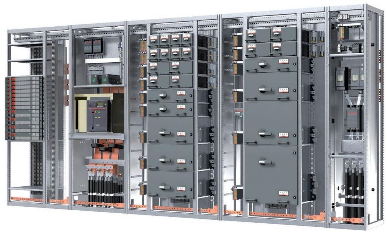
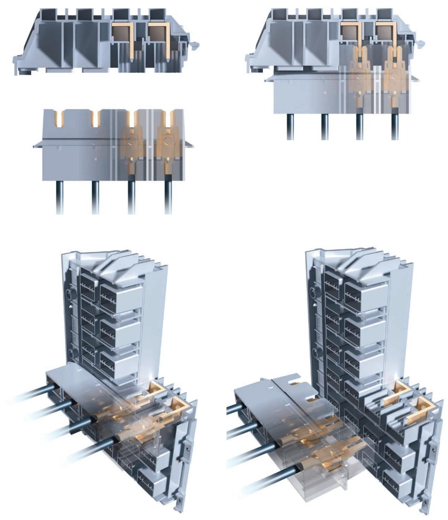
System Architecture and Components
1. Hardware composition
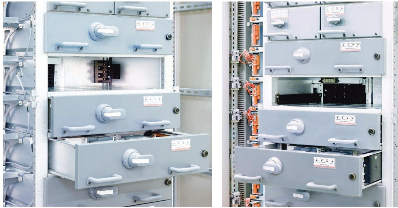
Power module (MStart):
Includes isolators, short-circuit protection devices (fuses or circuit breakers), contactors, and sensor modules.
Supports drawer style (6E/4 to 24E sizes) and fixed style (suitable for motors ≥ 250 kW) installation, compatible with voltage levels of 400 V, 500 V, and 690 V.
Control module (MControl):
The core controller is responsible for protecting algorithms (overload, phase loss, ground fault, etc.), logic control, and data acquisition.
Support the expansion of I/O interfaces (digital, analog, PTC/PT100 temperature input) to meet different on-site signal requirements.
Communication and Interface Module:
MLink: As a gateway connecting upper level systems, it supports protocols such as Profibus DP, Profinet, Modbus, and has a built-in web server.
MView: Local Human Machine Interface (HMI), supports touch operation and status monitoring, and can be accessed remotely through the network.
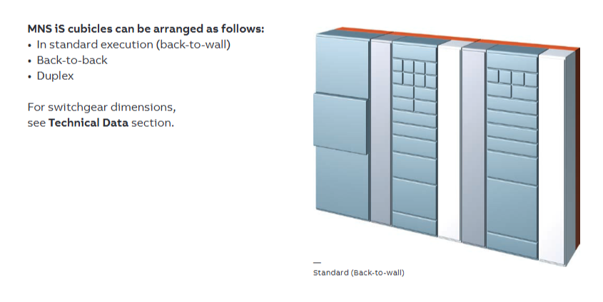
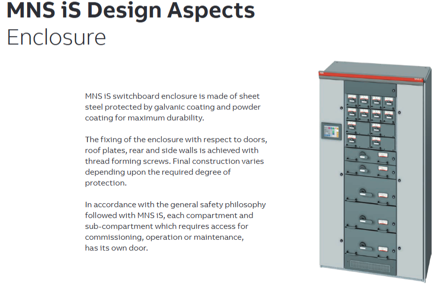
2. Structural design
Partition separation: Vertical and horizontal partitions strictly distinguish equipment areas, control cable areas, power cable areas, and busbar areas to avoid electromagnetic interference, and support different key lock control access permissions.
Busbar system: The main busbar is located at the rear of the cabinet and adopts a maintenance free design (copper material, optional silver plating or insulation sleeve). It is safely isolated from the equipment area through a multifunctional isolation wall (MFW).
Cable management: Power and control cable partition wiring, supporting up and down incoming lines, suitable for different installation scenarios.
Control and protection functions
1. Protection function module
Thermal Overload Protection (TOL): Based on the IEC 60947-4-1 standard, it calculates the motor's thermal capacity, provides "trip time" and "reset time" warnings, and supports ATEX certification scenarios.
Motor abnormal protection: monitors phase loss, current imbalance, undervoltage, grounding faults, etc., and can be configured with alarm or trip actions.
Process monitoring and protection: including blockage, underload, no-load, and limit of starting times, to prevent mechanical failures (such as pump cavitation).
2. Maintenance and status monitoring
Predictive maintenance: Monitor parameters such as the number of contactor actions, module insertion times, operating hours, and contact temperature, and trigger an alarm when the threshold is exceeded.
System self diagnosis: Automatically verify module type and position matching, communication status, and control voltage to ensure system integrity.
Communication and Integration
Communication architecture and core components
1. Communication nodes and hierarchy
The communication system of MNS iS adopts a distributed architecture and is divided into three levels of nodes:
On site level: With MControl as the core, responsible for the protection, control, and data acquisition of a single motor, communicating with the power module (MStart) through an internal bus.
Network level: Multi node aggregation is achieved through MLink gateway, supporting interaction with upper level systems, and can connect up to 60 MControl modules.
Monitoring level: Integrated MView local human-machine interface and web server, supporting remote access and configuration.
2. Key communication components
Component Function Description
MControl has a built-in communication interface that supports real-time data exchange with MStart modules (current, temperature, status, etc.) and can be directly connected to Profibus DP/Profinet networks.
As a system gateway, MLink supports protocols such as Profibus DP, Profinet, Modbus RTU/TCP, OPC, etc., enabling integration with PLC, SCADA and other systems, while also providing web server functionality.
MView local touch panel (optional), displaying motor status, alarm information, and operation buttons based on a web interface, supporting permission management.
Communication Protocol and Interface
1. Supported protocol types
Industrial bus protocol:
Profibus DP/DP V1 (slave mode, supporting process data and diagnostic information transmission);
Profinet I/O (compatible with ABB systems and supports real-time communication);
Modbus RTU (serial communication) and Modbus TCP (Ethernet communication).
General Agreement:
Built in web server, supporting access to monitoring interface through standard browsers;
OPC interface, easy to integrate with third-party SCADA or MES systems;
NTP (Network Time Protocol) enables system wide time synchronization.
2. Data transmission capability
Internal communication: A 10 Mbps real-time bus is used between MControl and MLink, with a command response time of approximately 2 ms for a single MControl and a total system response time of ≤ 258 ms for 60 nodes.
External interaction:
The maximum transmission rate of Profibus DP is 12 Mbps;
Profinet and Modbus TCP support 100 Mbps Ethernet transmission;
Support data block read and write (such as motor current, temperature, tripping reasons, etc.) and remote control commands (start/stop/reset).
System integration capability
1. Integration with upper level systems
Process Control System (PCS): Using MLink as a gateway, the motor status and measurement values (current, power, energy consumption) are uploaded to PLC or DCS, and control instructions are received to achieve remote operation.
Electrical network monitoring system: supports sending electrical parameters (such as harmonics and power factor) to the energy management system (EMS) to assist in energy optimization.
Maintenance management system: Push equipment health data (contactor action frequency, operating hours, temperature trend) to CMMS (computerized maintenance management system) through OPC interface, supporting the development of predictive maintenance plans.
2. Redundancy and reliability design
Dual redundant communication: supports two independent communication paths (primary/backup MLink). When the primary link fails, it automatically switches to the backup link to ensure uninterrupted operation, with a switching time of ≤ 100 ms.
Communication fault protection: Configure the "fail safe" mode (such as keeping the motor running/stopping in case of communication interruption) to avoid unexpected shutdowns caused by network issues.
Time synchronization and data consistency
Synchronization mechanism: Implement system wide time calibration through NTP protocol, support access to factory level time servers (such as GPS synchronization sources), and ensure that the timestamp accuracy of event records (alarms, trips) is ≤ 1 ms.
Data timeliness: The update cycle of key measurement values (such as current and temperature) can be configured (default 100 ms) to meet real-time monitoring requirements; Historical data (energy consumption, number of actions) is stored at the minute level and supports trend analysis.
- YOKOGAWA
- Reliance
- ADVANCED
- SEW
- ProSoft
- WATLOW
- Kongsberg
- FANUC
- VSD
- DCS
- PLC
- man-machine
- Covid-19
- Energy and Gender
- Energy Access
- Renewable Integration
- Energy Subsidies
- Energy and Water
- Net zero emission
- Energy Security
- Critical Minerals
- A-B
- petroleum
- Mine scale
- Sewage treatment
- cement
- architecture
- Industrial information
- New energy
- Automobile market
- electricity
- Construction site
- HIMA
- ABB
- Rockwell
- Schneider Modicon
- Siemens
- xYCOM
- Yaskawa
- Woodward
- BOSCH Rexroth
- MOOG
- General Electric
- American NI
- Rolls-Royce
- CTI
- Honeywell
- EMERSON
- MAN
- GE
- TRICONEX
- Control Wave
- ALSTOM
- AMAT
- STUDER
- KONGSBERG
- MOTOROLA
- DANAHER MOTION
- Bentley
- Galil
- EATON
- MOLEX
- Triconex
- DEIF
- B&W
- ZYGO
- Aerotech
- DANFOSS
- KOLLMORGEN
- Beijer
- Endress+Hauser
- schneider
- Foxboro
- KB
- REXROTH
- YAMAHA
- Johnson
- Westinghouse
- WAGO
- TOSHIBA
- TEKTRONIX
- BENDER
- BMCM
- SMC
- HITACHI
- HIRSCHMANN
- XP POWER
- Baldor
- Meggitt
- SHINKAWA
- Other Brands
- UniOP
- KUKA
- IBA
- Beckhoff
-
Basler Electric DECS-250-CN1SN1N Automatic Voltage Regulator for Generator Excitation Control
-
ADLINK CPCI-6860A - 51-31310-OB10 industrial motherboard CompactPCI SBC
-
ADLINK AmITX-SL-G-H110 - 51-7A104-0A30 Mini-ITX Industrial Motherboard
-
ADLINK PXI-2005-003 - CPCI Industrial PC Data Acquisition Card Multi-Function DAQ
-
ADLINK DININ-814M - 51-14032-0A3D SCSI-100P cable connection Interface Terminal Board
-
ADLINK CPCI-3920NA/C2D15/M1G - 3U CompactPCI Intel Core 2 Duo Single Board Computer
-
ADLINK PCIE-8560 - 51-18014-0A20 Communication Card High Speed DAQ
-
ADLINK PCI-C154+ - Motion Control Card 4-axis Motion Controller Board
-
ADLINK PCI-RTV24 - image capture card Analog Video Frame Grabber
-
ADLINK NuPRO-842LV/P - 51-41360-0B30 Industrial Motherboard CPU Board
-
ADLINK cBP-3208/3208R - CPCI Board 3U 8-Slot CompactPCI Backplane
-
ADLINK PCI-8164 - 4-Axis Motion Controller PCI Card 51-12406-0A40
-
ADLINK PCIe-GIE64+ - 4-CH GigE Vision PoE+ Frame Grabber Video Capture Card
-
ADLINK CPCI-6860 / 6860A - CompactPCI Dual Xeon Single Board Computer
-
ADLINK IEC-915GV - REV 1.1 Industrial motherboard CPU Board
-
ADLINK ND-6520 - Technology RS-232 to RS-422RS-485 Converter NuDAM Module
-
ADLINK RTV-24 / PCI-MP4S - 51-12519-1C30 4-Channel Real Time Video Capture Board
-
ADLINK cPCI-6910 / cPCI-6910AM/M1G - cPCI-6910AM/DXL16/M1G/S80G(G)-3120 BOARD CompactPCI SBC
-
ADLINK NUPRO-A40H - Linghua 51-41807-1A30 Industrial Control Computer Motherboard
-
ADLINK USB-3488A - USB to GPIB INTERFACE USB-3488A(G) Controller Module
-
ADLINK PCI-8134A - motion control card 4-Axis Controller Card
-
ADLINK PCI-7432 - Board 32-Channel input / 32-output Isolated Digital I/O PCI Card
-
ADLINK PCI-8134A - 51-12421-0A10 motion controller card tested
-
ADLINK LPCIe-7230 - 32 CH Isolated Input/output Card 2 Interrupts Low Profile PCIe
-
ADLINK NuPRO-E340 - industrial computer motherboard 51-47807-0A30 PICMG 1.3 SHB
-
ADLINK PCI-7434 - High-speed Digital Acquisition Card 64-CH Isolated DO Card
-
ADLINK NuPRO-E330 - 51-41805-0A20 Indsutrial Board SHB Single Board Computer
-
ADLINK PCI-7248 - OPTO-22 48 CHANNEL DIO DIGITAL TTL/DTL I/O 51-12006-0A40 GP
-
ADLINK PCI-8134 - Motion control card 4-Axis Controller Card
-
ADLINK AMP-208C - Movimiento Control Tarjeta 51-12420-1A20 W/Expansión & Breakout
-
ADLINK PCI-8164 - 51-12406-0A40 PCB Board 4-Axis Motion Controller Card
-
ADLINK DIN-68Y-SGII / DIN-68M-J3A - Terminal Board Connector Interface Block
-
ADLINK PCIe-7432 - Technology 51-18402-0A10 PCIe Card With High Input Range
-
ADLINK PCI-8144 / PCI-8144N - Motion control card 4-Axis Stepper Controller Card
-
ADLINK HSL-HUB3/REPEATER - HIGH SPEED LINK EXTENSION MODULES Distributed Hub Module
-
ADLINK ND-6017 - Data Logging + Acquisition 8CH A/D input Mod NuDAM Module
-
ADLINK LPCIe-7250 - data acquisition card Low Profile 8-CH Relay Output Card
-
ADLINK PCI-7432 - I/O card 64-CH Isolated Digital Input Output PCI Card
-
ADLINK IMB-M43H - industrial control computer motherboard Q87 Chip Micro-ATX
-
ADLINK MP-C154 - Motion control Card 4-Axis Motion Controller Board
-
ADLINK PCI-RTV24 - image capture card Video Frame Grabber Card
-
ADLINK PCI-7250 - 8-CH Relay Output & 8-CH Isolated DI Card
-
ADLINK PCI-6308V - 8-CH 12-Bit Isolated Analog Output PCI Card PCB-I-E-1148=6EX2
-
ADLINK PCI-7248 - capture card 48-CH Opto-22 Compatible DIO Card
-
ADLINK HSL-AI16A02-M-VV - Analog Input Output Distributed Module
-
ADLINK NuPRO-A301 - Rev:1.4 NUPRO-A301 PICMG Full-Size Single Board Computer
-
ADLINK PCI-6208V-GL - 8-CH Voltage Analog Output PCI Card
-
ADLINK PCI-8134A - 51-12421-0A10 4-Axis Motion Controller Card
-
ADLINK MNET-S23 - TECHNOLOGY MNET S23 - SERVO DRIVER CONTROL MODULE
-
ADLINK M-342 - ATX I3 I5 I7 Q67 Industrial Motherboard
-
ADLINK NUPRO-780 - Industrial Motherboard CPU Board PICMG SBC
-
ADLINK MP-C154 / MP-C152 - 4-Axis Motion Control Card Pulse-Train Controller
-
ADLINK NuPRO-935A/LV10B0 - Motherboard 51-41802-0A10 GP w/RAM Industrial Control Board
-
ADLINK MP-C154 - Motion control card 4-Axis Motion Controller Mainboard
-
ADLINK PCI-7250 - PCI Acquisition Card 8-CH Relay Output Isolated DI Card
-
ADLINK ACL-7124 - Technology Inc.24 DIO Card Digital Input Output Card
-
ADLINK PCI-8554 A2 - Timer/Counter Data Acquisition Card
-
ADLINK DIN-825-GP4 - Terminal Block Interface Board Breakout Module
-
ADLINK NuPR0-761 - REV:1.1 Industrial motherboard Full-Size PICMG SBC
-
ADLINK MXE-1401/M8G (G) - Matrix Fanless Embedded Computer Industrial PC
-
ADLINK HSL-DI16DO16-UD-NN - Digital 16 Channel I/O Mod Distributed I/O Module
-
ADLINK ND6520 - NUDAM INTELLIGENT DA&C MODULE RS232-RS-422/RS485 CONVERTOR
-
ADLINK NUPRO-761 - REV:1.1 Industrial Motherboard CPU Board
-
ADLINK AMP-208C - Motion Control Card 51-12420-1A20 DSP-based 8-axis
-
ADLINK NuPRO-A301REV 1.4 - with packaging industrial computer motherboard PICMG SBC
-
ADLINK PCM-9112+ - 51-12300-0A2 industrial motherboard Multi-Function DAQ PC/104 Module
-
ADLINK PCM-7250+ - 8-CH Relay Outputs & 8-CH Isolated DI Module PC/104
-
ADLINK PCI-RTV24 - Image capture card Analog Video Frame Grabber
-
ADLINK PCI-8134 - Motion Controller PCI Card 4-Axis Controller Board
-
ADLINK PCI-7432 - Isolated Digital I/O PCI Card
-
ADLINK PCI-8554 A2 - acquisition card Timer/Counter Card
-
ADLINK PCI-8132 - Rev.A2 2-Axis Servo & Stepper Motion Controller Card
-
ADLINK PCI-8132 - Data Acquisition card 2-Axis Motion Controller Card
-
ADLINK EBP-13E4 - 51-46703-0A30 Industrial Backplane Board Passive Backplane
-
ADLINK PCI-800L - Electronic Card Interface Controller Card
-
ADLINK PCIe-GIE72 - 51-18531-0A10 PCB Board GigE Vision Frame Grabber
-
ADLINK DAQ-2010(G)-OOBO - Simultaneous-Sampling Multi-Function DAQ Card
-
ADLINK PCI-9112 - REV.B1 Multifunction DAQ Card Data Acquisition Card
-
ADLINK PCI-7230 - 51-12003-DA60 32-CH Isolated Digital I/O Card
-
ADLINK PCI-7432 - Data Acquisition Card Isolated Digital I/O PCI Card
-
ADLINK ETX-AT-N270-18/LXE - 51-71111-0A20 ETX CPU Module Motherboard
-
ADLINK HSL-DI32-UD-N - DIGITAL INPUT 32 POINTS MODULE Distributed I/O
-
ADLINK AMP-204C - Motion Control card DSP-Based 4-Axis Advanced Controller
-
ADLINK MNET-4XMOG-0050 - Four-axis Motion Controller Distributed Motion Module
-
ADLINK AMP-204C - Motion control card DSP-Based 4-Axis Pulse-Train Controller
-
ADLINK PCI-7442 - Switch card 64-Channel Datalogging & Acquisition Card
-
ADLINK M-302 - Industrial control motherboard ATX PC Board
-
ADLINK NUPRO-852 / NUPRO-852LV - Industrial motherboard Single Board Computer
-
ADLINK PCI-8134 - REV.B1. 4-Axis Motion Controller Card
-
ADLINK PCI-GIE62 + - 51-18502-0A20 2-CH GigE Vision Frame Grabber PoE Card
-
ADLINK PCI-MPG24 - 51-12523-0B20 MPEG4 Card Video Compression Hardware
-
ADLINK HSL-TB32-M-DIN - 32-CH I/O TERMINAL W/ HSL-AI16AO2-M-VV MODULE
-
ADLINK PCI-M114-GL - PCB Ver 2.1 Motion Controller Axis Card
-
ADLINK IMB-M40H - SYM76996H61 motherboard Industrial Computer Mainboard
-
ADLINK NUPRO-A40H - 51-41807-1A20 industrial control motherboard H61 Chip
-
ADLINK PCI-M114-GL - Axis Card Data Acquisition Card PCB VER2.2 Motion Controller
-
ADLINK PCI-8134 - Motion Controller PCI Card 4-Axis Controller Board
-
ADLINK PCI-8102 - Motion control card 2-Axis Servo & Stepper Controller
-
ADLINK NuPRO-841REV:3.0 - motherboard Industrial Control PC Board
-
ADLINK HSL-TB32-U-DIN REV A1 - Breakout Terminal Board Field I/O Module
-
ADLINK AMP-204C - Motion Control card DSP-Based 4-Axis Pulse-Train Controller
-
ADLINK NUPRO-A40H - 51-41807-1A20 industrial control motherboard H61 PC Board
-
ADLINK PCI-6308A / PCI-6308V - 51-12202-0A50 Isolated Analog Output Card
-
ADLINK AMP-204C - DSP-Based 4-Axis Advanced Pulse-Train Motion Controller
-
ADLINK PCI-7434 - Technology 64-Channel Isolated Digital I/O PCI Cards
-
ADLINK CPCI-6840 / CPCI-6840V / PM16/M1G-12G0 - CompactPCI Single Board Computer CPU Module
-
ADLINK PCIE-GIE74 - Motherboard Video Capture Card 51-18531-0A10 Frame Grabber
-
ADLINK NuPRO-E330 - industrial computer equipment motherboard Control Mainboard
-
ADLINK AMP-208C / 51-12420-1A20 - Motion Control Card W/ Expansion & Breakout Board
-
ADLINK HPCI-14S12U - industrial computer baseboard Passive Backplane 14 Slots
-
ADLINK PCI-8164 - 4-Axis Motion Controller PCI Card W/ 1x Cable, 1x Breakout Box
-
ADLINK PCIe-RTV24 - 51-18016-0A20 Image Acquisition Video Capture Card
-
ADLINK M-342 - 5 PCI ATX Motherboard Industrial PC Mainboard
-
ADLINK PCI-FIW64 - 4/2 Channel IEEE1394B Image Capture Card FireWire Frame Grabber
-
ADLINK PCI-7432 - digital IO card 64-CH Isolated Digital Input Output Card
-
ADLINK 51-12001-0C20 - Circuit Board PCI-7200 Data Acquisition Controller Card
-
ADLINK PXI-3920 - PXI 3U cPCI Industrial Controller Embedded System CPU Board
-
ADLINK NuPRO-841REV:2.0 - motherboard Industrial Control PC Board
-
ADLINK NuPro-E330 - 51-41805-0A20 PCB Industrial Control Computer Motherboard
-
ADLINK PCI-RTV24 - Image capture card Analog Video Frame Grabber
-
ADLINK PCI-7442 - Switch card 64-Channel Datalogging & Acquisition Card
-
ADLINK HPX-13S4 - device baseboard Passive Backplane Riser Card
-
ADLINK PCI-9112 REV A.1 - Multi Function DA&C Board Data Acquisition Card
-
ADLINK PCI-7248 - 51-12006-0A40 Card Control 48-CH Digital I/O Module
-
ADLINK CPCI-6860 / 6860A - motherboard CompactPCI Dual Xeon Single Board Computer
-
ADLINK DPAC-3020-11(G) - Embedded PC Automation Controller Machine Control Board
-
ADLINK NuPRO-841 REV:1.0 - industrial control motherboard CPU Board
-
ADLINK MNET-4XMOG-0050 - Four-axis Motion Controller MNET Motion Control Card

K-JIANG

Add: Jimei North Road, Jimei District, Xiamen, Fujian, China
Tell:+86-15305925923