
K-WANG
+086-15305925923
Service expert in industrial control field!


Product
Article
NameDescriptionContent
Adequate Inventory, Timely Service
pursuit of excellence


Ship control system
Equipment control system
Power monitoring system
Current position:
新闻动态
newS
Brand
GE MVME5500 VMEbus Single Board Computer
GE MVME5500 VMEbus Single Board Computer
GE MVME5500 VMEbus Single Board Computer
WARNING – Bodily injury. These symbols, and the signal word "WARNING", indicate a
potentially dangerous situation. Failure to observe this safety information could result in death
or severe injury. The text may state the hazard, how to avoid the hazard, and the result if not
followed. The bolt is for electrical warnings; the exclamation point is for general warnings.
WARNING, HOT SURFACE – Bodily injury. This symbol indicates a potentially hot
surface. Avoid contact with a hot surface.
NOTICE – Equipment damage or loss of data or cybersecurity risk. This symbol
indicates a potential for equipment damage, loss of data or another unintended outcome.
Failure to observe this information may result in damage to or destruction of the product
and / or other system components.
IMPORTANT NOTE: This symbol indicates operator tips, particularly useful information, or
important information about the product or its further uses.
Potential safety hazards
Before beginning installation, repair, or maintenance on the analyzer, read the safety information
below and contact the local Safety Department to ensure that all safety guidelines, regulations, and
procedures are followed. This includes obtaining the proper work permits.
The user is responsible for being familiar and complying with all safety and health guidelines,
regulations, and procedures at the analyzer location. Consult Material Safety Data Sheets for safety
requirements.
Become familiar with the application specifications before working on the analyzer.
DANGER – Serious damage to health / risk to life. When working on the analyzer,
there is the possibility of exposure to hydrogen, nitrogen, and other compressed gases. All
appropriate precautions and extreme care should be taken when working with compressed
gases.
DANGER – Serious damage to health / risk to life. Before opening analyzer enclosure
doors, be sure the area is safe from hazardous gases and will remain so the entire time the
analyzer is open.
Ensure there is no hazardous atmosphere present when performing maintenance on the
unit. Do not separate components when energized. This applies to all connectors and
connections, cabling and wiring.
WARNING – Bodily injury. Wear protective clothing and equipment, such as rubber gloves
and goggles or safety glasses with side shields.
WARNING – Bodily injury. Apply power only after the procedures are complete. Technicians
must perform the procedures in order: plan, install, wire, verify the power-on sequence, and
configure.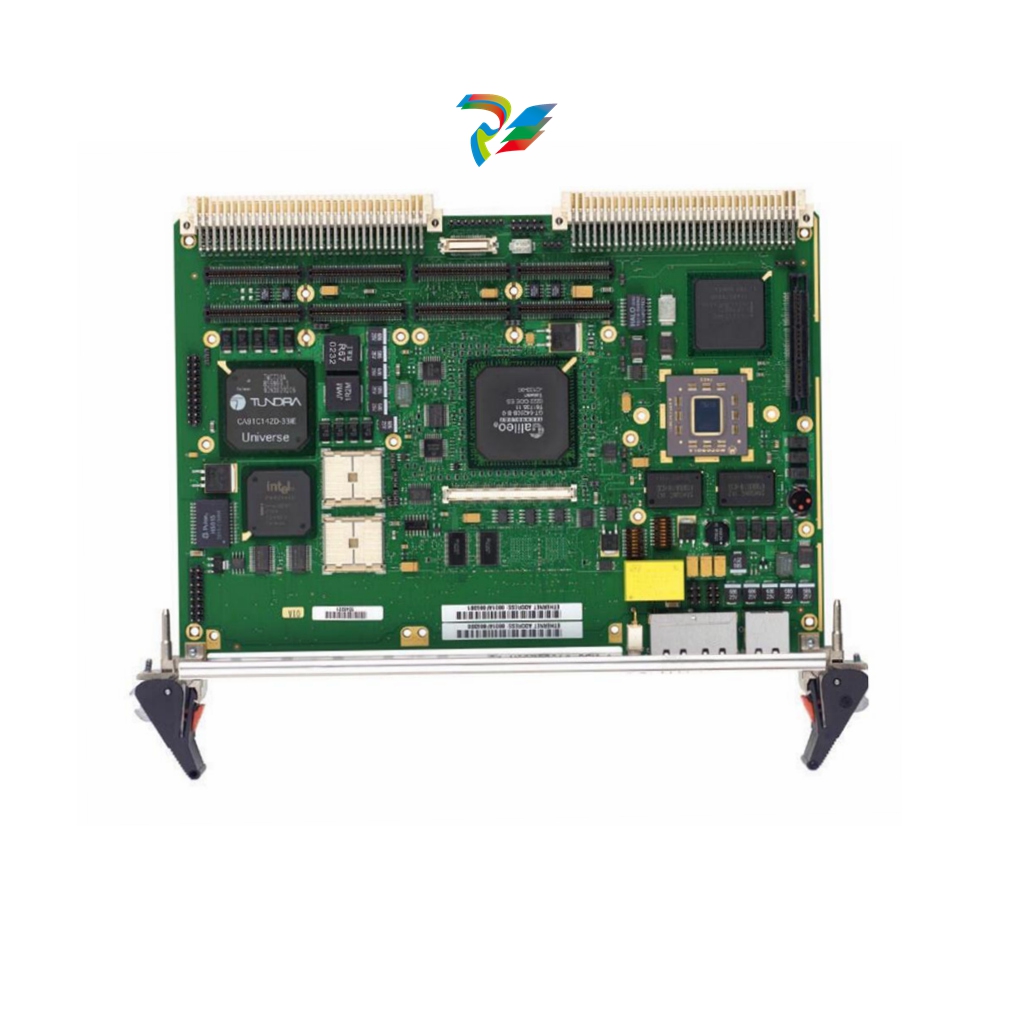
WARNING – Bodily injury. The device can be operated at high levels of pressure and with
aggressive media. Serious injury and/or considerable material damage can be caused if this
device is handled incorrectly.
NOTICE – Equipment damage or loss of data. When handling electronic parts and
assemblies, it is necessary that proper electrostatic discharge (ESD) precautions be taken
Wear an ESD wrist strap with a grounding cable and use an ESD shielded bag to protect
items removed. Clean only with a damp cloth.
1 Introduction
The PGC5000 Generation 2 Process Gas Chromatograph analyzer separates and measures the
individual components of gas or liquid samples. It automatically samples and analyzes process
streams using an appropriate interface to control analytical functions. This interface may be a Local
User Interface (LUI) that utilizes operational software located on the Master Controller, or it may be a
Remote User Interface (RUI) that has the same operational software on a PC. The term “user
interface” in this instruction refers to either the LUI or RUI, whichever applies to the system.
The PGC5000 Generation 2 analyzer is compatible with version 4.2.1 and later of the STAR Data
Management System.
Each analyzer has a temperature code (T-Rating) listed on the nameplate. This T-Rating indicates the
temperature classification of the area in which the analyzer has been designed to operate. T-Ratings
and area classifications for analyzer locations are determined and supplied by the customer.
The standard analyzer consists of a Master Controller and associated ovens. The configuration below
has the Master Controller connected to the ovens through an Ethernet switch.
Figure 1-1: Standard PGC5000 with ovens connected by switch
- YOKOGAWA
- Reliance
- ADVANCED
- SEW
- ProSoft
- WATLOW
- Kongsberg
- FANUC
- VSD
- DCS
- PLC
- man-machine
- Covid-19
- Energy and Gender
- Energy Access
- Renewable Integration
- Energy Subsidies
- Energy and Water
- Net zero emission
- Energy Security
- Critical Minerals
- A-B
- petroleum
- Mine scale
- Sewage treatment
- cement
- architecture
- Industrial information
- New energy
- Automobile market
- electricity
- Construction site
- HIMA
- ABB
- Rockwell
- Schneider Modicon
- Siemens
- xYCOM
- Yaskawa
- Woodward
- BOSCH Rexroth
- MOOG
- General Electric
- American NI
- Rolls-Royce
- CTI
- Honeywell
- EMERSON
- MAN
- GE
- TRICONEX
- Control Wave
- ALSTOM
- AMAT
- STUDER
- KONGSBERG
- MOTOROLA
- DANAHER MOTION
- Bentley
- Galil
- EATON
- MOLEX
- Triconex
- DEIF
- B&W
- ZYGO
- Aerotech
- DANFOSS
- KOLLMORGEN
- Beijer
- Endress+Hauser
- schneider
- Foxboro
- KB
- REXROTH
- YAMAHA
- Johnson
- Westinghouse
- WAGO
- TOSHIBA
- TEKTRONIX
- BENDER
- BMCM
- SMC
- HITACHI
- HIRSCHMANN
- XP POWER
- Baldor
- Meggitt
- SHINKAWA
- Other Brands
- UniOP
- KUKA
- IBA
- Beckhoff
- ADLINK
91
-
Beckhoff CX1100-0910 - Power Supply Module
-
Beckhoff C5210-0010 - Communication Module C5210
-
BECKHOFF KL1352 - Bus Terminal SET OF 2 FREE FAST SHIP
-
Beckhoff EL3058 - 8 x analog input single ended 4...20mA 85惟 shunt 12bit
-
Beckoff CX1100-0920 - UPS Module 24VDC (US SELLER) * *
-
BECKHOFF C6920-0000 - C69200000 PLC Moudule
-
Beckhoff CX5120-0115 - CPU controller module CX5120-0115
-
Unknown 15F5C1E-Y50A - Of Frequency Converters
-
Beckhoff AX5118-0000-0200 - Servo Drive HTP0
-
BECKHOFF AX5106-0000-0200 - Servo Drive
-
Beckhoff CX5240-0175 - Module (free) #U2327D YG
-
Beckhoff CP6607-0001-0000 - Compact PC Panel Economy Installation Operator 5,7 "
-
Beckhoff EP3744-0041 - 2022 EP37440041 Module
-
Beckhoff CP6209-0001-0020 - 6.5" PC Touch Screen Control Panel 24VDC
-
Beckhoff CX9020-0111 - /U900 +8x+2xEL3121+1x EL9410+3xEL1008+1x EL2008 Set
-
Beckhoff C6525-1030-0050 - Industrial PC
-
Beckoff CX1100-0920 - UPS Module 24VDC (US SELLER)
-
Beckhoff CX5010-0120 - CX5010 Processor Intel Atom Z510 B24
-
Siemens 6FC5203-0AF04-1BA1 - Operation Panel
-
Beckhoff CX5230-0175 - / 000029724 Embedded PC / Industrial PC on Rail
-
Beckhoff CP3916-0000 - industrielles Anzeige- und Bedienterminal
-
BECKHOFF CX1500-M310 - CX1000-N000 CX1000-0011 CX1000-C00L CX1100-0002 PLC Module
-
Beckhoff EL1872 - 16-channel digital input terminal
-
BECKHOFF EP2318-0001 - module
-
Beckhoff CX9020-0110 - Basic CPU Module
-
Beckhoff EL2564 - EtherCAT Terminal, 4-channel LED output, 5鈥?8VDC, 4A, RGBW
-
Beckhoff CX5130-0155 - /000105637 Automation Embedded PC
-
B&R 400 - Power Control Panel Rev D0 24 VDC
-
Beckhoff CX2020-0155 - module
-
Beckhoff CX9020-0115 - PLC Module
-
BECKHOFF EL6695 - PLC EL 6695
-
BECKHOFF EL7047 - PLC Modules
-
Beckhoff CX1000-0012 - Control HW 2.2 + CX1500-M310 + CX1000-C00L + CX1100-0002+
-
Beckhoff C6920-1039-0030 - control cabinet industrial PC CPU Celeron 1.90 GHz, 2 cores
-
BECKHOFF CX1100-0910 - PLC Module#
-
Beckhoff IL2301-B318-0000 - Coupler Box 4 Channel Digital Input |
-
Beckhoff CX7080 - Module
-
Beckhoff C6930-0060 - Industrial PC
-
Beckhoff CP7902-1060-0000 - Touchscreen 15 " CP7902
-
beckhoff CX9020-0111 - Controller module or UPS
-
Beckhoff CX8091 - PLC Module CX8091
-
Beckhoff C6640-1008-0030 - Control Cabinet Industrial PC
-
BECKHOFF CX1100-0920 - module
-
Beckhoff C9900-M921 - see pictures
-
BECKHOFF CP6829-0001-0000 - Touch Panel
-
BECKHOFF C6930-0060 - Industrial Computer
-
BECKHOFF CX8050 - PLC module
-
Beckhoff CP6202-0021-0020 - Touch Screen #
-
BECKHOFF AM3031-0C20-0000 - SERVO MOTOR
-
Unknown BCH1302N11A1C - Servo motor
-
Beckhoff EL2502 - 2-channel pulse width output terminal
-
Beckhoff EL6731 - Profibus Master / *Rev: 0025
-
Beckhoff CP3918-0010 - Control Panel
-
BECKHOFF CP2915-0010 - [24 MONTH WARRANTY] Control Panel
-
Beckhoff AX5203-0000-0202 - Servo Drive
-
Schneider TSXDSY64T2K - PLC OUTPUT MODULE
-
Beckhoff EP4174-0002 - Module-
-
Beckhoff IL2302-B318-0000 - Profibus Box
-
Beckhoff CP6709-0001-0000 - Touchpanel
-
BECKHOFF CX2030-0123 - Controller
-
Beckhoff CX9020-0111 - Processor Module
-
Beckhoff CX1020-0000 - CX Basic CPU Module
-
Beckhoff AX2003-AS - Servo Drive HTP0
-
Beckhoff C6240-1052-0040 - 4-086-06-3073 Industrial Computer CB1052-0003
-
Beckhoff EL1918 - 8 xTwinSAFE Input
-
Beckhoff AM8072-0R20-0000 - Servomotor
-
BECKHOFF AM8021-1B21-0000 - servo motor #T882 YS
-
Beckhoff EL6224 - 4 X Terminal IO-LINK
-
Beckhoff CX5140-0135 - embedded PC with Intel Atom processor 4 GB HW 3.6
-
Beckhoff CP7201-1000-0000 - Panel PC #
-
Beckhoff CX5130-0121 - Embedded-PC 4GB CPU Module HW 2.5 Industrial PC
-
Beckhoff AM8022-0D41-1002 - Servomotor
-
BECKHOFF CX2030-0130 - Module
-
BECKHOFF EL1872 - 16-channel digital input terminal
-
Unknown GXMMW.A203P33 - 1pc encoder
-
Beckhoff EL6631-0000 - EtherCAT Terminal 2-Port EL 6631
-
BECKHOFF C6925-0030 - Industrial Computer
-
Beckhoff CX8190 - A Module
-
BECKHOFF CX2040-0135 - CX2040-0135/000000927 CPU BASE MODULE i7 2715QE 2.1GHz --
-
BECKHOFF KL6023-0000 - Wireless adapter
-
Saia Burgess PCD7.F700 - PCD7F700 Communication Module
-
Beckhoff CX5130-0112 - CPU Module
-
BECKHOFF CX1020-N010 - CX1020-N000 CX1020-0111 CX1100-0004 EL2008 EL3064 EL4004
-
Beckhoff EP1819-0021 - A Module
-
Beckhoff CX2030-0120 - / 4gb with CX2100 0004
-
B&R X20-XC-0292 - Automation Powerlink Ethernet Bus Controller Module
-
Beckhoff BK3110 - One PLC Module
-
BECKHOFF KL3222 - PLC Module
-
BECKHOFF CX1500-M310 - CX1000-N000 CX1000-0011 CX1000-C00L CX1100-0002 PLC MODULE
-
Beckhoff CP3918-0010 - Control Panel
-
Beckhoff CX2030-0100-1002 - /4GB + CX2100 + CX2550 + CX2500-0060 + SSD
-
Beckhoff EP1816-0008 - PLC Module
-
Beckhoff CX5130-0112 - Module
-
Beckhoff Cx1500-m750 - CPU Hw: 1.4
-
BECKHOFF AX5112-0000-0200 - AX511200000200 Servo Driver
-
Beckhoff EL3751 - EtherCAT Terminal 1 Channel Analog Input Multifunction 24 Bit
-
Beckhoff CX1100-0002 - Power Supply Module
-
Beckhoff CP3916-1016-0010 - Control Panel
-
BECKHOFF CX9001-1101 - #NAME?
-
Beckhoff EP3174-0002 - EtherCAT Box Module
-
Beckhoff C6030-0070 - servo drive
-
Beckhoff CX2020-0120 - /4GB CPU, CX2100-0904, 3x EL6900, EL1904, 16GB Memory
-
BECKHOFF C6110 - BOX-PC 113608
-
BECKHOFF EK1914 - module #P
-
Beckhoff C6140 - Ipox IP-4GVI63 + CH7009A_DVI_TV + SIEMENS A5E00369843 + WD800AAJB
-
Beckhoff CX5020-0111 - controller Good quality
-
BECKHOFF C6015-0010 - / 6559380 ULTRA-COMPACT INDUSTRIAL PC ()
-
Beckhoff AX5203-0000-0200 - PLC module
-
Beckhoff EL2872 - 16-channel digital output terminal
-
BECKHOFF C3640-0000 - Panel Industrial PC 100/240VAC 128MB E0122L
-
Beckhoff CX8031 - Module
-
Beckhoff CX5020-0120-1002 - PLC module#
-
Beckhoff C6140 - M845B + SIEMENS A5E00369843 + C9900_A159_1 + AUTOMATA CAN PCI 1N
-
BECKHOFF AX5112-0000-0200 - Servo Drive*ie
-
B&R ECPA42-01 - Analog Output Module 4-Channel, +/- 10V Output Signal, 20mA Max
-
Beckhoff EL6631-0010 - PLC Module
-
BECKHOFF C6930-0070 - CONTROL CABINET INDUSTRIAL PC
-
BECKHOFF AX5112-0000-0200 - AX511200000200 Servo Driver
-
BECKHOFF EK9000 - Programmable Logic Controller Module EK9000 EK9000
-
BECKHOFF C6920-1028-0000 - Industrial computer
-
Beckhoff CX2030-0120 - controller Module
-
Beckhoff BX8000-0000 - Bus Terminal Controller HW 4.4
-
B&R 3NC154.60-2 - Positioning Module#
-
BECKHOFF CX1020-0122 - PLC module
-
Beckhoff AM3032-0D40-0000 - Servo Motor
-
BECKHOFF CX5020-0111 - CPU Module CX5020-0111
-
Beckhoff CB1051 - G5 Motherboard
-
BECKHOFF KL2641 - 1-channel relay output terminal

K-JIANG

Add: Jimei North Road, Jimei District, Xiamen, Fujian, China
Tell:+86-15305925923