
K-WANG


Honeywell OELD Smart Junction Box User Manual
Provide local visual status indication and Bluetooth low-energy interface, which can be configured and maintained through Bluetooth enabled mobile devices, certified by ATEX and IECEx, suitable for Zone 1 (gas) or Zone 21 (dust) hazardous areas, and the explosion-proof version also has cULus certification, suitable for Class I Zone 1 or Class II Zone 1.
There are 5 entrances (M25 or 3/4 "NPT depending on the version) and 3 certified plugs, while the Ex e version of the OELD only has 5 M25x1.5 entrances.
Honeywell OELD Smart Junction Box User Manual
Security Warning and Information
The installation must comply with the standards recognized by relevant national authoritative institutions, and reference should be made to EN 60079-14 and EN 60079-29-2 in the European region.
It is strictly prohibited to open the casing when powered on or when there may be explosive atmospheres present.
Operators need to be aware of the measures to be taken when the gas concentration exceeds the alarm level, and must not modify the product structure, otherwise it may render critical safety and certification requirements ineffective.
Only trained personnel are allowed to carry out internal operations of the product. Its measurement function has not obtained ATEX certification, and it is not allowed to rely on the backlight status indication of the OELD display screen for safety related operations. The equipment must not operate in an environment with an oxygen content exceeding 21%.
Special safety conditions for use (increased safety Ex e version)
Each terminal can be connected to a maximum of one single or multiple wires on either side, unless multiple wires are connected in an appropriate manner.
The insulation layer of the wire connected to the terminal should be suitable for the corresponding voltage and extend within 1mm of the terminal throat.
All used and unused terminal screws should be tightened to between 0.5Nm and 0.6Nm, and terminals can only be installed and wired using cables recommended by IECEx KEM 10.0093U.
Disposal and Environmental Protection
The product should be disposed of in accordance with local regulations, including materials such as the shell (aluminum alloy or 316 stainless steel), lid (aluminum alloy or 316 stainless steel, glass).
The product must be disposed of through appropriate WEEE disposal facilities and cannot be treated as general industrial or household waste.
Product Overview
Basic Introduction
OELD is a certified junction box for hazardous locations, suitable for detectors with 4-20mA output, and can be used in conjunction with Searchpoint Optima Plus or Searchline Excel series gas detectors.
Provide local visual status indication and Bluetooth low-energy interface, which can be configured and maintained through Bluetooth enabled mobile devices, certified by ATEX and IECEx, suitable for Zone 1 (gas) or Zone 21 (dust) hazardous areas, and the explosion-proof version also has cULus certification, suitable for Class I Zone 1 or Class II Zone 1.
There are 5 entrances (M25 or 3/4 "NPT depending on the version) and 3 certified plugs, while the Ex e version of the OELD only has 5 M25x1.5 entrances.
Structure and function
There are two grounding connection points and an electronic module with two pluggable terminal blocks inside the shell, used to connect the field and detector wiring.
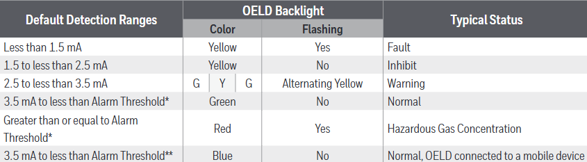
Featuring four-color backlighting (green, yellow, red, blue) and a customized 7-segment liquid crystal display (LCD), different backlight colors represent different states, such as green for normal operation or warning, red for alarm, etc.
Options
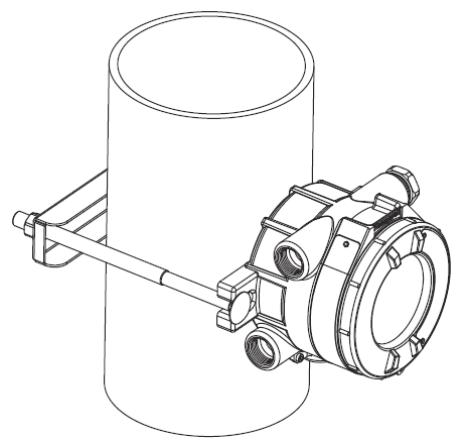
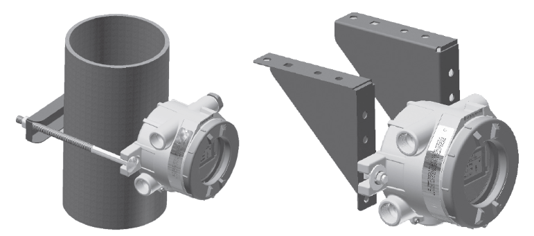
Including pipeline installation kit (1226A0358), which can install OELD on pipelines with diameters ranging from 2 "to 6" (50 to 150mm); Ceiling installation bracket kit (1226A0355), used for ceiling installation; Sun visor (94000-A-1006), made of 316 stainless steel, can protect OELD and related detectors from direct sunlight.
Installation related
Site selection and positioning
The placement of gas detectors should follow the recommendations of gas diffusion experts, process equipment experts, safety personnel, and engineering personnel, and record the protocol for determining the detector location.
Installation designers should refer to IEC/EN 60079-29-2 and other national practice standards, as well as the site selection recommendations for specific locations in the gas detector technical manual.
Mechanical Installation
OELD can be installed in various ways through integrated mounting pads, such as on flat walls Unistrut ® On the bracket, use the optional pipe installation kit to install on the pipeline or utility pole, or use the ceiling installation bracket kit to install on the ceiling.
When installing, it is necessary to consider the correct direction of the detector, ensure that the installation bolts are fully tightened, and use appropriate locking washers.
electrical installation
The detector can be installed directly or remotely to the OELD, and some detectors have corresponding junction boxes for remote installation.
The installation steps include removing the cover, taking out the electronic module, installing cable glands or conduit fittings, installing detectors (with different installation methods for different entrance versions), sealing unused cable entrances, making electrical connections, reinstalling the display module and cover, etc.
Electrical connection
Terminal block definition
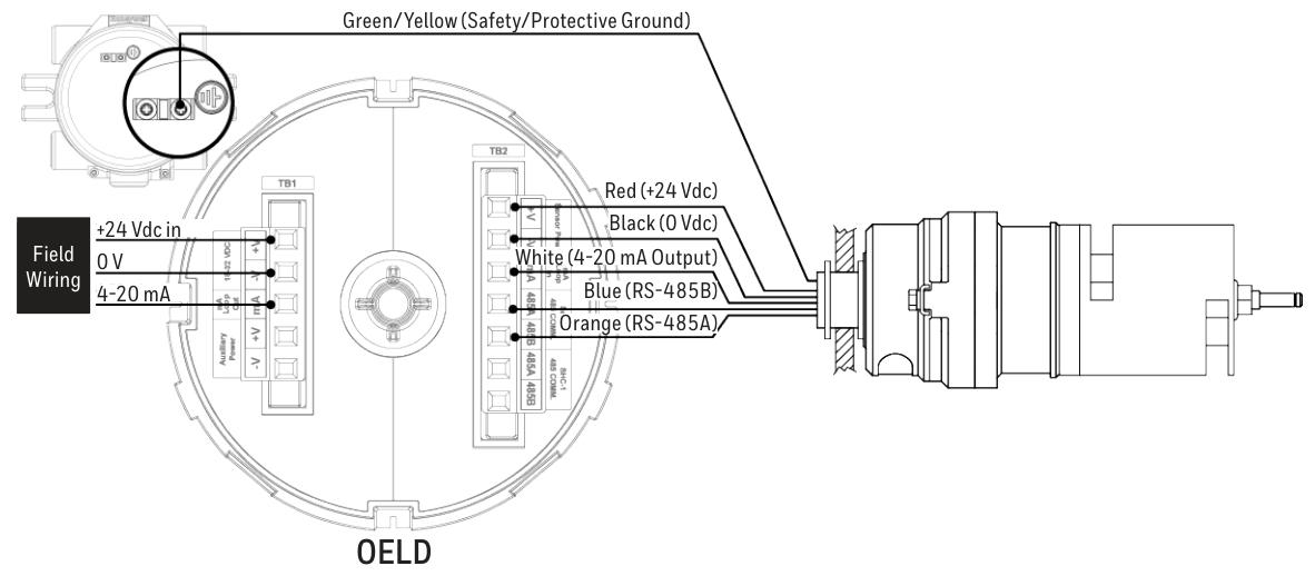
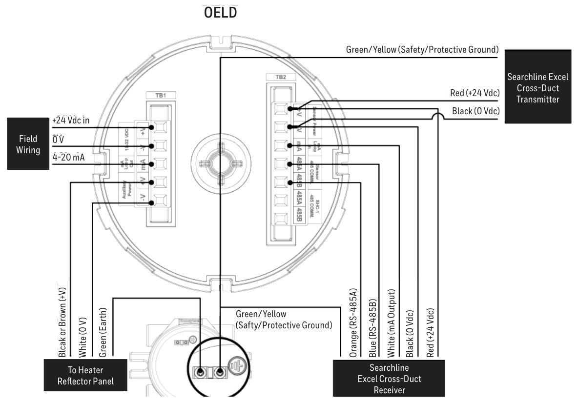
Terminal block 1 (TB1) and terminal block 2 (TB2) have different markings, colors, and functions for each terminal. For example, terminal 1 of TB1 is - V (black) and is used for auxiliary power supply.
The increased safety (Ex e) version uses terminal blocks of specific manufacturers and types, while the explosion-proof (Ex d) version is black and the increased safety version is green. They must not be mixed, otherwise the product certification will be invalidated.
Wiring diagram
Provided OELD and Searchpoint Optima Plus、Searchline Excel、Searchline Excel Cross-Duct(XD) Wait for the wiring diagram of the detector, as well as the connection method of the detector with the current sink and current source configuration.
Grounding connections should avoid grounding loops. The OELD has two internal grounding points, and the on-site cable shielding layer should be connected to the instrument grounding in the control room. The internal and external grounding points of the OELD have corresponding specifications and connection requirements.
Power supply and cables
The OELD requires a voltage supply of 18-32Vdc (nominal 24Vdc) with a maximum power consumption of 2W, taking into account the voltage drop caused by cable resistance to ensure the minimum required supply voltage at the detector.
The cable should be suitable for hazardous area classification and comply with relevant regulations. It is recommended to use industrial grade shielded field cables. The allowable wire size for terminals is 0.2-2.5mm ² (24-12AWG), and the rated wire temperature should be greater than 80 ° C. The terminal tightening torque should be 0.5Nm to 0.6Nm.
Configuration
Configurable parameters
Including local alarm indication threshold (can be set between 5 and 65% FSD, default 20% FSD), mA input level setting (to match the detector's mA output curve), and OELD universal display settings (such as full-scale range, measurement unit, gas name, etc.).
configuration process
Configure by running the OELD App on a mobile device, including steps such as launching the application, logging in, searching for nearby OELD units, selecting and confirming connections, etc.
After completing the configuration or changing the settings, the configuration should be read back and verified to ensure that the changes are correct.
Operation
Startup and self-test
The startup and self-test sequence takes about 60 seconds, during which display testing, backlight testing, internal hardware and memory checks, etc. will be performed. After completion, it will enter normal operating mode.
normal operation
During normal operation, the LCD backlight indicates the detector status based on the 4-20mA output of the detector, and different current ranges correspond to different backlight colors and flashing states.
The display screen displays gas concentration information (in graphical and numerical form) and other information during normal operation. At low temperatures, the refresh rate of the display screen will automatically decrease. At extremely low temperatures, the screen clarity may decrease, but it can return to normal after the temperature is restored.
communication model
Equipped with Bluetooth Low Energy (BLE) interface, it supports non-invasive connection with mobile devices running the OELD App, and can also communicate with specific detectors through RS-485 interface.
Honeywell Analytics SHC-1 handheld interrogator and SHC protection device can also be used to connect with relevant detectors, but attention should be paid to relevant warnings and precautions.
OELD Mobile Application
Installation and operation
The OELD mobile application can run on Android 4.3 (Jelly Bean) or higher operating systems that support Bluetooth Low Energy (BLE) and can be downloaded and installed from the Google Play Store.
The first launch requires reading the End User License Agreement, logging in or registering an account. Registration requires an Internet connection and at least one OELD device's QR code.
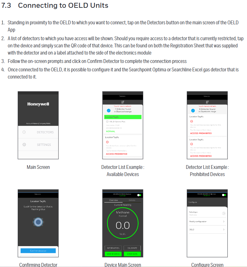
Connection and Configuration
Can connect to OELD devices that have already been registered to the user account. The connection steps include clicking on relevant buttons on the main screen of the application, selecting the device, scanning the QR code (if access to restricted devices is required), confirming the connection, etc.
Multiple parameters of the OELD device can be configured, as well as parameters of detectors such as Searchpoint Optima Plus and Searchline Excel connected to the OELD, and calibration operations can also be performed (specific detectors).
Maintenance and troubleshooting
maintenance
Regularly inspect the OELD and cables for physical damage, clean the glass windows with a damp cloth, and do not use solvents or abrasive cleaners. The OELD has no user repairable parts.
It is recommended to check the configuration and operation of the equipment at least once a year, and the gas detector connected to the OELD should be checked and calibrated according to its operating instructions.
The replacement of the display module requires following specific steps, including power-off, removing the cover and electronic module, replacing the module, etc. After replacement, it needs to be reconfigured.
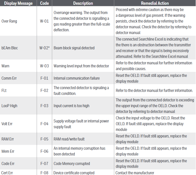
Malfunctions and warnings
Different display messages and codes correspond to different types of faults or warnings, such as "Over Rang" (W-01) indicating an over range warning, "Comm Err" (F-01) indicating an internal communication fault, etc., with corresponding remedial measures.
Specifications and ordering information
specifications
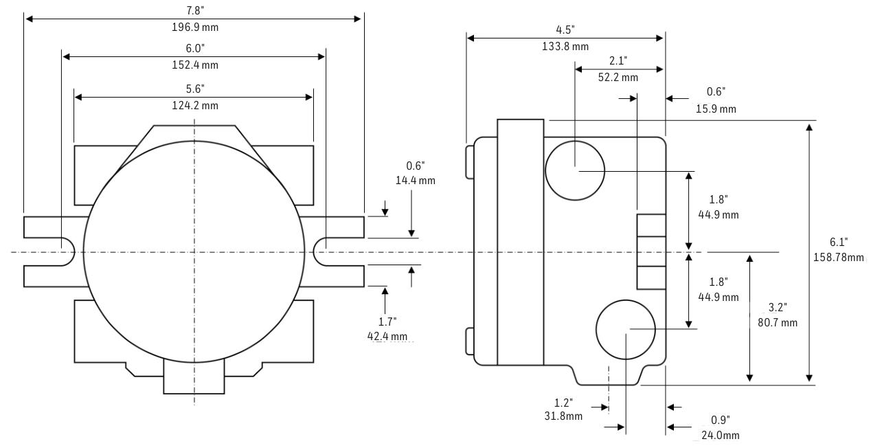
The material is marine grade aluminum alloy or 316 stainless steel (with 5-coated painted surface treatment), and the weight varies depending on the material. The size is 159x197x114mm, and the number and type of cable entrances vary depending on the version. There are corresponding terminals, storage and working temperatures, humidity, display information, visual indicators, power supply, interfaces, protection levels, and certifications.
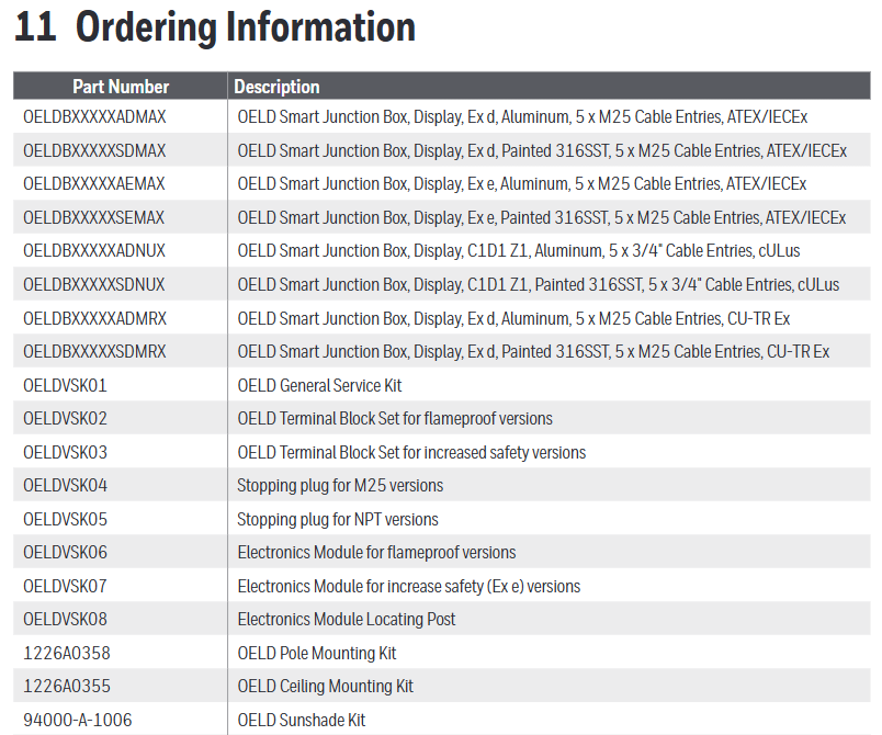
ordering information
We provide models and descriptions of different versions of OELD smart junction boxes and related accessories (such as universal service kits, terminal block groups, plugs, installation kits, sunshades, etc.). We warn that it is necessary to obtain service kits that match the OELD version, otherwise the product certification will be invalidated.
Certification and Warranty
Certification and Approval
Including EU conformity declaration, hazardous area certification (such as ATEX, IECEx, cULus, Inmetro, etc.), performance certification, wireless certification, etc. Different certifications have corresponding certificate numbers and scope of application.
Warranty Summary
Honeywell Analytics guarantees that the OELD will be free of component and process defects, repairable or replaceable under correct use for a period of 24 months from the date of shipment, excluding consumables, normal wear and tear, accidental damage, etc. Claims must be made within the warranty period.
- YOKOGAWA
- Reliance
- ADVANCED
- SEW
- ProSoft
- WATLOW
- Kongsberg
- FANUC
- VSD
- DCS
- PLC
- man-machine
- Covid-19
- Energy and Gender
- Energy Access
- Renewable Integration
- Energy Subsidies
- Energy and Water
- Net zero emission
- Energy Security
- Critical Minerals
- A-B
- petroleum
- Mine scale
- Sewage treatment
- cement
- architecture
- Industrial information
- New energy
- Automobile market
- electricity
- Construction site
- HIMA
- ABB
- Rockwell
- Schneider Modicon
- Siemens
- xYCOM
- Yaskawa
- Woodward
- BOSCH Rexroth
- MOOG
- General Electric
- American NI
- Rolls-Royce
- CTI
- Honeywell
- EMERSON
- MAN
- GE
- TRICONEX
- Control Wave
- ALSTOM
- AMAT
- STUDER
- KONGSBERG
- MOTOROLA
- DANAHER MOTION
- Bentley
- Galil
- EATON
- MOLEX
- Triconex
- DEIF
- B&W
- ZYGO
- Aerotech
- DANFOSS
- KOLLMORGEN
- Beijer
- Endress+Hauser
- schneider
- Foxboro
- KB
- REXROTH
- YAMAHA
- Johnson
- Westinghouse
- WAGO
- TOSHIBA
- TEKTRONIX
- BENDER
- BMCM
- SMC
- HITACHI
- HIRSCHMANN
- XP POWER
- Baldor
- Meggitt
- SHINKAWA
- Other Brands
- UniOP
- KUKA
- IBA
- Beckhoff
- ADLINK
-
ADLINK HPCI-14S12U - Industrial Control Backplane 12PCI Backplane PCI-14S Passive Backplane
-
ADLINK PCIe-GIE74C - image acquisition card 4-CH GigE Vision PoE+ Frame Grabber
-
ADLINK PCI-8164 - control card 4-Axis Advanced Motion Controller Board
-
ADLINK PCIe-U304 - 4 Port USB3 PCIe Frame Grabbers USB Screw Hole Card
-
ADLINK PCI-9112 - Multi-Function Data Acquisition Card DAQ Card
-
ADLINK PCI-7432 - 51-12013-0A50 4-CH Isolated Numérique I/O PCI Cartes Digital I/O Card
-
ADLINK PCA-6106P3-0C1 REV.C1 - backplane 6-Slot Passive Backplane Board
-
ADLINK PCI-7224 - 24-CH Opto-Isolated Digital I/O PCI Board
-
ADLINK CPCI-7433R(G) - Digital Input Board Rear I/O CompactPCI Card
-
ADLINK EBP-13E4 - 51-46703-0A30 Industrial PC Backplane Passive Backplane
-
ADLINK PCIE-HDV62 - Image acquisition card High Definition Video Frame Grabber
-
ADLINK EBP-13E4 - 51-46703-0A30 Industrial Backplane Board Passive Backplane
-
ADLINK 90111-B1 / CPCI-6770 - PCB CPU MODULE CompactPCI Single Board Computer
-
ADLINK PCI-7248 - DATA ACQUISITION PCI CARD 48-CH Parallel Digital I/O Board
-
ADLINK PCI-7230 - 51-12003-0a50 board PCI7230 32-CH Isolated Digital I/O Card
-
ADLINK PCI2A000CB - 51-20000-0B30 Multi-Function DAQ Card Baseboard
-
ADLINK PCI-8134-005 - 4-Axis Motion Controller Card
-
ADLINK PCI-7224 - 24-CH Opto-Isolated Digital I/O PCI Card
-
ADLINK PCI-7434 - 64-CH Isolated Digital Output Card
-
ADLINK PCI-8132 - motion control card 2-Axis Servo & Stepper Controller
-
ADLINK PCI-8134 - Motion Controller PCI Card 4-Axis Controller Board
-
ADLINK PCI-8164 - Motion Control Card 51-12406-0A40 4-Axis Controller
-
ADLINK 51-12001-0C20 - Circuit Board Data Acquisition Interface Module Hardware
-
ADLINK NuPR0-840 - industrial control motherboard Full-Size PICMG CPU Board
-
ADLINK PCI-7444 - 51-12023-0A10 card 128-CH Isolated Digital Output Board
-
ADLINK PCI-1612B - data acquisition card 4-Port RS-232/422/485 Serial Communication Card
-
ADLINK PCI-6208V 009 - 8/16-CH 16-Bit Analog Output Cards PCB-I-E-482=6BX3
-
ADLINK NUPRO-935A/LV - industrial control motherboard Full-Size PICMG SBC Board
-
ADLINK PCI-9114DG - Multi-Function DAQ Card Data Acquisition PCI Card
-
ADLINK ACL-7130 - Data acquisition card Isolated Digital I/O Board
-
ADLINK ABX-6300D-4E1-BP - board ABX6300D4E1BP Video Interface Expansion Card
-
ADLINK CPCI-6940 - CPCI-6940/D1539/M16-0(EA)-000E 6U CompactPCI Processor Board
-
ADLINK NuPRO-760 - industrial control motherboard Half-Size PICMG SBC CPU Board
-
ADLINK IMB-M42H (G)-0020 - industrial control motherboard LGA1155 Micro-ATX Mainboard
-
ADLINK RTV-24 / PCI-MP4S - 51-12519-1C30 4-Channel Real Time Video Capture Board
-
ADLINK PCI-8134 - 4-Axis Servo & Stepper Motion Controller Card
-
ADLINK MXC-6101D - V.PC000.002.ST.00 Box PC Configurable Embedded Computer
-
ADLINK PCI-8134A - 51-12421-0A10 Motion Control Card 4-Axis Controller Card
-
ADLINK DIN-100S / DIN-100SA1 - Technology SCSI-II TB 100-PIN Terminal Block Board
-
ADLINK DIN-812M001 / DIN812M001 - 51-14034-0A1 51140340A1 Terminal Module Breakout Interface
-
ADLINK PCI-8164 - Servo motion control 4-Axis Advanced Controller Card
-
ADLINK PCIe-GIE64 - Acquisition card GigE Vision PoE+ Frame Grabber
-
ADLINK M-302 - Industrial control motherboard ATX PC Board Mainboard
-
ADLINK PCI-8134 - Motion Controller PCI Card 4-Axis Controller Board
-
ADLINK PCI-RTV24 - Image capture card Analog Video Frame Grabber
-
ADLINK PCI-8102 - Motion control card 2-Axis Servo & Stepper Controller Board
-
ADLINK PCI-9112 REV.B1 - Card Multi-Function Data Acquisition Card
-
ADLINK HSI-DI32-M-N / HSL-TB32-M-DIN - Discrete I/O MODULE Distributed Automation Module System
-
ADLINK PCI-7296 - IO card REV.A3 96-CH Parallel Digital I/O Card
-
ADLINK DIN-814P-A4 / 814Y - terminal board Motion Control Interface Block
-
ADLINK DIN-814P-A4 - 51-14056-0A10 PCB-I-E-2736=ZA01 Screw Terminal Board Breakout
-
ADLINK M-322 - motherboard Industrial Control Computer Mainboard
-
ADLINK NUPRO-406 REV:B1 - industrial control motherboard Full-Size PICMG CPU Board
-
ADLINK AMP-204C - card DSP-Based 4-Axis Advanced Pulse-Train Controller
-
ADLINK HPCI14S REV.B1 - industrial computer baseboard 14-Slot Passive Backplane
-
ADLINK PCI-7250 - 8-CH Relay Output & 8-CH Isolated DI PCI Card
-
ADLINK EBP-13E2 - baseplate Passive Backplane Industrial Computer Chassis Board
-
ADLINK LPCI-3488A - PCI-GPIB card 51-12801-0A30 acquisition card IEEE-488 Interface Board
-
ADLINK PCI-6216V-GL - 51-12201-0C30 16-CH 16-Bit Voltage Analog Output Card
-
ADLINK ACL-8454 - 16-CH Isolated Digital I/O & 4-CH Counter Card
-
ADLINK HPCI-9S7U - backplane Passive Backplane Compatible with NuPRO-A301 852 841 842
-
ADLINK DAQ-2010-007 - Simultaneous-Sampling Multi-Function Data Acquisition Card
-
ADLINK MP-C154 - 51-64205-0A10 Motion Control Card 4-Axis Controller Board
-
ADLINK MXE-202/mSSD16B/WiFi-BT - Matrix Rugged I/O Platform Embedded Fanless Computer
-
ADLINK CM-920-R-17 - PC/104-Plus Single Board Computer Module Intel Celeron M
-
ADLINK PCI-7250 NSMP - 8-CH Relay Output & 8-CH Isolated DI Card
-
ADLINK PCI-8164 - 4-Axis Motion Controller PCI Card W/ Cable and Breakout Box
-
ADLINK EMX-100 - Ethernet-based 4-axis Motion Controllers Distributed Motion Module
-
ADLINK PCI-8134A - Press control card 4-Axis Motion Controller Board
-
ADLINK M-845EG REV:3.2 - industrial motherboard Pentium 4 Socket 478 Micro-ATX
-
ADLINK PCI-9114A Rev A2 DG - card High-Resolution Multi-Function Data Acquisition Board
-
ADLINK IEC-915GV - REV 1.1 Industrial motherboard Socket 478 CPU Board
-
ADLINK PCI-9111DG(G) - Data Acquisition Card Multi-Function DAQ Card
-
ADLINK HPCI-15S10 REV:B2 - Industrial computer base plate Passive Backplane Board
-
ADLINK NuPR0-840 / NuPR0-840DV - industrial control motherboard Full-size PICMG CPU Board
-
ADLINK RTV-24 / PCI-MP4S - 51-12519-1C30 4-Channel Real Time Video Capture Board
-
ADLINK NUPRO-780 - industrial control motherboard Pentium III Single Board Computer
-
ADLINK PCI-7296 - 0050 card 96-CH Opto-Isolated Parallel DIO Card Set
-
ADLINK NUPRO-780 - industrial control motherboard PICMG Full-Size SBC
-
ADLINK PCI-7248 - 51-12006-0A3 002 Pci 7248 48-CH Parallel Digital I/O Card
-
ADLINK cPCI-6626 - 6U CompactPCI 2.0 Blades i7-2710QE PCB-I-E-2570=9N41
-
ADLINK MXC-6322D(G) - Industrial Fanless Computer
-
ADLINK cPCI-8168-004 - CompactPci NulPC Motion Control Board 51-36402-0A3
-
ADLINK CPCI-7300[G] - COMPACTPCI Digital I/O Card Data Acquisition
-
ADLINK CPCI-6626/2710/M4G - COMPACTPCI COMPUTER BOARD
-
ADLINK cPCI-8168-009 - cPCI NulPC Motion Control Board
-
ADLINK cPCI-6626/2710/M4G - VME CPU Board Computer Board
-
ADLINK CPCI-R6200(G)-0040 - COMPACTPCI CONTROL BOARD
-
ADLINK CPCI-3840/PM18/M1G(G)-3650 - COMPACTPCI CPU Module Single Board Computer
-
ADLINK cPCI-7248 - 48-CH Opto-22 Compatible Digital I/O Module
-
ADLINK DLAP-211-JNX - NVIDIA Jetson Xavier NX Edge AI Inference Platform
-
ADLINK cPCI-3544 - Series 4-Port RS-422/485 Isolated Serial Communications Card
-
ADLINK CM1-86DX3 - PC/104 SBC Stanley Vortex86DX3 CPU 2GB Ram
-
ADLINK DLAP-211-JNX - NVIDIA Jetson Xavier NX Edge AI Inference Platform
-
ADLINK cPCI-3544 - Series 4-Port RS-422/485 Isolated Serial Communications Card
-
ADLINK CM1-86DX3 - PC/104 SBC Stanley Vortex86DX3 CPU 2GB Ram
-
ADLINK PCI-7433 - switch value acquisition card Isolated Digital Input Card
-
ADLINK PCI-9112 - 51-12252-0D20 Multi-Function Data Acquisition Card
-
ADLINK NUPRO-A301 REV:1.4 - industrial control motherboard PICMG Full-Size SBC
-
ADLINK 51-18502-0A10 - Frame Grabber Image Acquisition Interface Card
-
ADLINK PCI-7296 - 51-12009-0A50 PCB-I-E-925=6DX1 96-CH Parallel Digital I/O Board
-
ADLINK PCI-8132 GP A2 - Motion Control Card 2-Axis Servo & Stepper Controller
-
ADLINK PCI-7442 - switch quantity card data acquisition card 64-CH Isolated Card
-
ADLINK HPX-13S4 - baseboard PICMG 1.3 Passive Backplane Chassis Baseplate
-
ADLINK NuPRO-590 / NTC-567-ZM-F36 - Single Board Computer PCB-I-E-1853=9L21 Half-Size SBC
-
ADLINK PCIe-8332 - 16-axis plate Motion Control Hardware Card
-
ADLINK NuPRO-775 REV.B1 - motherboard Pentium 4 Full-Size PICMG SBC
-
ADLINK PXI-3920 - Embedded Controller 3U PXI cPCI System Intelligence Board
-
ADLINK PCI-8134 - driver card motion control card 4-Axis Controller Board
-
ADLINK HSL-DI32-M-N-011 / HSL-TB32-M-DIN - Digital Input & Base Module PLC Distributed I/O System
-
ADLINK PCI-6216V-206 / PCI-208V 009 - 16 CH 16bit analog output card
-
ADLINK NuPro-E330 - 51-41805-0A20 PCB Single Board Computer Host Board
-
ADLINK PCI-1622C - Card 8-Port RS-232/422/485 PCI Serial Communication Board
-
ADLINK PCIe-7432 - 51-18402-0A10 Carte PCIe Avec Plage D'Entrée Élevée Isolated DIO Card
-
ADLINK PCI-7250 - PCI Acquisition Card 8-CH Relay Output Isolated DI Card
-
ADLINK PCI-7230 - 32-CH Isolated Digital I/O Card
-
ADLINK PCI-8164 - PCB 4-Axis Motion Controller Card
-
ADLINK PCI-7854 - Collection card High-Speed Link Distributed Motion Controller
-
ADLINK NuPRO-935A/LV - industrial control computer motherboard Full-Size PICMG SBC
-
ADLINK IMB-M40H - motherboard IH61-AA4 1155 LGA1155 Micro-ATX Mainboard
-
ADLINK PCI-7248 - Linhua 51-12006-0A40 48-CH Parallel Digital I/O Card
-
ADLINK HPCI-14S12U - Linhua industrial computer baseboard Passive Backplane
-
ADLINK PCI-8132 Rev.A2 - 2-Axis Servo & Stepper Motion Controller Card
-
ADLINK ACL-8111 - ISA card Multi-Function DAQ Card
-
ADLINK ACL-8111 - ISA card Multi-Function Data Acquisition Board
-
ADLINK PCI-7200 REV.A3 - Digital I/O card 12MB/s High-Speed Parallel Digital I/O
-
ADLINK PCI-7296 REV.A3 - 96-CH High-Density Opto-Isolated DIO Card
-
ADLINK PCI-7434 - 64-CH Isolated Digital Output Card

K-JIANG

Add: Jimei North Road, Jimei District, Xiamen, Fujian, China
Tell:+86-15305925923