
K-WANG


OMRON FQM1 Motion Controller Instruction System
OMRON FQM1 Motion Controller Instruction System
The OMRON FQM1 series flexible motion controller, as a core component in the field of industrial automation, provides a solid foundation for modern FA (factory automation) systems with its powerful instruction set and flexible system architecture. This article is based on the instruction reference manual of the FQM1 series (covering FQM-1-CM002, FQM1-MMP22, and FQM1-MMA22 models), and deeply analyzes its technical specifications, safety guidelines, version evolution, and programming instruction details, aiming to provide a detailed professional technical guide for electrical engineers and system designers.
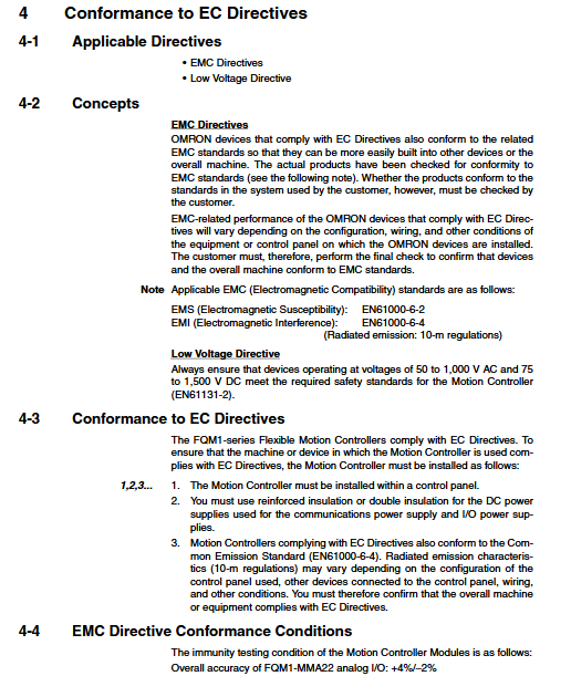
System Overview and Security Standards
The FQM1 series controller consists of a coordination module and a motion control module, designed to meet complex motion control and logic control requirements. As a professional industrial equipment, its operation and maintenance are strictly limited to professionals with electrical engineering knowledge. The manual clearly defines safety risks through three levels: "DANGER", "Warning", and "Caution".
At the operational level, the manual emphasizes several crucial safety principles:
Electric shock protection: It is strictly prohibited to disassemble modules or touch terminals while powered on, as this may cause serious electric shock injuries.
External safety circuit: Given that the controller may experience output abnormalities (such as output locking in ON or OFF state) due to hardware failures or self diagnostic errors, the system design must include external physical safety circuits (such as emergency stop circuits, interlock circuits) to ensure safe shutdown of the system in the event of controller failure.
Grounding requirements: During installation, a grounding resistor of less than 100 Ω must be connected, especially when the functional grounding of the power unit is short circuited to the grounding terminal of the line. Good grounding must be ensured to prevent electric shock or interference.
In addition, the manual also provides detailed environmental precautions for operation, prohibiting operation in direct sunlight, condensation, corrosive gases, or strong electromagnetic fields. It emphasizes the use of crimping terminals during wiring to avoid direct connection of exposed stranded wires and prevent short circuits or fire risks.
Unit version and functional evolution
The FQM1 series controllers undergo iteration and hardware upgrades through the "unit version" management function. The version number is usually marked to the right of the batch number on the module nameplate. From version 2.0 to 3.3, the controller has undergone significant feature enhancements:
Version 3.1: The main improvement lies in obtaining UL certification, which requires the configuration of specific relay units and connecting cables to comply with safety standards.
Version 3.2: Introduced multiple key features. In electronic cam mode, PULS (886) command supports pulse output zero crossing (CW/CCW direction) and can automatically calculate the pulse output frequency. In addition, a cyclic refresh zone has been added for data exchange between modules, and support for CJ series units has been expanded, such as analog output units (CJ1W-DA08V, etc.) and position control units. In the system settings, the output range of the 20MHz clock frequency can be extended to 1 Hz to 1 MHz, greatly improving the low-frequency control accuracy.
Version 3.3: The focus has been on enhancing compatibility with servo motors, starting to support OMNUC G-series absolute encoders, and further expanding the mounting capability of CJ series special I/O units, including analog input/output units and hybrid modules.
These version differences require engineers to verify module versions when designing systems to ensure that software instructions match hardware functionality.
Fundamentals of Programming and Data Structures
The program capacity of FQM1 varies depending on the module type, and the coordination module (CM002) has 10K steps. Programming adopts ladder logic, and instruction execution involves bit processing and word processing. Understanding data formats and addressing methods is a prerequisite for efficient programming.
1. Data format
FQM1 supports multiple data formats, including unsigned binary, signed binary, BCD code, and floating-point numbers. Floating point numbers follow the IEEE754 standard, support single precision and double precision operations, and are widely used in high-precision mathematical operation instructions. Binary negative numbers are represented using complement codes, which is crucial for understanding the results of arithmetic operations.
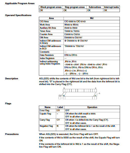
2. operands and addressing
Instructions typically include source operands, target operands, and control operands.
Bit address: Specify the word address and bit number (such as 0001.02).
Indirect addressing: Supports binary mode (@ D) and BCD mode (* D). For example, @ D00300 represents using the content of D00300 as a new address pointer, greatly enhancing the flexibility of the program.
Constant input: Supports decimal (&prefix) and hexadecimal (# prefix), but in timer/counter settings, constant input must conform to the BCD code range.
3. Differential instruction
To capture the edge changes of the signal, FQM1 provides non differential, rising edge differential (@ prefix), and falling edge differential (% prefix) instructions. The rising edge differentiation is only executed once when the execution condition changes from OFF to ON, while the falling edge differentiation is the opposite. This plays a crucial role in handling trigger signals and avoiding duplicate execution.
Detailed Explanation of Core Instruction Set
The instruction set of FQM1 is large and finely classified. The following focuses on analyzing the key instruction categories.
1. Sequential input instructions
This is the cornerstone of ladder diagram programming. LD (load), AND (AND), OR (OR), and their NOT forms form the basis of logical judgment.
Logical block connection: The AND LD and OR LD instructions are used to connect complex logical blocks. The manual states that when using these instructions to connect multiple logical blocks, the number of LOAD instructions must be one more than AND LD/OR LD instructions, otherwise it will cause programming errors.
Bit test instructions: TST (350) and TSTN (351) allow testing of specific bit states in specified words like LD/AND/OR, and support DM area operations, solving the limitation of traditional contact instructions that cannot directly read DM areas.
Conditional on-off: The UP (521) and DOWN (522) instructions simplify differential logic and can generate single cycle pulses without occupying working bits, which helps streamline program steps.
2. Sequential output instructions
Output and hold: The OUT instruction directly outputs the state of the execution condition, while the KEEP (011) instruction implements the function of a latch relay. Set when Set input is ON, reset when Reset input is ON. It should be noted that in the interlock program segment, the KEEP instruction can maintain the state, while the ordinary self holding circuit will reset due to the release of the interlock.
Set and Reset: The SET and RSET instructions are independent of execution conditions and only change the bit state when the condition is ON, and remain unchanged when it is OFF. In contrast, the SETB (532), RSTB (533), and OUTB (534) instructions not only operate on the DM location, but also support immediate refreshing of variants (! Prefix), which can directly update physical output terminals and shorten response time.
3. Sequential control instructions
Interlock: IL (002) and ILC (003) must be used in pairs. When the IL condition is OFF, the program segment output between IL and ILC is forcibly reset (OUT becomes OFF, TIM is reset), but the SET/RSET and counter states remain unchanged. This is different from the JMP instruction, as all output states in the program segments skipped by JMP remain unchanged.
Jump: JMP (004)/JME (005) pairs are used to skip program segments. When the JMP condition is OFF, a jump occurs and the skipped instruction is not executed, resulting in a shorter loop time. CJP (510) jumps when the condition is ON, while CJPN (511) is similar to JMP. Note that jump instructions must be paired and within the same task.
Loop: FOR (512)/NEXT (513) forms a loop structure, and the value of N determines the number of loops. The BREAK (514) instruction can be used to forcefully exit a loop. The nested depth of the loop is limited to 15 layers and cannot cross tasks.
4. Timer and counter instructions
FQM1 provides multiple precision timers:
TIM: Standard 100ms countdown timer with an accuracy of -0.01s~0s.
TIMH (015): High speed 10ms countdown timer.
TMHH (540): Ultra high precision 1ms countdown timer, whose current value refreshes every 1ms through interrupts, suitable for microsecond level control requirements.
CNTR (012): Reversible counter with up and down inputs, suitable for scenarios such as position accumulation.
The manual specifically states that in the jump program segment, the timer that is currently counting will continue to count; In the interlock program segment, the timer will be reset. This is because the IL instruction forces a reset of the output state, while JMP only skips execution logic.
5. Data processing and operation instructions
Although the source data in this article does not fully cover all operation instructions, the full picture can be seen from the instruction list.
Comparison instructions: In addition to basic CMP, there are also symbol comparison instructions (such as LD>, AND<=, etc.) as well as table comparison (TCMP) and block comparison (BCMP). The block comparison BCMP (068) can determine whether the source data is within the preset upper and lower limits, greatly simplifying the logic of multi interval judgment.
Data movement: The MOV instruction family supports the transfer of words, bits, and digits. XCHG (073) is used for data exchange, XFER (070) is used for block transfer, and BSET (071) is used for memory filling.
Mathematical operations: Supports BCD code and binary arithmetic operations, including carry processing. Floating point operation instructions (such as+F, * F) comply with the IEEE754 standard, support trigonometric and exponential logarithmic operations, and meet the requirements of complex algorithms.
Logical operations: Instructions such as ANDW, ORW, XORW are used for bitwise logical operations on word data, commonly used for masking or extracting status words.
Advanced features and system maintenance
FQM1 has a comprehensive self diagnostic function. FAL (006) is used for non fatal error alarms, and the system continues to operate; FALS (007) indicates a fatal error and will stop the controller from running. These instructions, in conjunction with the flag bits in the auxiliary area (Area A), provide convenience for troubleshooting.
In terms of data backup mechanism, the user program and some DM areas of the coordination module are backed up through Flash memory, while some DM areas and error logs of the motion control module rely on supercapacitors. At 25 ° C, the capacitor backup time can reach about 100 hours, but as the ambient temperature increases and the lifespan increases, the backup time will be shortened. Therefore, for data recovery after long-term power outages, it is recommended to store key parameters in the DM area address supported by Flash (D20000-D32767).
- YOKOGAWA
- Reliance
- ADVANCED
- SEW
- ProSoft
- WATLOW
- Kongsberg
- FANUC
- VSD
- DCS
- PLC
- man-machine
- Covid-19
- Energy and Gender
- Energy Access
- Renewable Integration
- Energy Subsidies
- Energy and Water
- Net zero emission
- Energy Security
- Critical Minerals
- A-B
- petroleum
- Mine scale
- Sewage treatment
- cement
- architecture
- Industrial information
- New energy
- Automobile market
- electricity
- Construction site
- HIMA
- ABB
- Rockwell
- Schneider Modicon
- Siemens
- xYCOM
- Yaskawa
- Woodward
- BOSCH Rexroth
- MOOG
- General Electric
- American NI
- Rolls-Royce
- CTI
- Honeywell
- EMERSON
- MAN
- GE
- TRICONEX
- Control Wave
- ALSTOM
- AMAT
- STUDER
- KONGSBERG
- MOTOROLA
- DANAHER MOTION
- Bentley
- Galil
- EATON
- MOLEX
- Triconex
- DEIF
- B&W
- ZYGO
- Aerotech
- DANFOSS
- KOLLMORGEN
- Beijer
- Endress+Hauser
- schneider
- Foxboro
- KB
- REXROTH
- YAMAHA
- Johnson
- Westinghouse
- WAGO
- TOSHIBA
- TEKTRONIX
- BENDER
- BMCM
- SMC
- HITACHI
- HIRSCHMANN
- XP POWER
- Baldor
- Meggitt
- SHINKAWA
- Other Brands
- UniOP
- KUKA
- IBA
- Beckhoff
-
Basler Electric DECS-250-CN1SN1N Automatic Voltage Regulator for Generator Excitation Control
-
ADLINK CPCI-6860A - 51-31310-OB10 industrial motherboard CompactPCI SBC
-
ADLINK AmITX-SL-G-H110 - 51-7A104-0A30 Mini-ITX Industrial Motherboard
-
ADLINK PXI-2005-003 - CPCI Industrial PC Data Acquisition Card Multi-Function DAQ
-
ADLINK DININ-814M - 51-14032-0A3D SCSI-100P cable connection Interface Terminal Board
-
ADLINK CPCI-3920NA/C2D15/M1G - 3U CompactPCI Intel Core 2 Duo Single Board Computer
-
ADLINK PCIE-8560 - 51-18014-0A20 Communication Card High Speed DAQ
-
ADLINK PCI-C154+ - Motion Control Card 4-axis Motion Controller Board
-
ADLINK PCI-RTV24 - image capture card Analog Video Frame Grabber
-
ADLINK NuPRO-842LV/P - 51-41360-0B30 Industrial Motherboard CPU Board
-
ADLINK cBP-3208/3208R - CPCI Board 3U 8-Slot CompactPCI Backplane
-
ADLINK PCI-8164 - 4-Axis Motion Controller PCI Card 51-12406-0A40
-
ADLINK PCIe-GIE64+ - 4-CH GigE Vision PoE+ Frame Grabber Video Capture Card
-
ADLINK CPCI-6860 / 6860A - CompactPCI Dual Xeon Single Board Computer
-
ADLINK IEC-915GV - REV 1.1 Industrial motherboard CPU Board
-
ADLINK ND-6520 - Technology RS-232 to RS-422RS-485 Converter NuDAM Module
-
ADLINK RTV-24 / PCI-MP4S - 51-12519-1C30 4-Channel Real Time Video Capture Board
-
ADLINK cPCI-6910 / cPCI-6910AM/M1G - cPCI-6910AM/DXL16/M1G/S80G(G)-3120 BOARD CompactPCI SBC
-
ADLINK NUPRO-A40H - Linghua 51-41807-1A30 Industrial Control Computer Motherboard
-
ADLINK USB-3488A - USB to GPIB INTERFACE USB-3488A(G) Controller Module
-
ADLINK PCI-8134A - motion control card 4-Axis Controller Card
-
ADLINK PCI-7432 - Board 32-Channel input / 32-output Isolated Digital I/O PCI Card
-
ADLINK PCI-8134A - 51-12421-0A10 motion controller card tested
-
ADLINK LPCIe-7230 - 32 CH Isolated Input/output Card 2 Interrupts Low Profile PCIe
-
ADLINK NuPRO-E340 - industrial computer motherboard 51-47807-0A30 PICMG 1.3 SHB
-
ADLINK PCI-7434 - High-speed Digital Acquisition Card 64-CH Isolated DO Card
-
ADLINK NuPRO-E330 - 51-41805-0A20 Indsutrial Board SHB Single Board Computer
-
ADLINK PCI-7248 - OPTO-22 48 CHANNEL DIO DIGITAL TTL/DTL I/O 51-12006-0A40 GP
-
ADLINK PCI-8134 - Motion control card 4-Axis Controller Card
-
ADLINK AMP-208C - Movimiento Control Tarjeta 51-12420-1A20 W/Expansión & Breakout
-
ADLINK PCI-8164 - 51-12406-0A40 PCB Board 4-Axis Motion Controller Card
-
ADLINK DIN-68Y-SGII / DIN-68M-J3A - Terminal Board Connector Interface Block
-
ADLINK PCIe-7432 - Technology 51-18402-0A10 PCIe Card With High Input Range
-
ADLINK PCI-8144 / PCI-8144N - Motion control card 4-Axis Stepper Controller Card
-
ADLINK HSL-HUB3/REPEATER - HIGH SPEED LINK EXTENSION MODULES Distributed Hub Module
-
ADLINK ND-6017 - Data Logging + Acquisition 8CH A/D input Mod NuDAM Module
-
ADLINK LPCIe-7250 - data acquisition card Low Profile 8-CH Relay Output Card
-
ADLINK PCI-7432 - I/O card 64-CH Isolated Digital Input Output PCI Card
-
ADLINK IMB-M43H - industrial control computer motherboard Q87 Chip Micro-ATX
-
ADLINK MP-C154 - Motion control Card 4-Axis Motion Controller Board
-
ADLINK PCI-RTV24 - image capture card Video Frame Grabber Card
-
ADLINK PCI-7250 - 8-CH Relay Output & 8-CH Isolated DI Card
-
ADLINK PCI-6308V - 8-CH 12-Bit Isolated Analog Output PCI Card PCB-I-E-1148=6EX2
-
ADLINK PCI-7248 - capture card 48-CH Opto-22 Compatible DIO Card
-
ADLINK HSL-AI16A02-M-VV - Analog Input Output Distributed Module
-
ADLINK NuPRO-A301 - Rev:1.4 NUPRO-A301 PICMG Full-Size Single Board Computer
-
ADLINK PCI-6208V-GL - 8-CH Voltage Analog Output PCI Card
-
ADLINK PCI-8134A - 51-12421-0A10 4-Axis Motion Controller Card
-
ADLINK MNET-S23 - TECHNOLOGY MNET S23 - SERVO DRIVER CONTROL MODULE
-
ADLINK M-342 - ATX I3 I5 I7 Q67 Industrial Motherboard
-
ADLINK NUPRO-780 - Industrial Motherboard CPU Board PICMG SBC
-
ADLINK MP-C154 / MP-C152 - 4-Axis Motion Control Card Pulse-Train Controller
-
ADLINK NuPRO-935A/LV10B0 - Motherboard 51-41802-0A10 GP w/RAM Industrial Control Board
-
ADLINK MP-C154 - Motion control card 4-Axis Motion Controller Mainboard
-
ADLINK PCI-7250 - PCI Acquisition Card 8-CH Relay Output Isolated DI Card
-
ADLINK ACL-7124 - Technology Inc.24 DIO Card Digital Input Output Card
-
ADLINK PCI-8554 A2 - Timer/Counter Data Acquisition Card
-
ADLINK DIN-825-GP4 - Terminal Block Interface Board Breakout Module
-
ADLINK NuPR0-761 - REV:1.1 Industrial motherboard Full-Size PICMG SBC
-
ADLINK MXE-1401/M8G (G) - Matrix Fanless Embedded Computer Industrial PC
-
ADLINK HSL-DI16DO16-UD-NN - Digital 16 Channel I/O Mod Distributed I/O Module
-
ADLINK ND6520 - NUDAM INTELLIGENT DA&C MODULE RS232-RS-422/RS485 CONVERTOR
-
ADLINK NUPRO-761 - REV:1.1 Industrial Motherboard CPU Board
-
ADLINK AMP-208C - Motion Control Card 51-12420-1A20 DSP-based 8-axis
-
ADLINK NuPRO-A301REV 1.4 - with packaging industrial computer motherboard PICMG SBC
-
ADLINK PCM-9112+ - 51-12300-0A2 industrial motherboard Multi-Function DAQ PC/104 Module
-
ADLINK PCM-7250+ - 8-CH Relay Outputs & 8-CH Isolated DI Module PC/104
-
ADLINK PCI-RTV24 - Image capture card Analog Video Frame Grabber
-
ADLINK PCI-8134 - Motion Controller PCI Card 4-Axis Controller Board
-
ADLINK PCI-7432 - Isolated Digital I/O PCI Card
-
ADLINK PCI-8554 A2 - acquisition card Timer/Counter Card
-
ADLINK PCI-8132 - Rev.A2 2-Axis Servo & Stepper Motion Controller Card
-
ADLINK PCI-8132 - Data Acquisition card 2-Axis Motion Controller Card
-
ADLINK EBP-13E4 - 51-46703-0A30 Industrial Backplane Board Passive Backplane
-
ADLINK PCI-800L - Electronic Card Interface Controller Card
-
ADLINK PCIe-GIE72 - 51-18531-0A10 PCB Board GigE Vision Frame Grabber
-
ADLINK DAQ-2010(G)-OOBO - Simultaneous-Sampling Multi-Function DAQ Card
-
ADLINK PCI-9112 - REV.B1 Multifunction DAQ Card Data Acquisition Card
-
ADLINK PCI-7230 - 51-12003-DA60 32-CH Isolated Digital I/O Card
-
ADLINK PCI-7432 - Data Acquisition Card Isolated Digital I/O PCI Card
-
ADLINK ETX-AT-N270-18/LXE - 51-71111-0A20 ETX CPU Module Motherboard
-
ADLINK HSL-DI32-UD-N - DIGITAL INPUT 32 POINTS MODULE Distributed I/O
-
ADLINK AMP-204C - Motion Control card DSP-Based 4-Axis Advanced Controller
-
ADLINK MNET-4XMOG-0050 - Four-axis Motion Controller Distributed Motion Module
-
ADLINK AMP-204C - Motion control card DSP-Based 4-Axis Pulse-Train Controller
-
ADLINK PCI-7442 - Switch card 64-Channel Datalogging & Acquisition Card
-
ADLINK M-302 - Industrial control motherboard ATX PC Board
-
ADLINK NUPRO-852 / NUPRO-852LV - Industrial motherboard Single Board Computer
-
ADLINK PCI-8134 - REV.B1. 4-Axis Motion Controller Card
-
ADLINK PCI-GIE62 + - 51-18502-0A20 2-CH GigE Vision Frame Grabber PoE Card
-
ADLINK PCI-MPG24 - 51-12523-0B20 MPEG4 Card Video Compression Hardware
-
ADLINK HSL-TB32-M-DIN - 32-CH I/O TERMINAL W/ HSL-AI16AO2-M-VV MODULE
-
ADLINK PCI-M114-GL - PCB Ver 2.1 Motion Controller Axis Card
-
ADLINK IMB-M40H - SYM76996H61 motherboard Industrial Computer Mainboard
-
ADLINK NUPRO-A40H - 51-41807-1A20 industrial control motherboard H61 Chip
-
ADLINK PCI-M114-GL - Axis Card Data Acquisition Card PCB VER2.2 Motion Controller
-
ADLINK PCI-8134 - Motion Controller PCI Card 4-Axis Controller Board
-
ADLINK PCI-8102 - Motion control card 2-Axis Servo & Stepper Controller
-
ADLINK NuPRO-841REV:3.0 - motherboard Industrial Control PC Board
-
ADLINK HSL-TB32-U-DIN REV A1 - Breakout Terminal Board Field I/O Module
-
ADLINK AMP-204C - Motion Control card DSP-Based 4-Axis Pulse-Train Controller
-
ADLINK NUPRO-A40H - 51-41807-1A20 industrial control motherboard H61 PC Board
-
ADLINK PCI-6308A / PCI-6308V - 51-12202-0A50 Isolated Analog Output Card
-
ADLINK AMP-204C - DSP-Based 4-Axis Advanced Pulse-Train Motion Controller
-
ADLINK PCI-7434 - Technology 64-Channel Isolated Digital I/O PCI Cards
-
ADLINK CPCI-6840 / CPCI-6840V / PM16/M1G-12G0 - CompactPCI Single Board Computer CPU Module
-
ADLINK PCIE-GIE74 - Motherboard Video Capture Card 51-18531-0A10 Frame Grabber
-
ADLINK NuPRO-E330 - industrial computer equipment motherboard Control Mainboard
-
ADLINK AMP-208C / 51-12420-1A20 - Motion Control Card W/ Expansion & Breakout Board
-
ADLINK HPCI-14S12U - industrial computer baseboard Passive Backplane 14 Slots
-
ADLINK PCI-8164 - 4-Axis Motion Controller PCI Card W/ 1x Cable, 1x Breakout Box
-
ADLINK PCIe-RTV24 - 51-18016-0A20 Image Acquisition Video Capture Card
-
ADLINK M-342 - 5 PCI ATX Motherboard Industrial PC Mainboard
-
ADLINK PCI-FIW64 - 4/2 Channel IEEE1394B Image Capture Card FireWire Frame Grabber
-
ADLINK PCI-7432 - digital IO card 64-CH Isolated Digital Input Output Card
-
ADLINK 51-12001-0C20 - Circuit Board PCI-7200 Data Acquisition Controller Card
-
ADLINK PXI-3920 - PXI 3U cPCI Industrial Controller Embedded System CPU Board
-
ADLINK NuPRO-841REV:2.0 - motherboard Industrial Control PC Board
-
ADLINK NuPro-E330 - 51-41805-0A20 PCB Industrial Control Computer Motherboard
-
ADLINK PCI-RTV24 - Image capture card Analog Video Frame Grabber
-
ADLINK PCI-7442 - Switch card 64-Channel Datalogging & Acquisition Card
-
ADLINK HPX-13S4 - device baseboard Passive Backplane Riser Card
-
ADLINK PCI-9112 REV A.1 - Multi Function DA&C Board Data Acquisition Card
-
ADLINK PCI-7248 - 51-12006-0A40 Card Control 48-CH Digital I/O Module
-
ADLINK CPCI-6860 / 6860A - motherboard CompactPCI Dual Xeon Single Board Computer
-
ADLINK DPAC-3020-11(G) - Embedded PC Automation Controller Machine Control Board
-
ADLINK NuPRO-841 REV:1.0 - industrial control motherboard CPU Board
-
ADLINK MNET-4XMOG-0050 - Four-axis Motion Controller MNET Motion Control Card

K-JIANG

Add: Jimei North Road, Jimei District, Xiamen, Fujian, China
Tell:+86-15305925923