
K-WANG


WOODWARD PG-PL Governor Installation and Operation
WOODWARD PG-PL Governor Installation and Operation
Basic information of the document
Document type: PG-PL Governor Installation and Operation Manual
Manual Number: 36694 (Revision P)
Applicable product: Woodward PG-PL governor (used for speed control of engines, turbines, and other prime movers)
Core safety requirements
(1) Warning definition and protection principles
Danger (DANGER): Failure to avoid causing death or serious injury
Warning: Failure to avoid may result in death or serious injury
CAUTION: Failure to avoid may result in minor or moderate injury
Notice: May only cause property damage
Important: Operation tips or maintenance recommendations
(2) Key safety measures
The prime mover must be equipped with an overspeed shutdown device independent of the speed control system, and if necessary, an overtemperature/overpressure shutdown device must be installed
Wear appropriate PPE during operation, including goggles, hearing protection equipment, helmets, gloves, safety boots, respirators, etc
Be prepared for emergency shutdown when starting the prime mover to prevent loss of control or overspeed
Electrostatic protection: Release human static electricity before coming into contact with electronic controls, avoid using non anti-static plastic/vinyl materials, and do not touch printed circuit board components
(3) Special scenario security
Automotive application: A monitoring device independent of the speed control system needs to be installed (if Woodward control is a monitoring control)
Battery charging device: Before disconnecting the battery, the charging device must be turned off
Solvent usage: Operate in a well ventilated area, away from sources of ignition, and follow the manufacturer's instructions
Installation and commissioning specifications
(1) Installation requirements
Please refer to Figure 5-3 to confirm the physical dimensions and reserve gaps for installation, disassembly, and maintenance
A gasket needs to be added between the installation surface and the governor base to ensure that the installation is square and the transmission connection is aligned
The transmission gear needs to have no jamming or excessive backlash to avoid affecting the stability of speed regulation
(2) Oil specifications and requirements
Specific project parameters
Oil type: Hydraulic lubricating oil (compatible with nitrile, polyacrylic acid, fluorocarbon sealing materials)
Viscosity range: 50-3000 SUS at operating temperature, ideal 100-300 SUS
Applicable standard API "5" group or "C" group (SA-SF, CA-CD), MIL-L-2104A, etc
Temperature requirement: Continuous working oil temperature of 60-93 ℃, ambient temperature of -29-93 ℃
The oil capacity is 29 ft lb (39 J) and the rotary servo governor is 1.6 US quarts (1.5 liters)
The replacement requirement is to replace the oil immediately when it deteriorates/becomes contaminated, and the ideal working condition can be extended to more than 6 months
(3) Key adjustment operations
Connecting rod adjustment: Ensure that the fuel/steam valve is just closed when the power piston of the governor reaches the end of its stroke in the "closing" direction; Fully open fuel control before maximum travel
Start speed setting: set the direct acting governor to the minimum speed, and the reverse acting governor to the maximum speed (set to the minimum when the air pressure signal is unknown)
Compensation needle valve adjustment: Open the needle valve at idle until the engine fluctuates, then gradually close it until the fluctuation is eliminated, and keep it open for 1/16-2 turns
High and low speed adjustment: By setting the speed control nut, limit screw, etc., ensure that the minimum control air pressure corresponds to the minimum speed, and the maximum control air pressure corresponds to the maximum speed (direct speed control)
Working principle
(1) Core functions
Implement isochronous control: Within the capacity range of the prime mover, maintain a stable speed regardless of load changes
Control logic: By adjusting the fuel or steam supply, respond to changes in engine speed
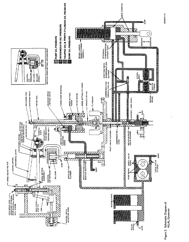
(2) Key components and mechanisms
Core components: oil pump, pressure storage area, relief valve, flyweight head directional valve assembly, power cylinder, compensation system, pneumatic speed control mechanism
Speed regulation mechanism
Direct speed regulation: control the increase of air pressure → increase of speed (minimum 3 psi, maximum 100 psi)
Reverse speed regulation: control the increase of air pressure → decrease of speed
Manual speed regulation: When there is no air pressure signal, adjust it within the normal speed range through the knob
Response to special working conditions
Temperature compensation: The old model uses bimetallic strips, while the new model is integrated into the speed regulating spring
Signal loss: Direct speed regulator reduces to minimum speed, reverse speed increases to maximum speed
Maintenance and upkeep
(1) Troubleshooting steps
Confirm if the load exceeds the capacity of the prime mover
Check the working status of the prime mover (engine cylinder ignition, turbine steam valve, etc.)
Check if the connecting rod is stuck or has empty travel
Check for changes in steam/fuel pressure
Verify the compensation needle valve setting and the output pressure of the pneumatic transmitter
Detect the working oil pressure of the governor (standard 100 psi)
(2) Disassembly and assembly
Dismantling sequence: Operate according to the index numbers in Figure 5-1 and 5-2, discard old gaskets, O-rings, etc
Cleaning requirements: Use compatible solvents for ultrasonic cleaning, blow dry with compressed air, and avoid scratching with metal brushes
Assembly specification: Operate in a dust-free environment, apply clean lubricating oil to moving parts, and tighten bolts to the specified torque (such as 45 lb ft for power cylinder bolts)
(3) Parts maintenance
Key inspection points: bearings (replace if there is roughness), flyweight (replace if worn), speed regulating springs (replace if corroded/damaged)
Replacement requirement: Information such as the serial number, part number, manual number, etc. of the speed controller must be provided
Auxiliary functions and membrane speed regulation
(1) Optional auxiliary device
Function and requirements of auxiliary devices
When the oil temperature of the governor oil cooler exceeds 93 ℃ or the speed exceeds 1200 rpm (engine)/1100 rpm (turbine), it is necessary to equip it
The shutdown device includes pneumatic/hydraulic/hydraulic type and electromagnetic type, and cannot be used as overspeed protection (independent overspeed device is required)
Pre loaded buffer spring reduces fuel linkage fluctuations caused by misfire or pump instability
Boost servo motor assists in quick engine start, immediately pushing the connecting rod to the fuel on position
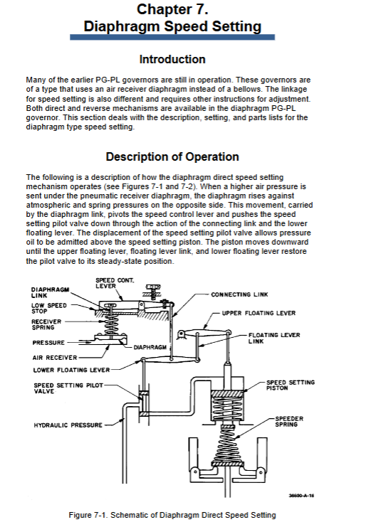
(2) Diaphragm speed regulation setting
Applicable scenario: Early PG-PL speed controller (using air receiver diaphragm instead of bellows)
Adjustment logic: Set the correspondence between air pressure and speed through sliding blocks, idle screws, and base speed adjustment nuts. The direct and reverse types require adjustment of the connecting rod arrangement
- YOKOGAWA
- Reliance
- ADVANCED
- SEW
- ProSoft
- WATLOW
- Kongsberg
- FANUC
- VSD
- DCS
- PLC
- man-machine
- Covid-19
- Energy and Gender
- Energy Access
- Renewable Integration
- Energy Subsidies
- Energy and Water
- Net zero emission
- Energy Security
- Critical Minerals
- A-B
- petroleum
- Mine scale
- Sewage treatment
- cement
- architecture
- Industrial information
- New energy
- Automobile market
- electricity
- Construction site
- HIMA
- ABB
- Rockwell
- Schneider Modicon
- Siemens
- xYCOM
- Yaskawa
- Woodward
- BOSCH Rexroth
- MOOG
- General Electric
- American NI
- Rolls-Royce
- CTI
- Honeywell
- EMERSON
- MAN
- GE
- TRICONEX
- Control Wave
- ALSTOM
- AMAT
- STUDER
- KONGSBERG
- MOTOROLA
- DANAHER MOTION
- Bentley
- Galil
- EATON
- MOLEX
- Triconex
- DEIF
- B&W
- ZYGO
- Aerotech
- DANFOSS
- KOLLMORGEN
- Beijer
- Endress+Hauser
- schneider
- Foxboro
- KB
- REXROTH
- YAMAHA
- Johnson
- Westinghouse
- WAGO
- TOSHIBA
- TEKTRONIX
- BENDER
- BMCM
- SMC
- HITACHI
- HIRSCHMANN
- XP POWER
- Baldor
- Meggitt
- SHINKAWA
- Other Brands
- UniOP
- KUKA
- IBA
- Beckhoff
- ADLINK
-
Beckhoff KL3162 - PLC Module KL 3162
-
Beckhoff EL3255 - PLC module
-
Beckhoff AX5201-0000 - servo driver
-
Beckhoff CX5130-0125 - Embedded PC Intel Atom 1.75GHz processor, 4GB DDR3 RAM
-
Beckhoff CU1521 - industrial switch
-
Beckhoff C6920-1057-0030 - #NAME?
-
B&R 7CP476.60-1 - 1 module 1
-
Beckhoff KL2552 - PLC module
-
Beckhoff CP6223-0002-0060 - #NAME?
-
Unknown BK7350-1060 - EtherCAT bus coupler
-
Beckhoff CX2040-0155 - Automation Basic CPU module, Windows 10 IoT Enterprise
-
Beckhoff CX5230-0175 - 000029724 Embedded PC Industrial PC On Rail
-
Beckhoff EL4134 - PLC Modules
-
Beckhoff EK1100 - automation coupling module EtherCat coupler coupling modules
-
Beckhoff EL6201 - Programmable Controller Module
-
Beckhoff CX2033-0175 - 000107116 embedded PC
-
Beckhoff AM3021-0C40-0000 - #NAME?
-
Beckhoff CX1020-0021 - CPU Module
-
Beckhoff CX2030 - PLC CPU Module
-
Beckhoff CX5130-0120 - PLC Modules
-
Beckhoff CX5230-0175 - 000029724 Embedded Controller Auf Schiene Industrial Pc
-
Beckhoff CX5130-0175 - PC CPU Module HW 4.4 Intel Atom Industrial CX2900 0038 40GB
-
Beckhoff AX5125-0000-0200 - #NAME?
-
Beckhoff KL3011 - One PLC Module
-
Beckhoff CX2020-0120 - 4 GB Basic CPU Module
-
Beckhoff CX1100-0920 - PLC CPU Module Module
-
AB 20F11NC3P5JA0NNNNN - Industrial Automation Part
-
Beckhoff AX5206-0000-0200 - #NAME?
-
Beckhoff CP6700-0001-0050 - , -
-
Beckhoff BECKHOFF-FOR-CX2000-4GB-CFAST-CARD-SLC-FLASH - - - -
-
B&R X67BC6321.L12 - X67 SYSTEM
-
Beckhoff CX9000-0001 - Controller module
-
Beckhoff AX5206-0000-0200 - #NAME?
-
Beckhoff CP2919-0000 - Multitouch Built In Control Panel 24VDC 19"
-
Beckhoff CP6032-0000-0010 - - 15" OPERATOR CONTROL PANEL
-
Beckhoff KL2791 - PLC module
-
Beckhoff CP7902-0001-0000 - - Touch Panel Power Supply 24VDC
-
Beckhoff CP6702-0001 - Open Interface Panels
-
Beckhoff CU8800-0010 - Communication / Interface Module Module
-
Beckhoff C6920-0010 - Driver
-
Beckhoff EL6614 - EtherCAT / Bus Terminal
-
Beckhoff AX5203-0000-0200 - #NAME?
-
Beckhoff EK1322 - 2 port EtherCATP junction Rev 0017
-
Beckhoff EP2349-0021-16 - EtherCAT Box - 16 Channel Module
-
Beckhoff CP6801-0021-0010 - Touch Panel - 12" 14 1 1020
-
Beckhoff CX1020-0112 - - N00 N010 CX1100 0004 PLC CONTROLLER R1S13.7
-
Beckhoff EL2784 - EtherCAT / Bus Terminal Module
-
Beckhoff CX2020-0155 - PLC CPU Module Module
-
Beckhoff EK1914 - PLC EK 1914 Module
-
Beckhoff Cx5130-0122 - PLC CPU Module
-
Beckhoff CX5010-0112 - CPU module
-
Beckhoff CP7811-0001 - - 0 0
-
Beckhoff EL3162 - controller module
-
Beckhoff CU2508-0000 - 8 Port Port Multiplier PLC Processor
-
Beckhoff CX5010-1112 - Mod CPU Module K Bus Windows Runtime TwinCAT 2 NC
-
Beckhoff BECKHOFF-CX2100-0914-CX21000914 - Industrial Automation Part
-
Beckhoff CX1500-M310 - PLC Module
-
B&R 7CP476.60-1 - 1 module 1
-
Beckhoff EL5042 - EtherCAT / Bus Terminal
-
B&R AT6402 - X20 PLC MODULE X20 ORIGINAL
-
Beckhoff CP7802-1327-0010 - #NAME?
-
Beckhoff CX1100-0002 - Power Module
-
Beckhoff CX2040-0155 - PLC CPU Module
-
Beckhoff EP1809-0021 - PLC Modules
-
Beckhoff CX2040 - 0142 Communication Module
-
Beckhoff CX2900-0033 - PLC CPU Module
-
Beckhoff CX2500-0030 - Interface Module
-
Beckhoff EK1100 - Module Ethernet Kommunikaton Modul
-
Beckhoff KL4428 - Bus Terminal 8 Channel Analog Output
-
Beckhoff CX5130-0122 - embedded PC CPU module 4 GB industrial PC CPU module HW 3.5
-
Beckhoff CX9020-0111-1002 - PLC CPU Module
-
Beckhoff CP6929-0001-0000 - Touchscreen Panel 6.5" ELO Model -
-
Beckhoff EP4174-0002 - Module HTP0
-
Beckhoff CP6092-0011-0000 - - Touch Screen 15" Panel
-
B&R 5WCC00000440K0-001 - PANEL PC 2100 SYSTEM UNIT AUTOMATION PANEL
-
Beckhoff CX2100-0014 - Original
-
Beckhoff CX5120-0115 - 3243
-
Beckhoff CP3919-1039-0011 - Multi Touch Control Panel - 19" G190ETN01.2
-
Beckhoff CX9001-0101 - PLC Module QW
-
Beckhoff BECKHOFF-CX5120-121 - Industrial Automation Part
-
Beckhoff BECKHOFF-BX8000-0000 - Industrial Automation Part
-
Beckhoff AX511200000200 - AX5112 0000 0200 Servo Driver
-
Beckhoff EL2564 - EtherCAT Terminal, 4 channel LED output, 5 8VDC, 4A, RGBW
-
Beckhoff KL4494 - EtherCAT / Bus Terminal
-
B&R 5e9000.17 - Control Panel
-
Beckhoff BX8000 - PLC Module
-
Beckhoff AS1060-0110 - , Stepper Motor Precision .........
-
B&R 0702-10B - 6PPT50. Touch Panel
-
Beckhoff C6930-0050 - Schaltschrank Industrie Pc Core i7 4700 CPU+FC9062 Module
-
Beckhoff KL2702 - PLC Controller Module
-
Beckhoff EL4038 - Communication Module
-
Beckhoff EK1110-0008 - EtherCAT / Bus Terminal Module
-
Beckhoff CX5020-0111 - PLC CPU Module
-
Beckhoff CP7232-0001-0050 - #NAME?
-
Beckhoff FC3101-0000 - communication module
-
Beckhoff EL6930 - EtherCAT Klemme
-
Beckhoff EL6631 - EtherCAT / Bus Terminal
-
Beckhoff EK1100 - ,EL2202,EL1904,EL1809,EL9189,EL9188,EL2809,EL3122,EL3102,EL4102
-
Beckhoff EL6695 - EtherCAT / Bus Terminal
-
Beckhoff CX1500-M510 - CX1020 N000 CX1020 0011 CX1100 0002 Controller Set
-
Beckhoff AM8052-1F20-0000 - - motor -
-
Beckhoff C6925-1004 - Industrial PC
-
Beckhoff 7132-0001 - CPPC
-
Beckhoff CP6001-0011-0010 - - Control Panel 12 inch TFT Display, 001...
-
Beckhoff CX2020-0120 - 4GB CPU ,CX2100 0904 3x EL6900, EL1904 16 GB Memory
-
Beckhoff C6920-0030 - Controller
-
B&R 3DM486.6 - DIGITAL MIXED MODULE DM486
-
Beckhoff KL3361 - PLC Module KL 3361
-
Beckhoff C9900-H391 - operating system
-
Unknown CKS-10T - Industrial Automation Part
-
Beckhoff AX5206-0000 - server Driver
-
Beckhoff CP6800-0001-000 - #NAME?
-
Beckhoff CX1100-0920 - Module 24VDC Controller Module
-
Schneider 140CRP31200 - IPC PLC Module In Box
-
Beckhoff C6930-1001 - Industrial PC
-
Beckhoff FC9002 - FC 9002 Ethernet PCI Network Card
-
Beckhoff EL6070-1296 - license key terminal EtherCAT
-
Beckhoff CP7721-1036-0010 - Display Control Panel
-
Beckhoff FC3101 - 2022 Module
-
Beckhoff EK9300-1007 - EtherCAT / Bus Terminal Module
-
Beckhoff AX8640-0000-0000 - #NAME?
-
Beckhoff CP7932-0001-0000 - - touch screen -
-
Beckhoff CX5020-0110 - HW Version 3.4 CPU Module
-
Beckhoff CP2912-0000 - touch screen in box
-
Beckhoff AX5118-0000-0200 - #NAME?
-
B&R 2EX302.5 - Extension unit EX302
-
Beckhoff CX5140-0111 - 1884
-
Beckhoff EQ8003-2042 - Ethercat I o Module

K-JIANG

Add: Jimei North Road, Jimei District, Xiamen, Fujian, China
Tell:+86-15305925923