
K-WANG


Foxboro Evo ™ Standard 200 Series Baseplates(PSS 31H-2SBASPLT)
Module carrying and positioning: providing standardized slots for adaptation Field Control Processor(FCP)、Field Device Controller(FDC)、Field Communications Module(FCM)、Fieldbus Module(FBM) Waiting for multiple types of modules to achieve modular layout;
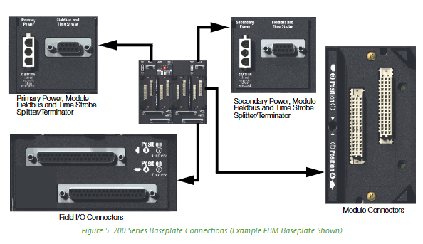
Signal and power distribution: Built in 2 Mbps HDLC redundant serial bus (Module Fieldbus), responsible for data exchange between modules; Simultaneously provide 24V DC redundant power interface to provide stable power supply for all mounted modules;
Redundancy and Scalability Support: Compatible with module level redundancy (such as FCP/FDC redundancy pairs), and supports online addition of substrates (requiring redundant buses) to meet system expansion requirements;
Compatibility Connection: Downward compatible with 100 Series FBM (requiring 268 Kbps fieldbus), upward compatible with Foxboro Evo control network, achieving smooth transition between old and new systems.
Foxboro Evo ™ Standard 200 Series Baseplates(PSS 31H-2SBASPLT)
Core positioning and subsystem roles
The standard 200 series substrate is Foxboro Evo ™ The core functions of the "hardware connection center" of the system include:
Module carrying and positioning: providing standardized slots for adaptation Field Control Processor(FCP)、Field Device Controller(FDC)、Field Communications Module(FCM)、Fieldbus Module(FBM) Waiting for multiple types of modules to achieve modular layout;
Signal and power distribution: Built in 2 Mbps HDLC redundant serial bus (Module Fieldbus), responsible for data exchange between modules; Simultaneously provide 24V DC redundant power interface to provide stable power supply for all mounted modules;
Redundancy and Scalability Support: Compatible with module level redundancy (such as FCP/FDC redundancy pairs), and supports online addition of substrates (requiring redundant buses) to meet system expansion requirements;
Compatibility Connection: Downward compatible with 100 Series FBM (requiring 268 Kbps fieldbus), upward compatible with Foxboro Evo control network, achieving smooth transition between old and new systems.
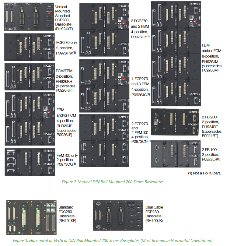
Classification and core functions of substrates
According to the number of slots (2/4/8), installation direction (horizontal/vertical), and supported module types, Standard 200 series substrates can be divided into multiple categories. The core functions and adaptation scenarios of each category are shown in the table below:
Substrate type, slot number, installation direction, support module/core function, typical model/substitution relationship, adaptation scenario
FCP280 dedicated substrate 2 horizontal/vertical - single module or redundant for FCP280;
-Supports 4 HDLC fieldbus ports (port 1 can be terminated through DIP switch, ports 2-4 have built-in termination);
-Optional dual cable version (independent A/B bus interface+time synchronization input) RH924YL (standard), RH100JX (dual cable);
Replacing the old CP60 related substrate requires high reliability control for medium to large-scale systems (such as chemical and electrical)
FDC280 dedicated substrate 2 vertical (horizontal orientation needs to be maintained) - single module or redundant pair FDC280;
-Support Ethernet/serial interface (for connecting field devices);
-Horizontal DIN rail installation is required to meet the classification certification RH101KF (unique model) for scenarios where FBM is not needed to directly connect on-site equipment (such as small control units)
FCP270 dedicated substrate 2 horizontal/vertical - single module or redundant for FCP270;
-Reserve installation space for fiber optic splitters/combiners;
-Hardwired address (substrate 0, no ID dialing) P0926HC (horizontal), P0926HW (vertical);
Non RoHS component small and medium-sized system upgrade (replacing old controllers)
FEM100 dedicated substrate 2 vertical - redundant pair for FEM100;
-Expand the number of FBMs supported by FCP270 (up to 4 expansion fieldbuses, each supporting 32 200 Series FBMs) P0973CG (non RoHS), RH924RT (replaces old model) FCP270 system I/O expansion
FBI specific substrate 2 vertical - FBI200/FBI100 redundant pair;
-FBI200 substrate with baud rate selection DIP switch;
-No need for hard wired address (no ID dialing) P0923LR (FBI100, non RoHS), RH924RT (FBI200) fieldbus isolation/filtering (anti-interference requirement scenario)
FCM/FBM universal substrate 2/4/8 horizontal/vertical -2 bits: single module/redundant pair FCM, or 2 FBMs (hard wired address 0, no ID dip code);
-4/8 bits: 4/8 FBMs or 2 FCMs+2 FBMs (including ID dialing, supporting substrate grouping) 2 bits: RH926KE (horizontal), RH926KH (vertical);
4-digit: RH926HM (replacing P0926HM);
8-bit: RH926HT (replacing P0926HT) pure I/O expansion or FCM+FBM combination scenario
FCP270+FEM100 hybrid substrate 4 vertical -2 redundant FCP270+2 redundant FEM100;
-No ID dialing, relying on FCP270 expansion port management P0973CN (non RoHS) FCP270 system for large-scale I/O expansion (such as multi device clusters)
FCP270+FBM hybrid substrate 4 horizontal/vertical -2 redundant FCP270+2 FBM (including ID dialing);
-Or 1 FCP270+3 FBM (non redundant) P0926HJ (1 FCP270+3 FBM), P0926HF (2 FCP270+2 FBM);
Non RoHS component small system (control+I/O integration, no redundancy requirements)
Key technical characteristics
(1) Module identification and address configuration
The substrate implements the mapping between modules and system software through the * * "Letterbug" string * * (6 bits), and the Letterbug generation rules for different modules are different:
FBM (with FCM): composed of "FCM's first 4 Letterbug+substrate ID (dial setting)+module physical position (1-8)";
FBM (with FCP280/FCP270): composed of "custom first 4 digits (not duplicated with FCP)+substrate ID (non FCP280 substrate dialing)+module position+FCP expansion port number (hexadecimal for FEM100 scenario)";
FCP280/FDC280: Set "Soft Letterbug" through the module panel buttons;
FCP270/FCM100E: Set "Soft Letterbug" through the I/A Series Letterbug configuration tool.
(2) Redundancy and scalability
Module redundancy rules:
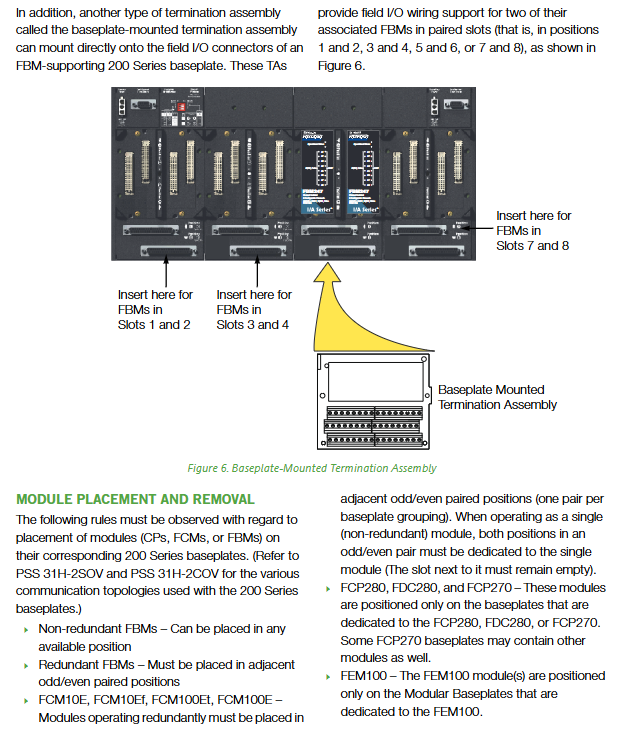
Redundant FBM/FCM should be installed in adjacent odd/even slot pairs (such as positions 1-2 and 3-4);
Non redundant FCM needs to occupy a pair of slots (adjacent slots are vacant);
FCP/FDC/FEM/FBI redundancy requires the use of a dedicated 2-digit substrate.
Online Expansion:
The system needs to have A/B redundant buses and split the bus signals through a "fieldbus splitter/terminator" (such as RH926KW);
When adding a new substrate, there is no need to interrupt the system operation, only the redundant cables need to be connected to the power supply.
(3) Signal and Communication Specifications
Specification category parameter details
Fieldbus type -200 Series module: 2 Mbps HDLC redundant serial bus (shielded twisted pair);
-100 Series module: 268 Kbps bus (dual axis cable)
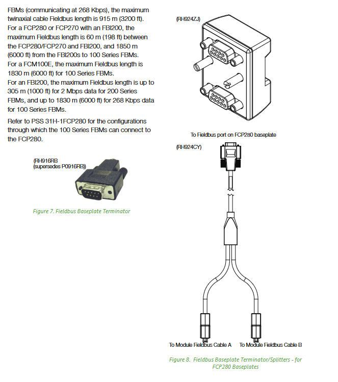
Maximum communication distance -200 Series FBM (FBI200): 305 m (2 Mbps);
- 100 Series FBM(FBI200):1830 m(268 Kbps);
-FCP280 directly connected to 100 Series FBM: 915 meters
Time synchronization supports optional GPS time synchronization input (requires splitter/terminator, such as RH924ZQ(FCP280)、RH926KZ(FCM100E/FCP270))
The bus cable between signal isolation substrates is shielded twisted pair to reduce electromagnetic interference (EMI)
Detailed explanation of technical specifications
(1) Electrical and Environmental Specifications
Specification category parameter details
Power requirements - Input voltage: 24 V DC (redundant);
-Cable length: 0.4 m (16 inches) to 2.1 m (7 feet)
Environmental adaptability (working) - Temperature: -20~+60 ° C (-4~+140 ° F);
-Humidity: 5% to 95% (without condensation);
-Altitude: -300 to+3000 meters;
-Pollution level: G3 level (harsh environment, compliant with ISA S71.04)
Environmental adaptability (storage) - Temperature: -40~+70 ° C (-40~+158 ° F);
-Altitude: -300 to+12000 meters
Compliance Certification - EMC: Compliant with EN61326:2013 Class A emission/industrial immunity (EU Directive 2014/30/EU);
-Safety: UL/UL-C Class I Div 2 (Groups A-D, T4)、ATEX Ex nA IIC T4 Gc;
-Classification: ABS/French BV certification (EC31, except for some models);
-Environmental Protection: Compliant with RoHS 2011/65/EU (non RoHS model labeling)
(2) Physical and installation specifications
Specification category parameter details
Installation method - DIN rail: compatible with horizontal/vertical installation (keeping the substrate in a horizontal position);
-Cabinet installation: 19 inch rack (requires P0930AS installation kit, depth 25.4mm)
Weight (excluding modules) -2-position substrate: approximately 0.5 kg (1.1 lb);
-8-bit substrate: maximum 0.91 kg (2.0 lb)
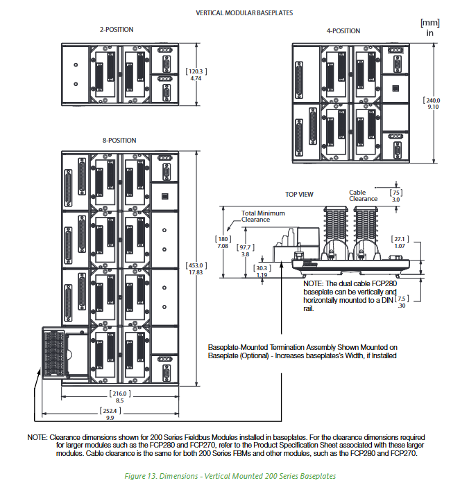
Key dimensions (example) -2-digit vertical substrate: height 120.3 mm, width 240.0 mm;
-8-bit horizontal substrate: length 453.0 mm, height 216.0 mm (including optional terminal components)
Materials and Protection - Shell: PC+ABS (UL94 V0 flame retardant);
-Rail fasteners: made of steel (quantity varies with substrate size);
-Color: Black
Key points for installation and maintenance
(1) Module installation rules
Redundant module layout:
Redundant FBM/FCM needs to occupy adjacent odd/even slot pairs (such as 1-2, 3-4 bits);
FCP/FDC/FEM/FBI redundancy requires the use of a dedicated 2-position substrate and cannot be mixed with other modules.
Non redundant module limitation:
Non redundant FCM needs to occupy a pair of slots (adjacent slots are vacant);
FBM can be installed in any vacant slot (matching substrate support type).
(2) Key accessories and connections
Accessory type, function, typical model
Fieldbus splitter/terminator - Termination bus signal: RH916RB (replacing P0916RB);
-Split A/B bus+time synchronization: RH926KW (non FCP280), RH924ZJ (FCP280 port 1);
-Connect 100 Series FBM: RH926LC (replacing P0926LC) RH916RB, RH926KW, RH928CV (FCP280 extension)
Connect the power cable between the FPS series power supply (such as FPS480-24) and the substrate:
- RH100DZ(0.6 m)、RH100EA(1.0 m) RH100DZ、RH100EA、RH100EB(2.1 m)
Substrate installation kit 19 inch rack installation: including bracket and fasteners P0930AS
(3) Maintain convenience
Hot swappable support: FCP, FEM, FCM, FBI, FBM can all be plugged and unplugged online without disconnecting field cables, power supplies, or communication buses;
Fault diagnosis: Clearly labeled connector functions (power/fieldbus/I/O) on the substrate, combined with module LED indicator lights (such as power and communication status), can quickly locate faults;
Online expansion: Under the redundant bus architecture, when adding FBM support substrates, only A/B bus splitters need to be connected without shutting down.
Related reference documents and support
Document type Document number/name Core purpose
Subsystem Overview PSS 31H-2SOV (Standard 200 Series), PSS 31H-2COV (Compact 200 Series) System Architecture and Substrate Matching Rules
Module specifications PSS 31H-1FCP280 (FCP280), PSS 31H-2FDC280 (FDC280) module and substrate adaptation details
User Guide B0400FA (Standard and Compact 200 Series Subsystem User's Guide) Installation, Wiring, and Troubleshooting Steps
Substrate configuration for hazardous area applications of PSS 31H-2Y12 (ISTA-BP Intrinsic Safety Terminal Substrate) related to intrinsic safety
- YOKOGAWA
- Reliance
- ADVANCED
- SEW
- ProSoft
- WATLOW
- Kongsberg
- FANUC
- VSD
- DCS
- PLC
- man-machine
- Covid-19
- Energy and Gender
- Energy Access
- Renewable Integration
- Energy Subsidies
- Energy and Water
- Net zero emission
- Energy Security
- Critical Minerals
- A-B
- petroleum
- Mine scale
- Sewage treatment
- cement
- architecture
- Industrial information
- New energy
- Automobile market
- electricity
- Construction site
- HIMA
- ABB
- Rockwell
- Schneider Modicon
- Siemens
- xYCOM
- Yaskawa
- Woodward
- BOSCH Rexroth
- MOOG
- General Electric
- American NI
- Rolls-Royce
- CTI
- Honeywell
- EMERSON
- MAN
- GE
- TRICONEX
- Control Wave
- ALSTOM
- AMAT
- STUDER
- KONGSBERG
- MOTOROLA
- DANAHER MOTION
- Bentley
- Galil
- EATON
- MOLEX
- Triconex
- DEIF
- B&W
- ZYGO
- Aerotech
- DANFOSS
- KOLLMORGEN
- Beijer
- Endress+Hauser
- schneider
- Foxboro
- KB
- REXROTH
- YAMAHA
- Johnson
- Westinghouse
- WAGO
- TOSHIBA
- TEKTRONIX
- BENDER
- BMCM
- SMC
- HITACHI
- HIRSCHMANN
- XP POWER
- Baldor
- Meggitt
- SHINKAWA
- Other Brands
- UniOP
- KUKA
- IBA
- Beckhoff
- ADLINK
-
ADLINK HPCI-14S12U - Industrial Control Backplane 12PCI Backplane PCI-14S Passive Backplane
-
ADLINK PCIe-GIE74C - image acquisition card 4-CH GigE Vision PoE+ Frame Grabber
-
ADLINK PCI-8164 - control card 4-Axis Advanced Motion Controller Board
-
ADLINK PCIe-U304 - 4 Port USB3 PCIe Frame Grabbers USB Screw Hole Card
-
ADLINK PCI-9112 - Multi-Function Data Acquisition Card DAQ Card
-
ADLINK PCI-7432 - 51-12013-0A50 4-CH Isolated Numérique I/O PCI Cartes Digital I/O Card
-
ADLINK PCA-6106P3-0C1 REV.C1 - backplane 6-Slot Passive Backplane Board
-
ADLINK PCI-7224 - 24-CH Opto-Isolated Digital I/O PCI Board
-
ADLINK CPCI-7433R(G) - Digital Input Board Rear I/O CompactPCI Card
-
ADLINK EBP-13E4 - 51-46703-0A30 Industrial PC Backplane Passive Backplane
-
ADLINK PCIE-HDV62 - Image acquisition card High Definition Video Frame Grabber
-
ADLINK EBP-13E4 - 51-46703-0A30 Industrial Backplane Board Passive Backplane
-
ADLINK 90111-B1 / CPCI-6770 - PCB CPU MODULE CompactPCI Single Board Computer
-
ADLINK PCI-7248 - DATA ACQUISITION PCI CARD 48-CH Parallel Digital I/O Board
-
ADLINK PCI-7230 - 51-12003-0a50 board PCI7230 32-CH Isolated Digital I/O Card
-
ADLINK PCI2A000CB - 51-20000-0B30 Multi-Function DAQ Card Baseboard
-
ADLINK PCI-8134-005 - 4-Axis Motion Controller Card
-
ADLINK PCI-7224 - 24-CH Opto-Isolated Digital I/O PCI Card
-
ADLINK PCI-7434 - 64-CH Isolated Digital Output Card
-
ADLINK PCI-8132 - motion control card 2-Axis Servo & Stepper Controller
-
ADLINK PCI-8134 - Motion Controller PCI Card 4-Axis Controller Board
-
ADLINK PCI-8164 - Motion Control Card 51-12406-0A40 4-Axis Controller
-
ADLINK 51-12001-0C20 - Circuit Board Data Acquisition Interface Module Hardware
-
ADLINK NuPR0-840 - industrial control motherboard Full-Size PICMG CPU Board
-
ADLINK PCI-7444 - 51-12023-0A10 card 128-CH Isolated Digital Output Board
-
ADLINK PCI-1612B - data acquisition card 4-Port RS-232/422/485 Serial Communication Card
-
ADLINK PCI-6208V 009 - 8/16-CH 16-Bit Analog Output Cards PCB-I-E-482=6BX3
-
ADLINK NUPRO-935A/LV - industrial control motherboard Full-Size PICMG SBC Board
-
ADLINK PCI-9114DG - Multi-Function DAQ Card Data Acquisition PCI Card
-
ADLINK ACL-7130 - Data acquisition card Isolated Digital I/O Board
-
ADLINK ABX-6300D-4E1-BP - board ABX6300D4E1BP Video Interface Expansion Card
-
ADLINK CPCI-6940 - CPCI-6940/D1539/M16-0(EA)-000E 6U CompactPCI Processor Board
-
ADLINK NuPRO-760 - industrial control motherboard Half-Size PICMG SBC CPU Board
-
ADLINK IMB-M42H (G)-0020 - industrial control motherboard LGA1155 Micro-ATX Mainboard
-
ADLINK RTV-24 / PCI-MP4S - 51-12519-1C30 4-Channel Real Time Video Capture Board
-
ADLINK PCI-8134 - 4-Axis Servo & Stepper Motion Controller Card
-
ADLINK MXC-6101D - V.PC000.002.ST.00 Box PC Configurable Embedded Computer
-
ADLINK PCI-8134A - 51-12421-0A10 Motion Control Card 4-Axis Controller Card
-
ADLINK DIN-100S / DIN-100SA1 - Technology SCSI-II TB 100-PIN Terminal Block Board
-
ADLINK DIN-812M001 / DIN812M001 - 51-14034-0A1 51140340A1 Terminal Module Breakout Interface
-
ADLINK PCI-8164 - Servo motion control 4-Axis Advanced Controller Card
-
ADLINK PCIe-GIE64 - Acquisition card GigE Vision PoE+ Frame Grabber
-
ADLINK M-302 - Industrial control motherboard ATX PC Board Mainboard
-
ADLINK PCI-8134 - Motion Controller PCI Card 4-Axis Controller Board
-
ADLINK PCI-RTV24 - Image capture card Analog Video Frame Grabber
-
ADLINK PCI-8102 - Motion control card 2-Axis Servo & Stepper Controller Board
-
ADLINK PCI-9112 REV.B1 - Card Multi-Function Data Acquisition Card
-
ADLINK HSI-DI32-M-N / HSL-TB32-M-DIN - Discrete I/O MODULE Distributed Automation Module System
-
ADLINK PCI-7296 - IO card REV.A3 96-CH Parallel Digital I/O Card
-
ADLINK DIN-814P-A4 / 814Y - terminal board Motion Control Interface Block
-
ADLINK DIN-814P-A4 - 51-14056-0A10 PCB-I-E-2736=ZA01 Screw Terminal Board Breakout
-
ADLINK M-322 - motherboard Industrial Control Computer Mainboard
-
ADLINK NUPRO-406 REV:B1 - industrial control motherboard Full-Size PICMG CPU Board
-
ADLINK AMP-204C - card DSP-Based 4-Axis Advanced Pulse-Train Controller
-
ADLINK HPCI14S REV.B1 - industrial computer baseboard 14-Slot Passive Backplane
-
ADLINK PCI-7250 - 8-CH Relay Output & 8-CH Isolated DI PCI Card
-
ADLINK EBP-13E2 - baseplate Passive Backplane Industrial Computer Chassis Board
-
ADLINK LPCI-3488A - PCI-GPIB card 51-12801-0A30 acquisition card IEEE-488 Interface Board
-
ADLINK PCI-6216V-GL - 51-12201-0C30 16-CH 16-Bit Voltage Analog Output Card
-
ADLINK ACL-8454 - 16-CH Isolated Digital I/O & 4-CH Counter Card
-
ADLINK HPCI-9S7U - backplane Passive Backplane Compatible with NuPRO-A301 852 841 842
-
ADLINK DAQ-2010-007 - Simultaneous-Sampling Multi-Function Data Acquisition Card
-
ADLINK MP-C154 - 51-64205-0A10 Motion Control Card 4-Axis Controller Board
-
ADLINK MXE-202/mSSD16B/WiFi-BT - Matrix Rugged I/O Platform Embedded Fanless Computer
-
ADLINK CM-920-R-17 - PC/104-Plus Single Board Computer Module Intel Celeron M
-
ADLINK PCI-7250 NSMP - 8-CH Relay Output & 8-CH Isolated DI Card
-
ADLINK PCI-8164 - 4-Axis Motion Controller PCI Card W/ Cable and Breakout Box
-
ADLINK EMX-100 - Ethernet-based 4-axis Motion Controllers Distributed Motion Module
-
ADLINK PCI-8134A - Press control card 4-Axis Motion Controller Board
-
ADLINK M-845EG REV:3.2 - industrial motherboard Pentium 4 Socket 478 Micro-ATX
-
ADLINK PCI-9114A Rev A2 DG - card High-Resolution Multi-Function Data Acquisition Board
-
ADLINK IEC-915GV - REV 1.1 Industrial motherboard Socket 478 CPU Board
-
ADLINK PCI-9111DG(G) - Data Acquisition Card Multi-Function DAQ Card
-
ADLINK HPCI-15S10 REV:B2 - Industrial computer base plate Passive Backplane Board
-
ADLINK NuPR0-840 / NuPR0-840DV - industrial control motherboard Full-size PICMG CPU Board
-
ADLINK RTV-24 / PCI-MP4S - 51-12519-1C30 4-Channel Real Time Video Capture Board
-
ADLINK NUPRO-780 - industrial control motherboard Pentium III Single Board Computer
-
ADLINK PCI-7296 - 0050 card 96-CH Opto-Isolated Parallel DIO Card Set
-
ADLINK NUPRO-780 - industrial control motherboard PICMG Full-Size SBC
-
ADLINK PCI-7248 - 51-12006-0A3 002 Pci 7248 48-CH Parallel Digital I/O Card
-
ADLINK cPCI-6626 - 6U CompactPCI 2.0 Blades i7-2710QE PCB-I-E-2570=9N41
-
ADLINK MXC-6322D(G) - Industrial Fanless Computer
-
ADLINK cPCI-8168-004 - CompactPci NulPC Motion Control Board 51-36402-0A3
-
ADLINK CPCI-7300[G] - COMPACTPCI Digital I/O Card Data Acquisition
-
ADLINK CPCI-6626/2710/M4G - COMPACTPCI COMPUTER BOARD
-
ADLINK cPCI-8168-009 - cPCI NulPC Motion Control Board
-
ADLINK cPCI-6626/2710/M4G - VME CPU Board Computer Board
-
ADLINK CPCI-R6200(G)-0040 - COMPACTPCI CONTROL BOARD
-
ADLINK CPCI-3840/PM18/M1G(G)-3650 - COMPACTPCI CPU Module Single Board Computer
-
ADLINK cPCI-7248 - 48-CH Opto-22 Compatible Digital I/O Module
-
ADLINK DLAP-211-JNX - NVIDIA Jetson Xavier NX Edge AI Inference Platform
-
ADLINK cPCI-3544 - Series 4-Port RS-422/485 Isolated Serial Communications Card
-
ADLINK CM1-86DX3 - PC/104 SBC Stanley Vortex86DX3 CPU 2GB Ram
-
ADLINK DLAP-211-JNX - NVIDIA Jetson Xavier NX Edge AI Inference Platform
-
ADLINK cPCI-3544 - Series 4-Port RS-422/485 Isolated Serial Communications Card
-
ADLINK CM1-86DX3 - PC/104 SBC Stanley Vortex86DX3 CPU 2GB Ram
-
ADLINK PCI-7433 - switch value acquisition card Isolated Digital Input Card
-
ADLINK PCI-9112 - 51-12252-0D20 Multi-Function Data Acquisition Card
-
ADLINK NUPRO-A301 REV:1.4 - industrial control motherboard PICMG Full-Size SBC
-
ADLINK 51-18502-0A10 - Frame Grabber Image Acquisition Interface Card
-
ADLINK PCI-7296 - 51-12009-0A50 PCB-I-E-925=6DX1 96-CH Parallel Digital I/O Board
-
ADLINK PCI-8132 GP A2 - Motion Control Card 2-Axis Servo & Stepper Controller
-
ADLINK PCI-7442 - switch quantity card data acquisition card 64-CH Isolated Card
-
ADLINK HPX-13S4 - baseboard PICMG 1.3 Passive Backplane Chassis Baseplate
-
ADLINK NuPRO-590 / NTC-567-ZM-F36 - Single Board Computer PCB-I-E-1853=9L21 Half-Size SBC
-
ADLINK PCIe-8332 - 16-axis plate Motion Control Hardware Card
-
ADLINK NuPRO-775 REV.B1 - motherboard Pentium 4 Full-Size PICMG SBC
-
ADLINK PXI-3920 - Embedded Controller 3U PXI cPCI System Intelligence Board
-
ADLINK PCI-8134 - driver card motion control card 4-Axis Controller Board
-
ADLINK HSL-DI32-M-N-011 / HSL-TB32-M-DIN - Digital Input & Base Module PLC Distributed I/O System
-
ADLINK PCI-6216V-206 / PCI-208V 009 - 16 CH 16bit analog output card
-
ADLINK NuPro-E330 - 51-41805-0A20 PCB Single Board Computer Host Board
-
ADLINK PCI-1622C - Card 8-Port RS-232/422/485 PCI Serial Communication Board
-
ADLINK PCIe-7432 - 51-18402-0A10 Carte PCIe Avec Plage D'Entrée Élevée Isolated DIO Card
-
ADLINK PCI-7250 - PCI Acquisition Card 8-CH Relay Output Isolated DI Card
-
ADLINK PCI-7230 - 32-CH Isolated Digital I/O Card
-
ADLINK PCI-8164 - PCB 4-Axis Motion Controller Card
-
ADLINK PCI-7854 - Collection card High-Speed Link Distributed Motion Controller
-
ADLINK NuPRO-935A/LV - industrial control computer motherboard Full-Size PICMG SBC
-
ADLINK IMB-M40H - motherboard IH61-AA4 1155 LGA1155 Micro-ATX Mainboard
-
ADLINK PCI-7248 - Linhua 51-12006-0A40 48-CH Parallel Digital I/O Card
-
ADLINK HPCI-14S12U - Linhua industrial computer baseboard Passive Backplane
-
ADLINK PCI-8132 Rev.A2 - 2-Axis Servo & Stepper Motion Controller Card
-
ADLINK ACL-8111 - ISA card Multi-Function DAQ Card
-
ADLINK ACL-8111 - ISA card Multi-Function Data Acquisition Board
-
ADLINK PCI-7200 REV.A3 - Digital I/O card 12MB/s High-Speed Parallel Digital I/O
-
ADLINK PCI-7296 REV.A3 - 96-CH High-Density Opto-Isolated DIO Card
-
ADLINK PCI-7434 - 64-CH Isolated Digital Output Card

K-JIANG

Add: Jimei North Road, Jimei District, Xiamen, Fujian, China
Tell:+86-15305925923