
K-WANG


BENDER RCMA475LY AC/DC sensitive residual current monitor
RCMA475LY AC/DC sensitive residual current monitor
Product Overview
RCMA475LY is an industrial grade AC/DC sensitive residual current monitor launched by BENDER in Germany, designed specifically for TN and TT systems (grounded power supply systems). Its core function is to monitor AC, DC, and pulsating DC currents in circuits, accurately identify DC fault currents or residual currents that are continuously greater than zero, and prevent safety risks such as electrical fires and electric shocks. Its unique Type B working characteristics make it particularly suitable for scenarios containing six pulse rectifiers, unidirectional rectification filtering loads, such as frequency converters, battery chargers, construction site variable frequency drive equipment, uninterruptible power supplies (UPS), etc. It is a key equipment for high reliability electrical safety monitoring in industrial production and civil buildings.
Core certification: Compliant with IEC/TR 60755 Type B standard, with EN 61543 and EN 61000-6-4 electromagnetic compatibility (EMC) certification, flame retardant rating of UL94V-0 for the shell, and protection level of IP30.
Core functions and features
(1) Monitoring and threshold control function
Dual level response threshold:
Alarm threshold (I Δ n1): 30... 500mA continuously adjustable, covering various monitoring requirements from low sensitivity to high sensitivity, with a frequency range of 0... 700Hz, suitable for the current characteristics of high-frequency rectifier loads.
Warning threshold (I Δ n2): Supports switching between two modes (set through DIP switch), with the option to select 50% or 100% of the alarm threshold, achieving a graded protection of "early warning+emergency alarm", making it easy for users to distinguish risk levels and handle them in a timely manner.
Adjustable response delay:
Alarm delay: 0... 10s infinitely adjustable, set through the potentiometer on the front panel, divided into two levels: x1 (0... 1s) and x10 (0... 10s), which can avoid false alarms (such as instantaneous current fluctuations during motor start-up) according to the on-site load characteristics.
Warning delay: 0s or 1s optional (DIP switch switching), quickly responding to potential risks while considering system stability.
Precision measurement mechanism:
Measurement core: Built in ø 18mm inner diameter measuring current transformer, using electromagnetic induction principle to monitor residual current, measurement results are almost unaffected by system load current and rated voltage, with strong stability.
Current type adaptation: It can accurately monitor 50Hz AC current, smooth DC current, positive and negative half wave pulsating DC current, phase controlled half wave current (delay angle 90 ° el/135 ° el), and half wave current with 6mA smooth DC superimposed, suitable for complex load scenarios.
(2) Operation and display functions
Multi functional operation button:
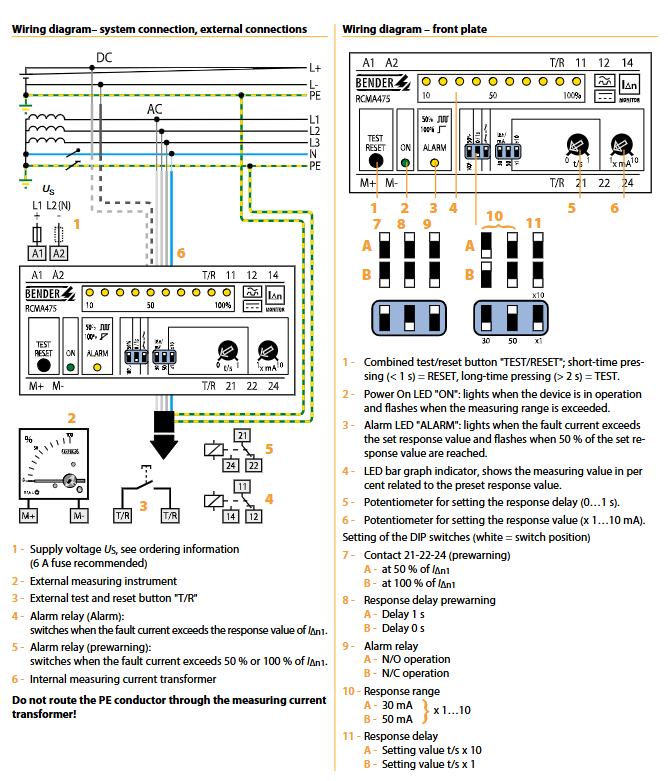
Built in combination "TEST/RESET" button: short press (<1s) for reset function, used to clear fault memory; Long press (>2s) is the testing function to verify whether the device monitoring and alarm circuit is working properly.
External Expansion: Supports connecting external test/reset buttons, with no hard limit on cable length, suitable for remote operation scenarios (such as operating outside the control cabinet).
Visual display system:
Power On LED: When the device is running normally, it stays on and flashes when the measured value exceeds the set range, providing quick feedback on the device's working status.
Alarm LED: It stays on when the alarm threshold is reached and flashes when the warning threshold is reached, visually distinguishing between warning and alarm states.
LED bar chart indicator: displays the proportion of measured residual current to the set threshold at a scale of 0... 100%, with a total of 10 levels. It visualizes the trend of current changes in real time, making it easy for on-site personnel to quickly determine the level of risk.
Fault memory function: The alarm status is automatically stored inside the device and will not be lost even if the power is cut off. It needs to be cleared through a reset operation for easy fault tracing and cause analysis.
(3) Output and extension functions
Dual independent alarm relay:
Configure 2 conversion contacts (1 normally closed+1 normally open), support N/O (normally open) or N/C (normally closed) operation mode switching (DIP switch setting), can link warning and alarm circuits separately (such as warning trigger indicator light, alarm cut-off main power supply), adapt to different control logic requirements.
Relay parameters: rated contact voltage 150V AC/DC, rated current 5A, making capacity 2A (AC 230V, cos φ=0.4), breaking capacity 0.2A (DC 220V, L/R=0.04s), electrical life up to 12000 cycles, high reliability.
External device expansion:
Support connecting external measuring instruments, the device provides 0... 400 µ A current source output (corresponding to 0... 100% residual current ratio), load resistance ≤ 12.5k Ω, and can be connected to industrial grade display instruments for centralized monitoring.
Transparent sealing cover design: The front panel is equipped with a sealable transparent cover to prevent misoperation or malicious tampering of parameters, suitable for installation needs in industrial sites and public areas.
Detailed technical parameters
(1) Electrical parameters
Insulation and voltage resistance:
Rated insulation voltage: AC 250V, in compliance with IEC 60664-1 insulation coordination standard.
Rated impulse withstand voltage: 4kV, pollution level 3, with strong resistance to power grid surges and interference.
Power supply specifications:
Supply voltage (by model): RCMA475LY(230V AC/DC)、RCMA475LY-13(90…132V AC/DC)、RCMA475LY-21(9.6…84V AC/DC)、RCMA475LY-23(77…286V AC/DC), The 230V model is suitable for industrial and civilian scenarios, while the other models are designed specifically for industrial applications and can be customized with other power supply voltage versions as needed.
Working range of power supply voltage: 0.85... 1.1 x rated power supply voltage, suitable for voltage fluctuations in the power grid.
Power supply frequency range: DC/50... 60Hz, universal AC/DC power supply, suitable for different power supply environments.
Equipment power consumption: ≤ 3.5VA, low-power design, reducing long-term operating costs.
Measurement accuracy and response characteristics:
Relative uncertainty of response value: ≤ 25%, small measurement error, high data reliability.
Lag characteristic: about 25% of the response value, avoiding frequent alarms caused by small fluctuations in current and improving system stability.
Response time: ≤ 70ms when the residual current is 1 times the alarm threshold (tv=0s); ≤ 40ms when the residual current is 5 times the alarm threshold (tv=0s), quickly respond to fault current and reduce safety risk exposure time.
(2) Environmental and mechanical parameters
Environmental adaptability:
Working environment temperature: -25...+70 ℃, can withstand severe cold and high temperature industrial environment.
Storage environment temperature: -40...+75 ℃, suitable for extreme temperature conditions of long-distance transportation and long-term storage.
Climate grade: DIN IEC 60721-3-3 (3K5), suitable for industrial scenarios with high dust and humidity.
Impact resistance: 15g/11ms during operation (IEC 60068-2-27), 40g/6ms during transportation (IEC 60068-2-29), vibration resistance: 1g/10... 150Hz during operation, 2g/10... 150Hz during transportation (IEC 60068-2-6), sturdy structure, strong resistance to harsh environments.
Mechanical structure:
Installation method: Supports screw installation (2 M4 screws, hole diameter 4.3mm) and DIN rail installation (compliant with IEC 60715 standard), can be embedded in standard distribution cabinets (compliant with DIN 43871 standard), and the installation position is not limited.
Shell specifications: Model X475, made of polycarbonate, with a flame retardant rating of UL94V-0, dimensions of 99mm × 91mm × 45mm (length × width × height), weight ≤ 350g, compact size, easy to install densely.
Protection level: The internal components and terminals have a protection level of IP30 (IEC 60529) to prevent solid foreign objects from entering.
(3) Wiring and connection parameters
Wiring terminals: Modular terminals are used, supporting rigid conductors (0.2... 4mm ²), flexible conductors (0.2... 2.5mm ²), and flexible conductors with/without plastic sleeves (0.25... 2.5mm ²), compatible with AWG 24... 12 specification conductors, with firm wiring and reliable contact.
Key wiring requirements:
The built-in measuring current transformer only passes through the phase line (L1, L2, etc.) and neutral line (N). PE conductors are strictly prohibited from passing through the transformer, otherwise it may cause measurement errors or equipment failure.
It is recommended to connect 6A fuses in series in the power supply circuit to protect the equipment from damage caused by power overcurrent.
External testing/reset buttons and external measuring instruments need to be connected to the corresponding terminals according to the wiring diagram to ensure stable signal transmission.
Working characteristics of different current types
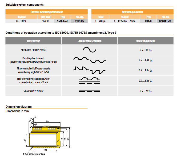
RCMA475LY has strong adaptability to different types of fault currents, and the working current range (relative alarm threshold I Δ n) is as follows to ensure monitoring reliability in complex load scenarios:
Specific description of current type, working current range (relative to I Δ n), typical application scenarios
AC current 50Hz sine wave AC current 0.5... 1 × I Δ n for ordinary motors and lighting loads
Pulsating DC current positive and negative half wave pulsating DC (including half wave rectified current) 0.5... 1.4 × I Δ n single-phase rectified charger
Phase controlled half wave current delay angle of 90 ° el/135 ° el for phase controlled rectification current 0.5... 1.4 × I Δ n thyristor speed control equipment
Half wave current of mixed DC current combined with 6mA smooth DC, 0.5... 1.4 × I Δ n rectified load with filtering
Smooth DC current Pure DC fault current 0.5... 2 × I Δ n Battery powered equipment, DC-DC converter
Model specifications and ordering information
(1) Core model differentiation
Products are classified into models based on power supply voltage, and different models are suitable for different power supply scenarios. When ordering, it is necessary to clearly specify the model and order number:
Model, Supply Voltage Range, Applicable Scenarios, Order Number
RCMA475LY 230V AC/DC Industrial Application+Civil Building B 9404 2002
RCMA475LY-13 90... 132V AC/DC Industrial Application B 9404 2004
RCMA475LY-21 9.6... 84V AC/DC Industrial Application B 9404 2014
RCMA475LY-23 77... 286V AC/DC Industrial Application B 9404 2015
Note: Other power supply voltage versions can be customized according to users' special needs. Please contact the manufacturer for confirmation.
(2) Recommended supporting components
To expand the functionality of the device, manufacturers provide dedicated supporting components that can be selected according to actual monitoring needs:
Component Name Function Description Model Order Number Key Parameters
External measuring instrument 0... 100% residual current ratio display 9604-4241 B 986 807 size 96 × 96mm, compatible with standard instrument panel installation
Measurement converter signal conversion (input → output) RK170 B 9804 1500 input 0... 400 µ A, output 0... 10V or 4... 20mA, compatible with PLC and DCS centralized monitoring systems
Installation and Operation Guide
(1) Installation points
Installation location: Choose an area with good ventilation, away from heat sources and strong electromagnetic interference sources, such as inside the distribution cabinet. The installation direction is not limited to ensure that the front panel is easy to operate and observe.
Wiring specifications: Strictly follow the wiring diagram to connect the power line, signal line, and load line. PE conductors must not pass through the built-in measuring current transformer. After wiring is completed, tighten the terminal screws to avoid loosening and poor contact.
Protective measures: The sealed transparent cover should be locked after the parameter settings are completed to prevent unauthorized personnel from tampering with the settings; Outdoor or dusty environments require additional protective covers to ensure a protection level of no less than IP30.
(2) Parameter setting steps
Threshold setting: Adjust the alarm threshold (30... 500mA) through the "x mA" potentiometer on the front panel. Rotate clockwise to increase and counterclockwise to decrease.
Mode switching: Set the warning ratio (50%/100% I Δ n1), warning delay (0s/1s), and relay mode (NO/NC) through DIP switches, with the white end of the switch indicating the effective position.
Delay setting: Adjust the alarm delay through the "t/s" potentiometer, switch the x1/x10 gear to select the delay range (0... 1s or 0... 10s).
Function test: Long press the "TEST/RESET" button (>2s) to start the test. The device should trigger the alarm relay action, and the LED bar graph should respond synchronously with the Alarm LED. After verifying that the device is functioning properly, short press to reset.
- YOKOGAWA
- Reliance
- ADVANCED
- SEW
- ProSoft
- WATLOW
- Kongsberg
- FANUC
- VSD
- DCS
- PLC
- man-machine
- Covid-19
- Energy and Gender
- Energy Access
- Renewable Integration
- Energy Subsidies
- Energy and Water
- Net zero emission
- Energy Security
- Critical Minerals
- A-B
- petroleum
- Mine scale
- Sewage treatment
- cement
- architecture
- Industrial information
- New energy
- Automobile market
- electricity
- Construction site
- HIMA
- ABB
- Rockwell
- Schneider Modicon
- Siemens
- xYCOM
- Yaskawa
- Woodward
- BOSCH Rexroth
- MOOG
- General Electric
- American NI
- Rolls-Royce
- CTI
- Honeywell
- EMERSON
- MAN
- GE
- TRICONEX
- Control Wave
- ALSTOM
- AMAT
- STUDER
- KONGSBERG
- MOTOROLA
- DANAHER MOTION
- Bentley
- Galil
- EATON
- MOLEX
- Triconex
- DEIF
- B&W
- ZYGO
- Aerotech
- DANFOSS
- KOLLMORGEN
- Beijer
- Endress+Hauser
- schneider
- Foxboro
- KB
- REXROTH
- YAMAHA
- Johnson
- Westinghouse
- WAGO
- TOSHIBA
- TEKTRONIX
- BENDER
- BMCM
- SMC
- HITACHI
- HIRSCHMANN
- XP POWER
- Baldor
- Meggitt
- SHINKAWA
- Other Brands
- UniOP
- KUKA
- IBA
- Beckhoff
- ADLINK
-
Beckhoff CX1100-0910 - Power Supply Module
-
Beckhoff C5210-0010 - Communication Module C5210
-
BECKHOFF KL1352 - Bus Terminal SET OF 2 FREE FAST SHIP
-
Beckhoff EL3058 - 8 x analog input single ended 4...20mA 85惟 shunt 12bit
-
Beckoff CX1100-0920 - UPS Module 24VDC (US SELLER) * *
-
BECKHOFF C6920-0000 - C69200000 PLC Moudule
-
Beckhoff CX5120-0115 - CPU controller module CX5120-0115
-
Unknown 15F5C1E-Y50A - Of Frequency Converters
-
Beckhoff AX5118-0000-0200 - Servo Drive HTP0
-
BECKHOFF AX5106-0000-0200 - Servo Drive
-
Beckhoff CX5240-0175 - Module (free) #U2327D YG
-
Beckhoff CP6607-0001-0000 - Compact PC Panel Economy Installation Operator 5,7 "
-
Beckhoff EP3744-0041 - 2022 EP37440041 Module
-
Beckhoff CP6209-0001-0020 - 6.5" PC Touch Screen Control Panel 24VDC
-
Beckhoff CX9020-0111 - /U900 +8x+2xEL3121+1x EL9410+3xEL1008+1x EL2008 Set
-
Beckhoff C6525-1030-0050 - Industrial PC
-
Beckoff CX1100-0920 - UPS Module 24VDC (US SELLER)
-
Beckhoff CX5010-0120 - CX5010 Processor Intel Atom Z510 B24
-
Siemens 6FC5203-0AF04-1BA1 - Operation Panel
-
Beckhoff CX5230-0175 - / 000029724 Embedded PC / Industrial PC on Rail
-
Beckhoff CP3916-0000 - industrielles Anzeige- und Bedienterminal
-
BECKHOFF CX1500-M310 - CX1000-N000 CX1000-0011 CX1000-C00L CX1100-0002 PLC Module
-
Beckhoff EL1872 - 16-channel digital input terminal
-
BECKHOFF EP2318-0001 - module
-
Beckhoff CX9020-0110 - Basic CPU Module
-
Beckhoff EL2564 - EtherCAT Terminal, 4-channel LED output, 5鈥?8VDC, 4A, RGBW
-
Beckhoff CX5130-0155 - /000105637 Automation Embedded PC
-
B&R 400 - Power Control Panel Rev D0 24 VDC
-
Beckhoff CX2020-0155 - module
-
Beckhoff CX9020-0115 - PLC Module
-
BECKHOFF EL6695 - PLC EL 6695
-
BECKHOFF EL7047 - PLC Modules
-
Beckhoff CX1000-0012 - Control HW 2.2 + CX1500-M310 + CX1000-C00L + CX1100-0002+
-
Beckhoff C6920-1039-0030 - control cabinet industrial PC CPU Celeron 1.90 GHz, 2 cores
-
BECKHOFF CX1100-0910 - PLC Module#
-
Beckhoff IL2301-B318-0000 - Coupler Box 4 Channel Digital Input |
-
Beckhoff CX7080 - Module
-
Beckhoff C6930-0060 - Industrial PC
-
Beckhoff CP7902-1060-0000 - Touchscreen 15 " CP7902
-
beckhoff CX9020-0111 - Controller module or UPS
-
Beckhoff CX8091 - PLC Module CX8091
-
Beckhoff C6640-1008-0030 - Control Cabinet Industrial PC
-
BECKHOFF CX1100-0920 - module
-
Beckhoff C9900-M921 - see pictures
-
BECKHOFF CP6829-0001-0000 - Touch Panel
-
BECKHOFF C6930-0060 - Industrial Computer
-
BECKHOFF CX8050 - PLC module
-
Beckhoff CP6202-0021-0020 - Touch Screen #
-
BECKHOFF AM3031-0C20-0000 - SERVO MOTOR
-
Unknown BCH1302N11A1C - Servo motor
-
Beckhoff EL2502 - 2-channel pulse width output terminal
-
Beckhoff EL6731 - Profibus Master / *Rev: 0025
-
Beckhoff CP3918-0010 - Control Panel
-
BECKHOFF CP2915-0010 - [24 MONTH WARRANTY] Control Panel
-
Beckhoff AX5203-0000-0202 - Servo Drive
-
Schneider TSXDSY64T2K - PLC OUTPUT MODULE
-
Beckhoff EP4174-0002 - Module-
-
Beckhoff IL2302-B318-0000 - Profibus Box
-
Beckhoff CP6709-0001-0000 - Touchpanel
-
BECKHOFF CX2030-0123 - Controller
-
Beckhoff CX9020-0111 - Processor Module
-
Beckhoff CX1020-0000 - CX Basic CPU Module
-
Beckhoff AX2003-AS - Servo Drive HTP0
-
Beckhoff C6240-1052-0040 - 4-086-06-3073 Industrial Computer CB1052-0003
-
Beckhoff EL1918 - 8 xTwinSAFE Input
-
Beckhoff AM8072-0R20-0000 - Servomotor
-
BECKHOFF AM8021-1B21-0000 - servo motor #T882 YS
-
Beckhoff EL6224 - 4 X Terminal IO-LINK
-
Beckhoff CX5140-0135 - embedded PC with Intel Atom processor 4 GB HW 3.6
-
Beckhoff CP7201-1000-0000 - Panel PC #
-
Beckhoff CX5130-0121 - Embedded-PC 4GB CPU Module HW 2.5 Industrial PC
-
Beckhoff AM8022-0D41-1002 - Servomotor
-
BECKHOFF CX2030-0130 - Module
-
BECKHOFF EL1872 - 16-channel digital input terminal
-
Unknown GXMMW.A203P33 - 1pc encoder
-
Beckhoff EL6631-0000 - EtherCAT Terminal 2-Port EL 6631
-
BECKHOFF C6925-0030 - Industrial Computer
-
Beckhoff CX8190 - A Module
-
BECKHOFF CX2040-0135 - CX2040-0135/000000927 CPU BASE MODULE i7 2715QE 2.1GHz --
-
BECKHOFF KL6023-0000 - Wireless adapter
-
Saia Burgess PCD7.F700 - PCD7F700 Communication Module
-
Beckhoff CX5130-0112 - CPU Module
-
BECKHOFF CX1020-N010 - CX1020-N000 CX1020-0111 CX1100-0004 EL2008 EL3064 EL4004
-
Beckhoff EP1819-0021 - A Module
-
Beckhoff CX2030-0120 - / 4gb with CX2100 0004
-
B&R X20-XC-0292 - Automation Powerlink Ethernet Bus Controller Module
-
Beckhoff BK3110 - One PLC Module
-
BECKHOFF KL3222 - PLC Module
-
BECKHOFF CX1500-M310 - CX1000-N000 CX1000-0011 CX1000-C00L CX1100-0002 PLC MODULE
-
Beckhoff CP3918-0010 - Control Panel
-
Beckhoff CX2030-0100-1002 - /4GB + CX2100 + CX2550 + CX2500-0060 + SSD
-
Beckhoff EP1816-0008 - PLC Module
-
Beckhoff CX5130-0112 - Module
-
Beckhoff Cx1500-m750 - CPU Hw: 1.4
-
BECKHOFF AX5112-0000-0200 - AX511200000200 Servo Driver
-
Beckhoff EL3751 - EtherCAT Terminal 1 Channel Analog Input Multifunction 24 Bit
-
Beckhoff CX1100-0002 - Power Supply Module
-
Beckhoff CP3916-1016-0010 - Control Panel
-
BECKHOFF CX9001-1101 - #NAME?
-
Beckhoff EP3174-0002 - EtherCAT Box Module
-
Beckhoff C6030-0070 - servo drive
-
Beckhoff CX2020-0120 - /4GB CPU, CX2100-0904, 3x EL6900, EL1904, 16GB Memory
-
BECKHOFF C6110 - BOX-PC 113608
-
BECKHOFF EK1914 - module #P
-
Beckhoff C6140 - Ipox IP-4GVI63 + CH7009A_DVI_TV + SIEMENS A5E00369843 + WD800AAJB
-
Beckhoff CX5020-0111 - controller Good quality
-
BECKHOFF C6015-0010 - / 6559380 ULTRA-COMPACT INDUSTRIAL PC ()
-
Beckhoff AX5203-0000-0200 - PLC module
-
Beckhoff EL2872 - 16-channel digital output terminal
-
BECKHOFF C3640-0000 - Panel Industrial PC 100/240VAC 128MB E0122L
-
Beckhoff CX8031 - Module
-
Beckhoff CX5020-0120-1002 - PLC module#
-
Beckhoff C6140 - M845B + SIEMENS A5E00369843 + C9900_A159_1 + AUTOMATA CAN PCI 1N
-
BECKHOFF AX5112-0000-0200 - Servo Drive*ie
-
B&R ECPA42-01 - Analog Output Module 4-Channel, +/- 10V Output Signal, 20mA Max
-
Beckhoff EL6631-0010 - PLC Module
-
BECKHOFF C6930-0070 - CONTROL CABINET INDUSTRIAL PC
-
BECKHOFF AX5112-0000-0200 - AX511200000200 Servo Driver
-
BECKHOFF EK9000 - Programmable Logic Controller Module EK9000 EK9000
-
BECKHOFF C6920-1028-0000 - Industrial computer
-
Beckhoff CX2030-0120 - controller Module
-
Beckhoff BX8000-0000 - Bus Terminal Controller HW 4.4
-
B&R 3NC154.60-2 - Positioning Module#
-
BECKHOFF CX1020-0122 - PLC module
-
Beckhoff AM3032-0D40-0000 - Servo Motor
-
BECKHOFF CX5020-0111 - CPU Module CX5020-0111
-
Beckhoff CB1051 - G5 Motherboard
-
BECKHOFF KL2641 - 1-channel relay output terminal

K-JIANG

Add: Jimei North Road, Jimei District, Xiamen, Fujian, China
Tell:+86-15305925923