
K-WANG


ABB REP57160001-KX DSDO 131 Digital Output Unit
ABB REP57160001-KX DSDO 131 Digital Output Unit
Brand background
ABB is a leading global enterprise in the field of electrical and automation technology, with business covering multiple key areas such as power, industrial automation, motion control, robotics and discrete automation, and energy. Since its establishment in 1891, ABB has always been driven by innovation, providing efficient and reliable solutions to global customers with advanced technology, excellent product quality, and a comprehensive service system. ABB has accumulated profound technical expertise in the manufacturing of industrial automation control equipment, and its products are widely used in industrial production, infrastructure construction and other projects around the world. The REP57160001-KX DSDO 131 digital output unit is one of its high-quality products in the field of automation control, reflecting the brand's unremitting pursuit of technological innovation and product reliability.
Product Overview
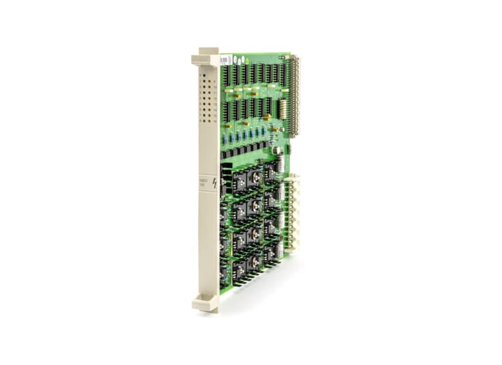
The ABB REP57160001-KX DSDO 131 digital output unit is a core component designed specifically for industrial automation control systems. It is mainly used to convert digital signals from control systems into drive signals that can be received by external devices, achieving precise control of various actuators. This digital output unit adopts a modular design, with the characteristics of compact structure, powerful functions, and high stability. It can be seamlessly integrated with ABB and other brands' PLC, DCS and other control systems, and is widely used in multiple industries such as power, chemical, manufacturing, transportation, etc. It plays a key role in industrial automation production processes and can effectively improve the automation level and control accuracy of the production process.
Specification parameters
Number of channels: 16 digital output channels, capable of controlling 16 external devices simultaneously, meeting control requirements in various industrial scenarios
Output signal type
Support dry contact output, capable of reliably controlling the on/off of relays, contactors, and other equipment; It can also output a 24V DC level signal to directly drive low-voltage devices such as small solenoid valves and indicator lights
Output current: The maximum output current of a single channel can reach 2A, which can drive high-power load devices; Isolation between channels to avoid signal interference and ensure stable system operation
Isolation voltage: The isolation voltage between channels and between channels and the common terminal can reach up to 500V AC, with good electrical isolation performance, effectively preventing electrical interference and equipment damage
Working voltage: The power supply voltage is 24V DC (± 10%), which can adapt to a certain range of voltage fluctuations and ensure normal operation even in unstable power supply environments
Communication interface: Supports various industrial communication protocols such as PROFIBUS DP and Modbus RTU, and can perform high-speed and stable data communication with control systems through standard RS485 interfaces; Remote monitoring and parameter setting can also be achieved through Ethernet interface (supported by some models)
Working temperature range: -20 ℃ -60 ℃, suitable for temperature conditions in most industrial environments; Can maintain stable working performance in high or low temperature environments
Protection level: IP20 protection level, which can prevent dust from entering the interior of the equipment; If you need to use it in more harsh environments, you can choose models with higher protection levels
Working principle
After the control system issues digital control commands, the commands are transmitted to the DSDO 131 digital output unit through the communication interface. The microprocessor inside the unit parses and processes the received instructions, and controls the corresponding output channels according to the instruction requirements. For the dry contact output channel, the microprocessor controls the on/off of the relay coil to achieve the closure and disconnection of the dry contact; For the level signal output channel, the corresponding high-level or low-level signal is output through the internal electronic switch circuit. During the process of outputting signals, the isolation circuit inside the unit ensures electrical isolation between each output channel and between channels and the common terminal, preventing signal interference and electrical faults. At the same time, the fault diagnosis circuit monitors the current, voltage and other parameters of the output channel in real time. Once an abnormal situation is detected, the fault information is immediately fed back to the microprocessor. The microprocessor takes corresponding protective measures according to the preset fault handling program and sends the fault information to the control system through the communication interface, achieving safe protection and stable operation of the entire system.
Key advantages
(1) High reliability and stability
Using high-quality electronic components and advanced manufacturing processes, rigorous quality inspection and testing are carried out to ensure that the REP57160001-KX DSDO 131 digital output unit has excellent reliability and stability. In harsh industrial environments such as high temperature, high humidity, and strong electromagnetic interference, it can still operate stably for a long time, effectively reducing equipment failure rates, minimizing production downtime caused by equipment failures, ensuring the continuity and stability of industrial production, and providing strong guarantees for the production efficiency of enterprises.
(2) Powerful compatibility and scalability
Supports multiple industrial communication protocols and is seamlessly compatible with mainstream control systems such as PLC and DCS in the market, making it convenient for users to flexibly choose between different automation control projects. At the same time, modular design enables the digital output unit to have good scalability, and users can flexibly adjust the input and output points of the system by increasing or decreasing the number of modules according to actual needs, meeting the control requirements of industrial projects of different scales. Whether it is a small automated production line or a large complex industrial control system, it can be easily handled, reducing the cost of system upgrades and transformations for enterprises.
(3) Efficient and convenient maintainability
Equipped with comprehensive fault diagnosis and display functions, when equipment malfunctions, the fault point can be quickly located through indicator lights or communication interfaces, greatly reducing the time for troubleshooting. At the same time, the modular structure design makes the replacement of faulty modules more convenient, without the need for professional tools and complex operating procedures, allowing for quick disassembly and installation of modules, reducing equipment maintenance time and labor costs. In addition, it supports online programming and parameter settings, allowing users to adjust device functions and update programs without interrupting system operation, improving equipment maintenance efficiency and flexibility of use.
Precautions
(1) Installation requirements
When installing, a dry, well ventilated environment without severe vibration should be selected, away from high temperature, humidity, dust, and strong electromagnetic interference sources. Strictly follow the installation steps in the product manual to ensure that the digital output unit is securely installed on the standard guide rail or mounting plate of the control cabinet. During the installation process, avoid colliding or squeezing the equipment to prevent damage to internal components. At the same time, ensure that the installation location of the equipment is easy to operate and maintain, and reserve sufficient space for wiring and heat dissipation.
(2) Electrical connection
Before making electrical connections, be sure to cut off all power sources to ensure safe operation. Connect the power supply, communication lines, and output signal lines correctly according to the wiring diagram, paying attention to distinguishing the connection ports and polarities of different cables to prevent equipment damage or system failure caused by incorrect connections. Use cables that meet the specifications, and take proper measures to secure and protect the cables to prevent them from being pulled or worn by external forces. For communication cables, shielded wires should be used and the shielding layer should be properly grounded to reduce the impact of electromagnetic interference on communication quality.
(3) Programming and Debugging
During the programming and debugging process, it is necessary to use ABB's official designated programming software and tools, and follow relevant programming specifications and standards. Before writing a program, carefully read the product manual to understand the functions and operating methods of the digital output unit. Thoroughly test and validate the written program to ensure the correctness of the control logic. During the debugging process, gradually check whether the various functions of the device are normal, such as whether the output signal is accurate, whether the communication is stable, etc. If any problems are found, they should be promptly investigated and resolved to ensure that the equipment can operate normally.
(4) Daily maintenance
Regularly inspect and maintain the digital output unit, checking the appearance of the equipment for damage, loose wiring, and normal display of indicator lights. Timely clean the dust on the surface of the equipment to ensure good heat dissipation. Regularly check the working status and operating parameters of the equipment, such as output current, voltage, etc., and promptly handle any abnormalities found. According to the requirements of the product manual, regularly calibrate and maintain the equipment to extend its service life and ensure its stable operation.
- YOKOGAWA
- Reliance
- ADVANCED
- SEW
- ProSoft
- WATLOW
- Kongsberg
- FANUC
- VSD
- DCS
- PLC
- man-machine
- Covid-19
- Energy and Gender
- Energy Access
- Renewable Integration
- Energy Subsidies
- Energy and Water
- Net zero emission
- Energy Security
- Critical Minerals
- A-B
- petroleum
- Mine scale
- Sewage treatment
- cement
- architecture
- Industrial information
- New energy
- Automobile market
- electricity
- Construction site
- HIMA
- ABB
- Rockwell
- Schneider Modicon
- Siemens
- xYCOM
- Yaskawa
- Woodward
- BOSCH Rexroth
- MOOG
- General Electric
- American NI
- Rolls-Royce
- CTI
- Honeywell
- EMERSON
- MAN
- GE
- TRICONEX
- Control Wave
- ALSTOM
- AMAT
- STUDER
- KONGSBERG
- MOTOROLA
- DANAHER MOTION
- Bentley
- Galil
- EATON
- MOLEX
- Triconex
- DEIF
- B&W
- ZYGO
- Aerotech
- DANFOSS
- KOLLMORGEN
- Beijer
- Endress+Hauser
- schneider
- Foxboro
- KB
- REXROTH
- YAMAHA
- Johnson
- Westinghouse
- WAGO
- TOSHIBA
- TEKTRONIX
- BENDER
- BMCM
- SMC
- HITACHI
- HIRSCHMANN
- XP POWER
- Baldor
- Meggitt
- SHINKAWA
- Other Brands
- UniOP
- KUKA
- IBA
- Beckhoff
- ADLINK
-
ADLINK HPCI-14S12U - Industrial Control Backplane 12PCI Backplane PCI-14S Passive Backplane
-
ADLINK PCIe-GIE74C - image acquisition card 4-CH GigE Vision PoE+ Frame Grabber
-
ADLINK PCI-8164 - control card 4-Axis Advanced Motion Controller Board
-
ADLINK PCIe-U304 - 4 Port USB3 PCIe Frame Grabbers USB Screw Hole Card
-
ADLINK PCI-9112 - Multi-Function Data Acquisition Card DAQ Card
-
ADLINK PCI-7432 - 51-12013-0A50 4-CH Isolated Numérique I/O PCI Cartes Digital I/O Card
-
ADLINK PCA-6106P3-0C1 REV.C1 - backplane 6-Slot Passive Backplane Board
-
ADLINK PCI-7224 - 24-CH Opto-Isolated Digital I/O PCI Board
-
ADLINK CPCI-7433R(G) - Digital Input Board Rear I/O CompactPCI Card
-
ADLINK EBP-13E4 - 51-46703-0A30 Industrial PC Backplane Passive Backplane
-
ADLINK PCIE-HDV62 - Image acquisition card High Definition Video Frame Grabber
-
ADLINK EBP-13E4 - 51-46703-0A30 Industrial Backplane Board Passive Backplane
-
ADLINK 90111-B1 / CPCI-6770 - PCB CPU MODULE CompactPCI Single Board Computer
-
ADLINK PCI-7248 - DATA ACQUISITION PCI CARD 48-CH Parallel Digital I/O Board
-
ADLINK PCI-7230 - 51-12003-0a50 board PCI7230 32-CH Isolated Digital I/O Card
-
ADLINK PCI2A000CB - 51-20000-0B30 Multi-Function DAQ Card Baseboard
-
ADLINK PCI-8134-005 - 4-Axis Motion Controller Card
-
ADLINK PCI-7224 - 24-CH Opto-Isolated Digital I/O PCI Card
-
ADLINK PCI-7434 - 64-CH Isolated Digital Output Card
-
ADLINK PCI-8132 - motion control card 2-Axis Servo & Stepper Controller
-
ADLINK PCI-8134 - Motion Controller PCI Card 4-Axis Controller Board
-
ADLINK PCI-8164 - Motion Control Card 51-12406-0A40 4-Axis Controller
-
ADLINK 51-12001-0C20 - Circuit Board Data Acquisition Interface Module Hardware
-
ADLINK NuPR0-840 - industrial control motherboard Full-Size PICMG CPU Board
-
ADLINK PCI-7444 - 51-12023-0A10 card 128-CH Isolated Digital Output Board
-
ADLINK PCI-1612B - data acquisition card 4-Port RS-232/422/485 Serial Communication Card
-
ADLINK PCI-6208V 009 - 8/16-CH 16-Bit Analog Output Cards PCB-I-E-482=6BX3
-
ADLINK NUPRO-935A/LV - industrial control motherboard Full-Size PICMG SBC Board
-
ADLINK PCI-9114DG - Multi-Function DAQ Card Data Acquisition PCI Card
-
ADLINK ACL-7130 - Data acquisition card Isolated Digital I/O Board
-
ADLINK ABX-6300D-4E1-BP - board ABX6300D4E1BP Video Interface Expansion Card
-
ADLINK CPCI-6940 - CPCI-6940/D1539/M16-0(EA)-000E 6U CompactPCI Processor Board
-
ADLINK NuPRO-760 - industrial control motherboard Half-Size PICMG SBC CPU Board
-
ADLINK IMB-M42H (G)-0020 - industrial control motherboard LGA1155 Micro-ATX Mainboard
-
ADLINK RTV-24 / PCI-MP4S - 51-12519-1C30 4-Channel Real Time Video Capture Board
-
ADLINK PCI-8134 - 4-Axis Servo & Stepper Motion Controller Card
-
ADLINK MXC-6101D - V.PC000.002.ST.00 Box PC Configurable Embedded Computer
-
ADLINK PCI-8134A - 51-12421-0A10 Motion Control Card 4-Axis Controller Card
-
ADLINK DIN-100S / DIN-100SA1 - Technology SCSI-II TB 100-PIN Terminal Block Board
-
ADLINK DIN-812M001 / DIN812M001 - 51-14034-0A1 51140340A1 Terminal Module Breakout Interface
-
ADLINK PCI-8164 - Servo motion control 4-Axis Advanced Controller Card
-
ADLINK PCIe-GIE64 - Acquisition card GigE Vision PoE+ Frame Grabber
-
ADLINK M-302 - Industrial control motherboard ATX PC Board Mainboard
-
ADLINK PCI-8134 - Motion Controller PCI Card 4-Axis Controller Board
-
ADLINK PCI-RTV24 - Image capture card Analog Video Frame Grabber
-
ADLINK PCI-8102 - Motion control card 2-Axis Servo & Stepper Controller Board
-
ADLINK PCI-9112 REV.B1 - Card Multi-Function Data Acquisition Card
-
ADLINK HSI-DI32-M-N / HSL-TB32-M-DIN - Discrete I/O MODULE Distributed Automation Module System
-
ADLINK PCI-7296 - IO card REV.A3 96-CH Parallel Digital I/O Card
-
ADLINK DIN-814P-A4 / 814Y - terminal board Motion Control Interface Block
-
ADLINK DIN-814P-A4 - 51-14056-0A10 PCB-I-E-2736=ZA01 Screw Terminal Board Breakout
-
ADLINK M-322 - motherboard Industrial Control Computer Mainboard
-
ADLINK NUPRO-406 REV:B1 - industrial control motherboard Full-Size PICMG CPU Board
-
ADLINK AMP-204C - card DSP-Based 4-Axis Advanced Pulse-Train Controller
-
ADLINK HPCI14S REV.B1 - industrial computer baseboard 14-Slot Passive Backplane
-
ADLINK PCI-7250 - 8-CH Relay Output & 8-CH Isolated DI PCI Card
-
ADLINK EBP-13E2 - baseplate Passive Backplane Industrial Computer Chassis Board
-
ADLINK LPCI-3488A - PCI-GPIB card 51-12801-0A30 acquisition card IEEE-488 Interface Board
-
ADLINK PCI-6216V-GL - 51-12201-0C30 16-CH 16-Bit Voltage Analog Output Card
-
ADLINK ACL-8454 - 16-CH Isolated Digital I/O & 4-CH Counter Card
-
ADLINK HPCI-9S7U - backplane Passive Backplane Compatible with NuPRO-A301 852 841 842
-
ADLINK DAQ-2010-007 - Simultaneous-Sampling Multi-Function Data Acquisition Card
-
ADLINK MP-C154 - 51-64205-0A10 Motion Control Card 4-Axis Controller Board
-
ADLINK MXE-202/mSSD16B/WiFi-BT - Matrix Rugged I/O Platform Embedded Fanless Computer
-
ADLINK CM-920-R-17 - PC/104-Plus Single Board Computer Module Intel Celeron M
-
ADLINK PCI-7250 NSMP - 8-CH Relay Output & 8-CH Isolated DI Card
-
ADLINK PCI-8164 - 4-Axis Motion Controller PCI Card W/ Cable and Breakout Box
-
ADLINK EMX-100 - Ethernet-based 4-axis Motion Controllers Distributed Motion Module
-
ADLINK PCI-8134A - Press control card 4-Axis Motion Controller Board
-
ADLINK M-845EG REV:3.2 - industrial motherboard Pentium 4 Socket 478 Micro-ATX
-
ADLINK PCI-9114A Rev A2 DG - card High-Resolution Multi-Function Data Acquisition Board
-
ADLINK IEC-915GV - REV 1.1 Industrial motherboard Socket 478 CPU Board
-
ADLINK PCI-9111DG(G) - Data Acquisition Card Multi-Function DAQ Card
-
ADLINK HPCI-15S10 REV:B2 - Industrial computer base plate Passive Backplane Board
-
ADLINK NuPR0-840 / NuPR0-840DV - industrial control motherboard Full-size PICMG CPU Board
-
ADLINK RTV-24 / PCI-MP4S - 51-12519-1C30 4-Channel Real Time Video Capture Board
-
ADLINK NUPRO-780 - industrial control motherboard Pentium III Single Board Computer
-
ADLINK PCI-7296 - 0050 card 96-CH Opto-Isolated Parallel DIO Card Set
-
ADLINK NUPRO-780 - industrial control motherboard PICMG Full-Size SBC
-
ADLINK PCI-7248 - 51-12006-0A3 002 Pci 7248 48-CH Parallel Digital I/O Card
-
ADLINK PCI-7230 - 32-CH Isolated Digital I/O Card
-
ADLINK AMP-204C - motion control card 4-Axis Advanced Controller Board
-
ADLINK PCI-1714UL - Card Ultra High-Speed 4-CH Simultaneous Sampling DAQ
-
ADLINK NuPRO-E330 - industrial computer equipment motherboard PICMG 1.3 SHB SBC
-
ADLINK AMP-204C - DSP-Based 4-Axis Advanced Pulse-Train Motion Controller Module
-
ADLINK PCI-7256 - 001 51-12206-0A2 REV.A2 LPCI-7256 16-CH Latching Relay Output Card
-
ADLINK ND6050 - NUDAM DIGITAL I/0 MODULE Distributed I/O Unit
-
ASEM BM100 - Box PC Embedded Fanless Industrial Computer
-
ADLINK PCI-7250 - PCI Acquisition Card 8-CH Relay Output & Isolated DI Board
-
ADLINK PCI-8164 - Servo motion control 4-Axis Controller Card
-
ADLINK NuPRO-A40H - Industrial Motherboard 51-41807-1A30 OSP LGA1155 H61
-
ADLINK ADMAX X300 SERVER - 51066010-0A30 motherboard Multi-Processor Mainboard
-
ADLINK CMe-GIE62+ - 51-32903-0A30 control card PC/104-Plus GigE Vision Frame Grabber
-
ADLINK NUPRO-780 - industrial control motherboard Full-Size PICMG SBC CPU Board
-
ADLINK ETX-AT-N270-18/GKTEL - 51-71111-OB10 motherboard ETX CPU Module Board
-
ADLINK DIN-812M - interface module Terminal Block Connection Board
-
ADLINK IMB-M42H - industrial control motherboard LGA1155 Micro-ATX Mainboard
-
ADLINK PXIS-2508 - 8-slot 3U PXI Instrument Chassis Power Hardware Assembly
-
ADLINK AMP-208C - Motion Control card DSP-Based 8-Axis Pulse-Train Controller
-
ADLINK PCI-9111 / PCI-9111DG - Multi-Function Data Acquisition Card DAQ Board
-
ADLINK IEEE-488 GPIB card - Bus Interface Controller Communication Board
-
ADLINK RTV-24 - 51-12519-1C30 image acquisition card Video Frame Grabber Card
-
ADLINK TB-24P/24-01 - Board 24 Way Screw Terminal Breakout Board
-
ADLINK HSL-DI16DO16-DB-NN - 51-23015-0A40 Distributed Discrete I/O Module Set
-
ADLINK PCI-7442 - switch quantity card data acquisition card 64-CH Isolated Card
-
ADLINK ACL-7130 REV. B2 - industrial control capture card Isolated Digital I/O PCI Card
-
ADLINK PCI-6S / PCI6S - Backplane 6-Slot Passive Backplane Chassis Board
-
ADLINK ACL-8113A - card Isolated Digital Input Card
-
ADLINK CPCI-6208V-003 - board cPCI CompactPCI 8-CH Analog Output Card
-
ADLINK DIN-100S-01(G) - SCSI 100-Pin Terminal Block Interface Board
-
ADLINK PCI-7433 - Isolated Digital Input Card 64-CH
-
ADLINK PCI-9812 - Synchronous sampling analog input card High-Speed DAQ Board
-
ADLINK PCI-7434 REV.B1 - PLOTECH PCB-I-E-1182=6EX2 64-CH Isolated Digital Output Card
-
ADLINK PCIe-RTV24 - 51-18016-0A20 4-CH Real-Time Video Capture Card PCIe Frame Grabber
-
ADLINK PCI-8144 / PCI-8144N - Motion control card 4-Axis Stepper Motor Controller
-
ADLINK DIN-68S-01 - terminal board 68-Pin Connector Terminal Block
-
ADLINK MP-C154 - Motion control card 4-Axis Advanced Controller Card
-
ADLINK PCI-7248 (G) - Motherboard 48-CH Parallel Digital I/O Card
-
ADLINK MXE-1301(G) - Intel Atom D2550+NM10 MXE 1300 Series 93-4130-0030 Embedded Computer
-
ADLINK PRO-841 Rev 2.0 / PRO-060907000670 - CPU 2.26GHz & RAM Industrial PC Board
-
ADLINK NuPRO-E330 - Industrial Motherboard System Host Board PICMG 1.3 SHB
-
ADLINK EBP-13E2 - Passive Backplane Industrial Chassis Baseboard
-
ADLINK PCI-8154 - 4-axis Motion Control Card Servo & Stepper Controller Board
-
ADLINK NuPrO-596 REV.B1 - industrial control motherboard Half-size PICMG CPU Board
-
ADLINK PCI-7852 / PCI-7851 - PLOTECH High-Speed Link Control Card Interface Board
-
ADLINK PCI-9112 - 51-12252-0D20 data acquisition card Multi-Function DAQ
-
ADLINK PCI-9112 - Circuit Board 51-12252-0C20 Multi-Function Data Acquisition Card
-
ADLINK NUPRO-761 REV:1.1 - industrial control motherboard PICMG Full-Size CPU Board

K-JIANG

Add: Jimei North Road, Jimei District, Xiamen, Fujian, China
Tell:+86-15305925923