
K-WANG


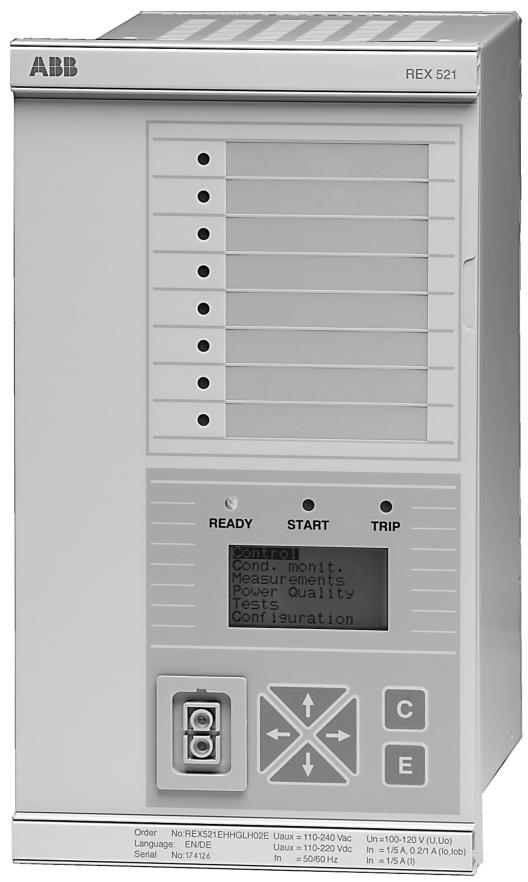
ABB Protection Relay REX 521
ABB Protection Relay REX 521
Product positioning and purpose
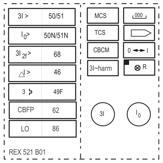
REX 521 is a high-performance digital protection relay launched by ABB, designed specifically for medium voltage (MV) power systems, suitable for the protection, measurement, and control of equipment such as substations, transmission and distribution lines, transformers, motors, and busbars. Its modular design supports multiple standard configurations and can flexibly adapt to scenarios such as radial networks, ring networks, and compensating grounding systems, meeting the needs of selective protection, automatic reclosing, and synchronous inspection.
Core functional features
Multi dimensional protection function
Overcurrent protection: Supports three-stage non directional/directional overcurrent protection (3I>, 3I>>, 3I>>>), and can be configured with IDMT (inverse time limit) or DT (definite time limit) characteristics.
Ground fault protection: Non directional/directional ground fault protection (Io>, Io>>, Io>>and directional versions), suitable for different grounding systems (isolated, resistive, resonant grounding).
Voltage and frequency protection: overvoltage/undervoltage (3U>, 3U<<), frequency abnormality (f1, f2) protection, to prevent equipment damage caused by grid voltage fluctuations or frequency offset.
Motor and special protection: thermal overload (3Ithdev>), start-up supervision (Is2t n<), phase sequence protection (3I()), etc., designed specifically for motor drive systems.
Accurate measurement and monitoring
Real time measurement of three-phase current/voltage, power, energy, and harmonics (supporting THD/TDD analysis) with an accuracy of ± 1%.
The disturbance recording (DREC) function can capture fault waveforms, support pre triggering and multi cycle recording, and facilitate fault analysis.
Flexible control and communication
8-channel programmable digital input/multi-channel relay output, supporting circuit breaker control, interlocking logic, and alarm signal output.
Compatible with communication protocols such as Modbus and DNP 3.0, it can be connected to substation automation systems (SCADA) for remote monitoring.
Hardware specifications
Hardware version
Basic: Basic protection function, suitable for simple distribution networks.
Medium: Increase directional protection and support more complex grounding systems.
High/Sensor: Advanced features including synchronization check, motor protection, etc. Some configurations support sensor input.
Rating
Current input: 1A/5A (measurement), 0.2A/1A (ground fault).
Voltage input: 100V/110V/115V/120V (phase voltage/line voltage).
Auxiliary power supply: DC 24-250V or AC 24-240V.
Output Relay
High speed trip relay (HSPO1): 4 normally open+4 normally closed, contact capacity 5A/250V AC.
Power output relay (PO1-PO3): 3 sets of conversion contacts, capacity 10A/250V AC.
Signal output relay (SO1-SO2): 2 sets of conversion contacts, capacity 5A/250V AC.
Protection function parameters
1. Overcurrent protection
Three stage non directional:
3I>(low setting): Starting current 0.10-5.00 x In, operating time 0.05-300s (supports IDMT/DT characteristics).
3I>>(high setting): starting current 0.10-40.00 x In, operating time 0.05-300s.
3I>>(instantaneous): starting current 0.10-40.00 x In, instantaneous action (<40ms).
Directional overcurrent:
3I>-->/3I>>-->: Starting current 0.05-40.00 x In, basic angle adjustable from 0 ° to 90 °, supporting forward/reverse action.
2. Ground fault protection
Non directional:
Io>(low setting): Starting current 1.0-500% In, operating time 0.05-300s seconds.
Io>>(high setting): Starting current 0.10-12.00 x In, operating time 0.05-300s seconds.
Io>>(instantaneous): Starting current 0.10-12.00 x In, instantaneous action.
directional:
Io>-->/Io>-->/Io>>-->: Starting current 1.0-500% In, basic angle -90 ° -60 ° adjustable, supports Uo/Io phase judgment.
3. Voltage protection
Overvoltage:
3U>(low setting): starting voltage 0.10-1.60 x Un, operating time 0.05-300s.
3U>>(high setting): starting voltage 0.10-1.60 x Un, operating time 0.05-300s.
Undervoltage:
3U<(low setting): starting voltage 0.10-1.20 x Un, operating time 0.1-300s.
3U<<(high setting): starting voltage 0.10-1.20 x Un, operating time 0.1-300s.
4. Other protections
Frequency protection (f1/f2): frequency range 25-75Hz, df/dt detection accuracy ± 100mHz/s.
Motor protection:
Thermal overload (3Ithdev>): Dual time constant model, temperature range -50 ° C-150 ° C.
Start supervision (Is2t n<): Start current 1.0-10.0 x In, start time 0.3-250s.
Phase sequence protection (3I()/U1U2<>_1): detects phase sequence reversal or imbalance, with an operation time of 0.1-10 seconds.
Measurement and monitoring parameters
Electrical Measurement
Current/Voltage: True RMS measurement with an accuracy of ± 1% (within the rated range).
Power/Energy: Fundamental active power (kW), reactive power (kVAr), accuracy ± 0.5%.
Frequency: Measurement range 10-75Hz, accuracy ± 10mHz.
Disturbance Record (DREC)
Record length: up to 1066 cycles (21.3s at 50Hz), supporting pre triggering (0-100%).
Trigger methods: digital input, overcurrent/overvoltage threshold, manual or communication trigger.
Power Quality Monitoring
PQ 3Inf: Current Harmonics (THD/TDD), supports 1-13 harmonics, with an accuracy of ± 1% (1-10 times).
PQ 3Unf: Voltage harmonics, compliant with EN 50160 standard, accuracy ± 0.3% (1-10 times).
Control and Interface
digital input
8 programmable inputs, supporting inversion and pre delay (0-1000ms).
The functions include: reset, blocking, disturbance triggering, main tripping, and 16 other functions.
communication interface
Supports Modbus and DNP 3.0 protocols, with optional CANopen and Ethernet interfaces (requiring module expansion).
Environment and Certification
Working temperature: -25 ° C -+70 ° C (non condensing).
Protection level: IP40 (front panel), IP20 (back).
Certification: Compliant with standards such as IEC 61850 and EN 61000-6-2, suitable for industrial grade electromagnetic compatibility environments.
Product advantages
High reliability and safety
Compliant with IEC 61850 standard, supports redundant design, and adapts to industrial electromagnetic compatibility environment (-25 ℃~+70 ℃ working temperature).
Built in trip circuit supervision (TCS1) and circuit breaker wear calculation (CB wear 1) enhance equipment status monitoring capability.
Usability and Configurability
Visualize configuration through HMI or Relay Setting Tool, support batch import/export of parameters, and reduce debugging time.
Standard configuration presets typical scenario parameters to reduce the difficulty of project implementation.
Typical application scenario parameters
Outgoing feeder: Basic B01, 3I>Starting current 1.2 x In, operating time 0.5s; Io>Starting current 5% In
Motor protection: High H07, thermal overload time constant of 10 minutes, starting current of 6 x In, starting time of 15 seconds
Busbar segmenter: High H03, 3I>>Starting current 2.0 x In, synchronous check voltage difference ≤ 5% Un
Incoming feeder: High H08, 3U>starting voltage 1.15 x Un, operating time 60s; 3U<starting voltage 0.85 x Un
- YOKOGAWA
- Reliance
- ADVANCED
- SEW
- ProSoft
- WATLOW
- Kongsberg
- FANUC
- VSD
- DCS
- PLC
- man-machine
- Covid-19
- Energy and Gender
- Energy Access
- Renewable Integration
- Energy Subsidies
- Energy and Water
- Net zero emission
- Energy Security
- Critical Minerals
- A-B
- petroleum
- Mine scale
- Sewage treatment
- cement
- architecture
- Industrial information
- New energy
- Automobile market
- electricity
- Construction site
- HIMA
- ABB
- Rockwell
- Schneider Modicon
- Siemens
- xYCOM
- Yaskawa
- Woodward
- BOSCH Rexroth
- MOOG
- General Electric
- American NI
- Rolls-Royce
- CTI
- Honeywell
- EMERSON
- MAN
- GE
- TRICONEX
- Control Wave
- ALSTOM
- AMAT
- STUDER
- KONGSBERG
- MOTOROLA
- DANAHER MOTION
- Bentley
- Galil
- EATON
- MOLEX
- Triconex
- DEIF
- B&W
- ZYGO
- Aerotech
- DANFOSS
- KOLLMORGEN
- Beijer
- Endress+Hauser
- schneider
- Foxboro
- KB
- REXROTH
- YAMAHA
- Johnson
- Westinghouse
- WAGO
- TOSHIBA
- TEKTRONIX
- BENDER
- BMCM
- SMC
- HITACHI
- HIRSCHMANN
- XP POWER
- Baldor
- Meggitt
- SHINKAWA
- Other Brands
- UniOP
- KUKA
- IBA
- Beckhoff
- ADLINK
-
ADLINK HPCI-14S12U - Industrial Control Backplane 12PCI Backplane PCI-14S Passive Backplane
-
ADLINK PCIe-GIE74C - image acquisition card 4-CH GigE Vision PoE+ Frame Grabber
-
ADLINK PCI-8164 - control card 4-Axis Advanced Motion Controller Board
-
ADLINK PCIe-U304 - 4 Port USB3 PCIe Frame Grabbers USB Screw Hole Card
-
ADLINK PCI-9112 - Multi-Function Data Acquisition Card DAQ Card
-
ADLINK PCI-7432 - 51-12013-0A50 4-CH Isolated Numérique I/O PCI Cartes Digital I/O Card
-
ADLINK PCA-6106P3-0C1 REV.C1 - backplane 6-Slot Passive Backplane Board
-
ADLINK PCI-7224 - 24-CH Opto-Isolated Digital I/O PCI Board
-
ADLINK CPCI-7433R(G) - Digital Input Board Rear I/O CompactPCI Card
-
ADLINK EBP-13E4 - 51-46703-0A30 Industrial PC Backplane Passive Backplane
-
ADLINK PCIE-HDV62 - Image acquisition card High Definition Video Frame Grabber
-
ADLINK EBP-13E4 - 51-46703-0A30 Industrial Backplane Board Passive Backplane
-
ADLINK 90111-B1 / CPCI-6770 - PCB CPU MODULE CompactPCI Single Board Computer
-
ADLINK PCI-7248 - DATA ACQUISITION PCI CARD 48-CH Parallel Digital I/O Board
-
ADLINK PCI-7230 - 51-12003-0a50 board PCI7230 32-CH Isolated Digital I/O Card
-
ADLINK PCI2A000CB - 51-20000-0B30 Multi-Function DAQ Card Baseboard
-
ADLINK PCI-8134-005 - 4-Axis Motion Controller Card
-
ADLINK PCI-7224 - 24-CH Opto-Isolated Digital I/O PCI Card
-
ADLINK PCI-7434 - 64-CH Isolated Digital Output Card
-
ADLINK PCI-8132 - motion control card 2-Axis Servo & Stepper Controller
-
ADLINK PCI-8134 - Motion Controller PCI Card 4-Axis Controller Board
-
ADLINK PCI-8164 - Motion Control Card 51-12406-0A40 4-Axis Controller
-
ADLINK 51-12001-0C20 - Circuit Board Data Acquisition Interface Module Hardware
-
ADLINK NuPR0-840 - industrial control motherboard Full-Size PICMG CPU Board
-
ADLINK PCI-7444 - 51-12023-0A10 card 128-CH Isolated Digital Output Board
-
ADLINK PCI-1612B - data acquisition card 4-Port RS-232/422/485 Serial Communication Card
-
ADLINK PCI-6208V 009 - 8/16-CH 16-Bit Analog Output Cards PCB-I-E-482=6BX3
-
ADLINK NUPRO-935A/LV - industrial control motherboard Full-Size PICMG SBC Board
-
ADLINK PCI-9114DG - Multi-Function DAQ Card Data Acquisition PCI Card
-
ADLINK ACL-7130 - Data acquisition card Isolated Digital I/O Board
-
ADLINK ABX-6300D-4E1-BP - board ABX6300D4E1BP Video Interface Expansion Card
-
ADLINK CPCI-6940 - CPCI-6940/D1539/M16-0(EA)-000E 6U CompactPCI Processor Board
-
ADLINK NuPRO-760 - industrial control motherboard Half-Size PICMG SBC CPU Board
-
ADLINK IMB-M42H (G)-0020 - industrial control motherboard LGA1155 Micro-ATX Mainboard
-
ADLINK RTV-24 / PCI-MP4S - 51-12519-1C30 4-Channel Real Time Video Capture Board
-
ADLINK PCI-8134 - 4-Axis Servo & Stepper Motion Controller Card
-
ADLINK MXC-6101D - V.PC000.002.ST.00 Box PC Configurable Embedded Computer
-
ADLINK PCI-8134A - 51-12421-0A10 Motion Control Card 4-Axis Controller Card
-
ADLINK DIN-100S / DIN-100SA1 - Technology SCSI-II TB 100-PIN Terminal Block Board
-
ADLINK DIN-812M001 / DIN812M001 - 51-14034-0A1 51140340A1 Terminal Module Breakout Interface
-
ADLINK PCI-8164 - Servo motion control 4-Axis Advanced Controller Card
-
ADLINK PCIe-GIE64 - Acquisition card GigE Vision PoE+ Frame Grabber
-
ADLINK M-302 - Industrial control motherboard ATX PC Board Mainboard
-
ADLINK PCI-8134 - Motion Controller PCI Card 4-Axis Controller Board
-
ADLINK PCI-RTV24 - Image capture card Analog Video Frame Grabber
-
ADLINK PCI-8102 - Motion control card 2-Axis Servo & Stepper Controller Board
-
ADLINK PCI-9112 REV.B1 - Card Multi-Function Data Acquisition Card
-
ADLINK HSI-DI32-M-N / HSL-TB32-M-DIN - Discrete I/O MODULE Distributed Automation Module System
-
ADLINK PCI-7296 - IO card REV.A3 96-CH Parallel Digital I/O Card
-
ADLINK DIN-814P-A4 / 814Y - terminal board Motion Control Interface Block
-
ADLINK DIN-814P-A4 - 51-14056-0A10 PCB-I-E-2736=ZA01 Screw Terminal Board Breakout
-
ADLINK M-322 - motherboard Industrial Control Computer Mainboard
-
ADLINK NUPRO-406 REV:B1 - industrial control motherboard Full-Size PICMG CPU Board
-
ADLINK AMP-204C - card DSP-Based 4-Axis Advanced Pulse-Train Controller
-
ADLINK HPCI14S REV.B1 - industrial computer baseboard 14-Slot Passive Backplane
-
ADLINK PCI-7250 - 8-CH Relay Output & 8-CH Isolated DI PCI Card
-
ADLINK EBP-13E2 - baseplate Passive Backplane Industrial Computer Chassis Board
-
ADLINK LPCI-3488A - PCI-GPIB card 51-12801-0A30 acquisition card IEEE-488 Interface Board
-
ADLINK PCI-6216V-GL - 51-12201-0C30 16-CH 16-Bit Voltage Analog Output Card
-
ADLINK ACL-8454 - 16-CH Isolated Digital I/O & 4-CH Counter Card
-
ADLINK HPCI-9S7U - backplane Passive Backplane Compatible with NuPRO-A301 852 841 842
-
ADLINK DAQ-2010-007 - Simultaneous-Sampling Multi-Function Data Acquisition Card
-
ADLINK MP-C154 - 51-64205-0A10 Motion Control Card 4-Axis Controller Board
-
ADLINK MXE-202/mSSD16B/WiFi-BT - Matrix Rugged I/O Platform Embedded Fanless Computer
-
ADLINK CM-920-R-17 - PC/104-Plus Single Board Computer Module Intel Celeron M
-
ADLINK PCI-7250 NSMP - 8-CH Relay Output & 8-CH Isolated DI Card
-
ADLINK PCI-8164 - 4-Axis Motion Controller PCI Card W/ Cable and Breakout Box
-
ADLINK EMX-100 - Ethernet-based 4-axis Motion Controllers Distributed Motion Module
-
ADLINK PCI-8134A - Press control card 4-Axis Motion Controller Board
-
ADLINK M-845EG REV:3.2 - industrial motherboard Pentium 4 Socket 478 Micro-ATX
-
ADLINK PCI-9114A Rev A2 DG - card High-Resolution Multi-Function Data Acquisition Board
-
ADLINK IEC-915GV - REV 1.1 Industrial motherboard Socket 478 CPU Board
-
ADLINK PCI-9111DG(G) - Data Acquisition Card Multi-Function DAQ Card
-
ADLINK HPCI-15S10 REV:B2 - Industrial computer base plate Passive Backplane Board
-
ADLINK NuPR0-840 / NuPR0-840DV - industrial control motherboard Full-size PICMG CPU Board
-
ADLINK RTV-24 / PCI-MP4S - 51-12519-1C30 4-Channel Real Time Video Capture Board
-
ADLINK NUPRO-780 - industrial control motherboard Pentium III Single Board Computer
-
ADLINK PCI-7296 - 0050 card 96-CH Opto-Isolated Parallel DIO Card Set
-
ADLINK NUPRO-780 - industrial control motherboard PICMG Full-Size SBC
-
ADLINK PCI-7248 - 51-12006-0A3 002 Pci 7248 48-CH Parallel Digital I/O Card
-
ADLINK PCI-7230 - 32-CH Isolated Digital I/O Card
-
ADLINK AMP-204C - motion control card 4-Axis Advanced Controller Board
-
ADLINK PCI-1714UL - Card Ultra High-Speed 4-CH Simultaneous Sampling DAQ
-
ADLINK NuPRO-E330 - industrial computer equipment motherboard PICMG 1.3 SHB SBC
-
ADLINK AMP-204C - DSP-Based 4-Axis Advanced Pulse-Train Motion Controller Module
-
ADLINK PCI-7256 - 001 51-12206-0A2 REV.A2 LPCI-7256 16-CH Latching Relay Output Card
-
ADLINK ND6050 - NUDAM DIGITAL I/0 MODULE Distributed I/O Unit
-
ASEM BM100 - Box PC Embedded Fanless Industrial Computer
-
ADLINK PCI-7250 - PCI Acquisition Card 8-CH Relay Output & Isolated DI Board
-
ADLINK PCI-8164 - Servo motion control 4-Axis Controller Card
-
ADLINK NuPRO-A40H - Industrial Motherboard 51-41807-1A30 OSP LGA1155 H61
-
ADLINK ADMAX X300 SERVER - 51066010-0A30 motherboard Multi-Processor Mainboard
-
ADLINK CMe-GIE62+ - 51-32903-0A30 control card PC/104-Plus GigE Vision Frame Grabber
-
ADLINK NUPRO-780 - industrial control motherboard Full-Size PICMG SBC CPU Board
-
ADLINK ETX-AT-N270-18/GKTEL - 51-71111-OB10 motherboard ETX CPU Module Board
-
ADLINK DIN-812M - interface module Terminal Block Connection Board
-
ADLINK IMB-M42H - industrial control motherboard LGA1155 Micro-ATX Mainboard
-
ADLINK PXIS-2508 - 8-slot 3U PXI Instrument Chassis Power Hardware Assembly
-
ADLINK AMP-208C - Motion Control card DSP-Based 8-Axis Pulse-Train Controller
-
ADLINK PCI-9111 / PCI-9111DG - Multi-Function Data Acquisition Card DAQ Board
-
ADLINK IEEE-488 GPIB card - Bus Interface Controller Communication Board
-
ADLINK RTV-24 - 51-12519-1C30 image acquisition card Video Frame Grabber Card
-
ADLINK TB-24P/24-01 - Board 24 Way Screw Terminal Breakout Board
-
ADLINK HSL-DI16DO16-DB-NN - 51-23015-0A40 Distributed Discrete I/O Module Set
-
ADLINK PCI-7442 - switch quantity card data acquisition card 64-CH Isolated Card
-
ADLINK ACL-7130 REV. B2 - industrial control capture card Isolated Digital I/O PCI Card
-
ADLINK PCI-6S / PCI6S - Backplane 6-Slot Passive Backplane Chassis Board
-
ADLINK ACL-8113A - card Isolated Digital Input Card
-
ADLINK CPCI-6208V-003 - board cPCI CompactPCI 8-CH Analog Output Card
-
ADLINK DIN-100S-01(G) - SCSI 100-Pin Terminal Block Interface Board
-
ADLINK PCI-7433 - Isolated Digital Input Card 64-CH
-
ADLINK PCI-9812 - Synchronous sampling analog input card High-Speed DAQ Board
-
ADLINK PCI-7434 REV.B1 - PLOTECH PCB-I-E-1182=6EX2 64-CH Isolated Digital Output Card
-
ADLINK PCIe-RTV24 - 51-18016-0A20 4-CH Real-Time Video Capture Card PCIe Frame Grabber
-
ADLINK PCI-8144 / PCI-8144N - Motion control card 4-Axis Stepper Motor Controller
-
ADLINK DIN-68S-01 - terminal board 68-Pin Connector Terminal Block
-
ADLINK MP-C154 - Motion control card 4-Axis Advanced Controller Card
-
ADLINK PCI-7248 (G) - Motherboard 48-CH Parallel Digital I/O Card
-
ADLINK MXE-1301(G) - Intel Atom D2550+NM10 MXE 1300 Series 93-4130-0030 Embedded Computer
-
ADLINK PRO-841 Rev 2.0 / PRO-060907000670 - CPU 2.26GHz & RAM Industrial PC Board
-
ADLINK NuPRO-E330 - Industrial Motherboard System Host Board PICMG 1.3 SHB
-
ADLINK EBP-13E2 - Passive Backplane Industrial Chassis Baseboard
-
ADLINK PCI-8154 - 4-axis Motion Control Card Servo & Stepper Controller Board
-
ADLINK NuPrO-596 REV.B1 - industrial control motherboard Half-size PICMG CPU Board
-
ADLINK PCI-7852 / PCI-7851 - PLOTECH High-Speed Link Control Card Interface Board
-
ADLINK PCI-9112 - 51-12252-0D20 data acquisition card Multi-Function DAQ
-
ADLINK PCI-9112 - Circuit Board 51-12252-0C20 Multi-Function Data Acquisition Card
-
ADLINK NUPRO-761 REV:1.1 - industrial control motherboard PICMG Full-Size CPU Board

K-JIANG

Add: Jimei North Road, Jimei District, Xiamen, Fujian, China
Tell:+86-15305925923