
K-WANG


ALSTOM RPH3/PS125b Controlled Switching Device,CT1VT220/TCR
Copyright belongs to GE Grid Solutions. The content is informative and can be adjusted according to technical and commercial needs. Unauthorized reproduction and disclosure are prohibited.
Alstom RPH3/PS125b Controlled Switching Device,CT1VT220/TCR
Document Overview and Core Positioning
Document property
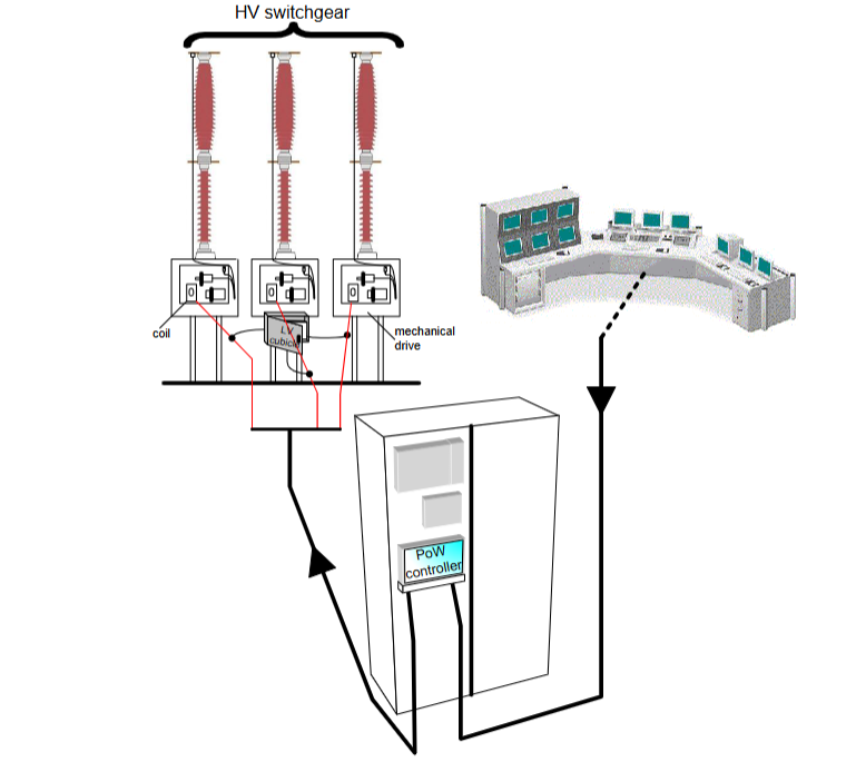
This manual is the service manual for the RPH3 "Point on Wave (PoW)" controller, which is used to guide the synchronous switching operation of high-voltage switchgear and support equipment understanding, installation, use, and maintenance.
Copyright belongs to GE Grid Solutions. The content is informative and can be adjusted according to technical and commercial needs. Unauthorized reproduction and disclosure are prohibited.
Reference architecture
GE internal documents: such as D1621EN (User Manual), D1622EN (RPH Manager Software Manual), etc.
International standard: Following IEC 62271-302 (Non synchronous pole operation of high-voltage switchgear).
Industry Report: Cited from CIGR É 262-264 publication (HVAC Switchgear Control Switching Guide).
Safety and Operation Instructions
Static Electricity and Electrical Safety
Electrostatic discharge (ESD) may damage equipment and should comply with anti-static standards such as EN 61340-5-1.
Power off before operation, confirm that the power supply voltage is compatible (AC 100-240V or DC 48-353V), only qualified engineers can operate.
Storage and installation requirements
Store in a dust-free and dry environment at -40 ℃~+70 ℃, with moisture-proof bags retained; Installed in the control room or relay room, ensuring good grounding, away from vibration sources, supporting 19 inch rack or wall mounted installation.
Principle of PoW Switching Technology
Random switching vs synchronous switching
Random switching: When the coils are powered on simultaneously, it is easy to generate surge current and overvoltage, which can cause equipment aging or protection misoperation.
PoW switching: By delaying the control of coil energization time, the high-voltage contacts are made to contact at the target point of the voltage waveform (such as zero crossing or peak), reducing transient phenomena. For example:
Inductive load (transformer) closing selects peak voltage to reduce excitation inrush current;
Capacitive load (capacitor) closing selects voltage zero crossing to reduce charging current surge.
Key parameters and terminology
Pre arming Time: The current conduction time before the mechanical contact of the contacts during closing, influenced by the dielectric strength decay rate (RDDS).
Operating Time: The time it takes for the coil to be powered on until the contacts fully move, and it is necessary to compensate for the effects of environmental temperature, hydraulic pressure, and other factors.
Adaptive Control: Based on historical operational data, adjust control timing and compensate for unpredictable factors such as equipment aging.
RPH3 Hardware and Functional Architecture
Module composition
M1: Power module, providing internal DC power supply.
M2: Central processing and communication module, integrated with DSP and Linux system, supporting Ethernet and fiber optic communication.
M3: Analog acquisition module, sampling reference voltage, current, temperature, hydraulic pressure and other signals.
M4: Signal and coil drive module, processing switch commands and relay outputs.
M5: Front panel management module, controls LED indicator lights and serial communication.
Core functional modules
Reference voltage sampling: Obtain the grid voltage through VT as a timing reference, supporting L1/L2/L3 phase selection.
Neutral point mode detection: supports hardware jumpers (M4-J5) or software settings to distinguish between grounded, isolated, or unknown modes.
Coil driver: Supports common mode/differential mode wiring, outputs 80ms adjustable pulses, and drives the opening and closing coils of switch devices.
Operation time measurement: Detect contact action through auxiliary contacts or current transformers (CT) with an accuracy of ± 0.1ms.
Compensation mechanism and adaptive control
Compensation factors for operation time
Environmental temperature: Low temperature will prolong operation time. Real time compensation can be achieved through a temperature sensor (4-20mA input), and the compensation meter can be configured through Web MMI.
Control voltage: Voltage fluctuations affect the rate of rise of coil current. The compensation value is calculated using the formula Δ t voltage=(U meas U rate − 1) ⋅ kU ⋅ t OP_rated, where kU is the compensation coefficient (to be measured).
Hydraulic pressure: For hydraulic drive mechanisms, real-time sampling is carried out through pressure sensors, and compensation is made according to Δ t pressure=(P meas P rate − 1) ⋅ kP ⋅ t OP_rated.
Idle time: Devices that have not been operated for a long time will slow down, compensated by the exponential function Δ t idle=A ⋅ (1 − e − BT idle), where A and B are empirical parameters.
Adaptive control is based on historical operational data and utilizes Δt adapt=K⋅(t measured −t commissioning −Δt compensations)+(1−K)⋅Δt adapt_prev Adjust the prediction time series, with K as the weight factor (default 0.3).
Alarm and Data Management
Alarm Type
System alarm: such as abnormal power supply, hardware failure, calibration failure, etc., triggering the red LED "3" on the front panel.
Application alarm: If the reference voltage exceeds the limit, the operation time is abnormal, the compensation value exceeds the limit, etc., the LED "4" will be triggered.
Relay output: 5 relays (1 monostable+4 bistable), which can be configured with alarm correlation logic through Web MMI.
Data recording and communication
Real time data: View parameters such as voltage, current, temperature, etc. through Web MMI, with a refresh rate of 3 seconds or 20 seconds.
Switching record: Stores the last 1025 operation data ("*. arch" file), supports downloading waveforms and event logs through RPH Manager software.
Network interface: Supports IP network (default IP 192.168.5.2), compatible with IEC 61850-9-2 communication protocol.
Application scenarios and switching strategies
Typical load switching scheme
Transformer/Three core Reactor:
Closing: Select the peak voltage (90 ° electrical angle) for the grounding neutral point, and select 0 ° or 180 ° for the isolation neutral point.
Trip: Select the current zero crossing point (corresponding to the peak voltage) to reduce overvoltage.
Single core reactor: The closing target point is the same as the transformer, and the tripping strategy is consistent.
capacitor:
Closing: Select voltage zero crossing (0 °) for the grounding neutral point and phase voltage zero crossing for the isolation neutral point.
Trip: Select the zero crossing point of the current to avoid heavy impact.
Transmission line:
Inductive VT: select voltage zero crossing for closing;
Capacitive VT: It is necessary to evaluate the residual charge in the circuit and select the peak voltage for closing.
Inductive load with NGR: Select the neutral point mode based on the inductance ratio r=LL N, and use a custom switching program when r ≥ 0.3.
Switch program configuration
Built in preset programs (transformers, reactors, capacitors), supporting user-defined modes (User Mode), can adjust the angle offset of each phase.
Technical parameters and specifications
Physical characteristics: 19 inch 4U rack, dimensions 483 × 177 × 452mm, protection level IP20.
Electrical parameters:
Power supply: AC 100-240V/50-60Hz or DC 48-353V, power consumption<20W;
Coil driving voltage: DC 33-300V, maximum current 30A (300ms).
Measurement accuracy: Voltage/current sampling error ≤ 1%, operation time measurement error ≤ ± 0.1ms.
Environmental adaptability: Operating temperature -25 ℃~+50 ℃, storage temperature -40 ℃~+70 ℃, compliant with RoHS and EMC standards (such as IEC 61000-4-2/3/5).
- YOKOGAWA
- Reliance
- ADVANCED
- SEW
- ProSoft
- WATLOW
- Kongsberg
- FANUC
- VSD
- DCS
- PLC
- man-machine
- Covid-19
- Energy and Gender
- Energy Access
- Renewable Integration
- Energy Subsidies
- Energy and Water
- Net zero emission
- Energy Security
- Critical Minerals
- A-B
- petroleum
- Mine scale
- Sewage treatment
- cement
- architecture
- Industrial information
- New energy
- Automobile market
- electricity
- Construction site
- HIMA
- ABB
- Rockwell
- Schneider Modicon
- Siemens
- xYCOM
- Yaskawa
- Woodward
- BOSCH Rexroth
- MOOG
- General Electric
- American NI
- Rolls-Royce
- CTI
- Honeywell
- EMERSON
- MAN
- GE
- TRICONEX
- Control Wave
- ALSTOM
- AMAT
- STUDER
- KONGSBERG
- MOTOROLA
- DANAHER MOTION
- Bentley
- Galil
- EATON
- MOLEX
- Triconex
- DEIF
- B&W
- ZYGO
- Aerotech
- DANFOSS
- KOLLMORGEN
- Beijer
- Endress+Hauser
- schneider
- Foxboro
- KB
- REXROTH
- YAMAHA
- Johnson
- Westinghouse
- WAGO
- TOSHIBA
- TEKTRONIX
- BENDER
- BMCM
- SMC
- HITACHI
- HIRSCHMANN
- XP POWER
- Baldor
- Meggitt
- SHINKAWA
- Other Brands
- UniOP
- KUKA
- IBA
- Beckhoff
- ADLINK
-
Beckhoff CX1100-0910 - Power Supply Module
-
Beckhoff C5210-0010 - Communication Module C5210
-
BECKHOFF KL1352 - Bus Terminal SET OF 2 FREE FAST SHIP
-
Beckhoff EL3058 - 8 x analog input single ended 4...20mA 85惟 shunt 12bit
-
Beckoff CX1100-0920 - UPS Module 24VDC (US SELLER) * *
-
BECKHOFF C6920-0000 - C69200000 PLC Moudule
-
Beckhoff CX5120-0115 - CPU controller module CX5120-0115
-
Unknown 15F5C1E-Y50A - Of Frequency Converters
-
Beckhoff AX5118-0000-0200 - Servo Drive HTP0
-
BECKHOFF AX5106-0000-0200 - Servo Drive
-
Beckhoff CX5240-0175 - Module (free) #U2327D YG
-
Beckhoff CP6607-0001-0000 - Compact PC Panel Economy Installation Operator 5,7 "
-
Beckhoff EP3744-0041 - 2022 EP37440041 Module
-
Beckhoff CP6209-0001-0020 - 6.5" PC Touch Screen Control Panel 24VDC
-
Beckhoff CX9020-0111 - /U900 +8x+2xEL3121+1x EL9410+3xEL1008+1x EL2008 Set
-
Beckhoff C6525-1030-0050 - Industrial PC
-
Beckoff CX1100-0920 - UPS Module 24VDC (US SELLER)
-
Beckhoff CX5010-0120 - CX5010 Processor Intel Atom Z510 B24
-
Siemens 6FC5203-0AF04-1BA1 - Operation Panel
-
Beckhoff CX5230-0175 - / 000029724 Embedded PC / Industrial PC on Rail
-
Beckhoff CP3916-0000 - industrielles Anzeige- und Bedienterminal
-
BECKHOFF CX1500-M310 - CX1000-N000 CX1000-0011 CX1000-C00L CX1100-0002 PLC Module
-
Beckhoff EL1872 - 16-channel digital input terminal
-
BECKHOFF EP2318-0001 - module
-
Beckhoff CX9020-0110 - Basic CPU Module
-
Beckhoff EL2564 - EtherCAT Terminal, 4-channel LED output, 5鈥?8VDC, 4A, RGBW
-
Beckhoff CX5130-0155 - /000105637 Automation Embedded PC
-
B&R 400 - Power Control Panel Rev D0 24 VDC
-
Beckhoff CX2020-0155 - module
-
Beckhoff CX9020-0115 - PLC Module
-
BECKHOFF EL6695 - PLC EL 6695
-
BECKHOFF EL7047 - PLC Modules
-
Beckhoff CX1000-0012 - Control HW 2.2 + CX1500-M310 + CX1000-C00L + CX1100-0002+
-
Beckhoff C6920-1039-0030 - control cabinet industrial PC CPU Celeron 1.90 GHz, 2 cores
-
BECKHOFF CX1100-0910 - PLC Module#
-
Beckhoff IL2301-B318-0000 - Coupler Box 4 Channel Digital Input |
-
Beckhoff CX7080 - Module
-
Beckhoff C6930-0060 - Industrial PC
-
Beckhoff CP7902-1060-0000 - Touchscreen 15 " CP7902
-
beckhoff CX9020-0111 - Controller module or UPS
-
Beckhoff CX8091 - PLC Module CX8091
-
Beckhoff C6640-1008-0030 - Control Cabinet Industrial PC
-
BECKHOFF CX1100-0920 - module
-
Beckhoff C9900-M921 - see pictures
-
BECKHOFF CP6829-0001-0000 - Touch Panel
-
BECKHOFF C6930-0060 - Industrial Computer
-
BECKHOFF CX8050 - PLC module
-
Beckhoff CP6202-0021-0020 - Touch Screen #
-
BECKHOFF AM3031-0C20-0000 - SERVO MOTOR
-
Unknown BCH1302N11A1C - Servo motor
-
Beckhoff EL2502 - 2-channel pulse width output terminal
-
Beckhoff EL6731 - Profibus Master / *Rev: 0025
-
Beckhoff CP3918-0010 - Control Panel
-
BECKHOFF CP2915-0010 - [24 MONTH WARRANTY] Control Panel
-
Beckhoff AX5203-0000-0202 - Servo Drive
-
Schneider TSXDSY64T2K - PLC OUTPUT MODULE
-
Beckhoff EP4174-0002 - Module-
-
Beckhoff IL2302-B318-0000 - Profibus Box
-
Beckhoff CP6709-0001-0000 - Touchpanel
-
BECKHOFF CX2030-0123 - Controller
-
Beckhoff CX9020-0111 - Processor Module
-
Beckhoff CX1020-0000 - CX Basic CPU Module
-
Beckhoff AX2003-AS - Servo Drive HTP0
-
Beckhoff C6240-1052-0040 - 4-086-06-3073 Industrial Computer CB1052-0003
-
Beckhoff EL1918 - 8 xTwinSAFE Input
-
Beckhoff AM8072-0R20-0000 - Servomotor
-
BECKHOFF AM8021-1B21-0000 - servo motor #T882 YS
-
Beckhoff EL6224 - 4 X Terminal IO-LINK
-
Beckhoff CX5140-0135 - embedded PC with Intel Atom processor 4 GB HW 3.6
-
Beckhoff CP7201-1000-0000 - Panel PC #
-
Beckhoff CX5130-0121 - Embedded-PC 4GB CPU Module HW 2.5 Industrial PC
-
Beckhoff AM8022-0D41-1002 - Servomotor
-
BECKHOFF CX2030-0130 - Module
-
BECKHOFF EL1872 - 16-channel digital input terminal
-
Unknown GXMMW.A203P33 - 1pc encoder
-
Beckhoff EL6631-0000 - EtherCAT Terminal 2-Port EL 6631
-
BECKHOFF C6925-0030 - Industrial Computer
-
Beckhoff CX8190 - A Module
-
BECKHOFF CX2040-0135 - CX2040-0135/000000927 CPU BASE MODULE i7 2715QE 2.1GHz --
-
BECKHOFF KL6023-0000 - Wireless adapter
-
Saia Burgess PCD7.F700 - PCD7F700 Communication Module
-
Beckhoff CX5130-0112 - CPU Module
-
BECKHOFF CX1020-N010 - CX1020-N000 CX1020-0111 CX1100-0004 EL2008 EL3064 EL4004
-
Beckhoff EP1819-0021 - A Module
-
Beckhoff CX2030-0120 - / 4gb with CX2100 0004
-
B&R X20-XC-0292 - Automation Powerlink Ethernet Bus Controller Module
-
Beckhoff BK3110 - One PLC Module
-
BECKHOFF KL3222 - PLC Module
-
BECKHOFF CX1500-M310 - CX1000-N000 CX1000-0011 CX1000-C00L CX1100-0002 PLC MODULE
-
Beckhoff CP3918-0010 - Control Panel
-
Beckhoff CX2030-0100-1002 - /4GB + CX2100 + CX2550 + CX2500-0060 + SSD
-
Beckhoff EP1816-0008 - PLC Module
-
Beckhoff CX5130-0112 - Module
-
Beckhoff Cx1500-m750 - CPU Hw: 1.4
-
BECKHOFF AX5112-0000-0200 - AX511200000200 Servo Driver
-
Beckhoff EL3751 - EtherCAT Terminal 1 Channel Analog Input Multifunction 24 Bit
-
Beckhoff CX1100-0002 - Power Supply Module
-
Beckhoff CP3916-1016-0010 - Control Panel
-
BECKHOFF CX9001-1101 - #NAME?
-
Beckhoff EP3174-0002 - EtherCAT Box Module
-
Beckhoff C6030-0070 - servo drive
-
Beckhoff CX2020-0120 - /4GB CPU, CX2100-0904, 3x EL6900, EL1904, 16GB Memory
-
BECKHOFF C6110 - BOX-PC 113608
-
BECKHOFF EK1914 - module #P
-
Beckhoff C6140 - Ipox IP-4GVI63 + CH7009A_DVI_TV + SIEMENS A5E00369843 + WD800AAJB
-
Beckhoff CX5020-0111 - controller Good quality
-
BECKHOFF C6015-0010 - / 6559380 ULTRA-COMPACT INDUSTRIAL PC ()
-
Beckhoff AX5203-0000-0200 - PLC module
-
Beckhoff EL2872 - 16-channel digital output terminal
-
BECKHOFF C3640-0000 - Panel Industrial PC 100/240VAC 128MB E0122L
-
Beckhoff CX8031 - Module
-
Beckhoff CX5020-0120-1002 - PLC module#
-
Beckhoff C6140 - M845B + SIEMENS A5E00369843 + C9900_A159_1 + AUTOMATA CAN PCI 1N
-
BECKHOFF AX5112-0000-0200 - Servo Drive*ie
-
B&R ECPA42-01 - Analog Output Module 4-Channel, +/- 10V Output Signal, 20mA Max
-
Beckhoff EL6631-0010 - PLC Module
-
BECKHOFF C6930-0070 - CONTROL CABINET INDUSTRIAL PC
-
BECKHOFF AX5112-0000-0200 - AX511200000200 Servo Driver
-
BECKHOFF EK9000 - Programmable Logic Controller Module EK9000 EK9000
-
BECKHOFF C6920-1028-0000 - Industrial computer
-
Beckhoff CX2030-0120 - controller Module
-
Beckhoff BX8000-0000 - Bus Terminal Controller HW 4.4
-
B&R 3NC154.60-2 - Positioning Module#
-
BECKHOFF CX1020-0122 - PLC module
-
Beckhoff AM3032-0D40-0000 - Servo Motor
-
BECKHOFF CX5020-0111 - CPU Module CX5020-0111
-
Beckhoff CB1051 - G5 Motherboard
-
BECKHOFF KL2641 - 1-channel relay output terminal

K-JIANG

Add: Jimei North Road, Jimei District, Xiamen, Fujian, China
Tell:+86-15305925923