
K-WANG


Siemens SINAMICS A10 Servo Drive System Operating Instructions
Siemens SINAMICS A10 Servo Drive System Operating Instructions
The servo drive system composed of Siemens SINAMICS A10 servo drive and SIMOTICS S-1FK2 servo motor covers core contents such as system composition, safety specifications, installation and wiring, configuration and debugging (supporting network servers/Startdrive), safety functions (Basic/Extended), diagnosis and maintenance, technical data, etc. It supports PROFINET/PROFIsafe communication, has high dynamic performance, compact design, flexible expansion and other characteristics, and is suitable for industrial automation scenarios such as robots, packaging machinery, printing machines, etc.
System Overview
1. System composition and core parameters
Component category, key specifications, core characteristics
Driver (A10) single-phase 230V (0.1~0.75kW), three-phase 400V (0.4~7kW) protection level IP20, supports common DC bus (up to 6 units), integrated braking resistor
Motor (1FK2) torque 0.16~40Nm, maximum speed 7400rpm permanent magnet synchronous motor, self cooling, bearing life 25000 hours
Connecting cable MOTION-CONNECT 500/800PLUS single cable integrated power/encoder/brake, small bending radius
Basic (STO/SS1/SBC) and Extended (11 functions) safety features comply with SIL 2/PL d and support PROFIsafe control
2. Core advantages
High dynamic performance: High dynamic motors have strong acceleration capabilities and are suitable for scenarios with low load inertia; Compact motors have high positioning accuracy and are suitable for variable loads.
Convenient debugging: Supports network servers (default IP: 169.254.11.22) and Startdrive software, providing one click optimization function and simplifying parameter configuration.
Safe and reliable: integrates two types of safety functions, supports fault safe digital input (F-DI) and PROFIsafe communication, and meets industrial safety standards.
Flexible Expansion: Supports common DC bus and input cascading, batch debugging can be achieved through storage cards, and is suitable for multi axis applications.
Safety regulations and installation requirements
1. Basic safety instructions
Operation permission: Only qualified professionals are allowed to operate, and the power-off discharge process must be followed (wait for 5 minutes after power-off).
Risk prevention: Avoid the impact of electromagnetic fields on medical implants (maintain a distance of ≥ 3m), and prevent electrostatic damage (wear anti-static equipment).
Environmental restrictions: Ventilation distance ≥ 100mm (up and down of the driver), prohibited from use in condensation and conductive pollution environments.
2. Installation and wiring
(1) Installation specifications
Motor installation: Use screws of grade 8.8 or above, with a tightening torque of 2.2-60Nm (depending on the motor model), to avoid impacting the shaft extension.
Driver installation: Vertical installation (LED facing up), with a distance of ≥ 10mm (side) and ≥ 100mm (up and down) from other devices.
Cable requirements: The maximum length of motor cable is 250m (with external filter), the maximum length of PROFINET cable is 100m, and both ends of the shielding layer are grounded.
(2) Key points of wiring
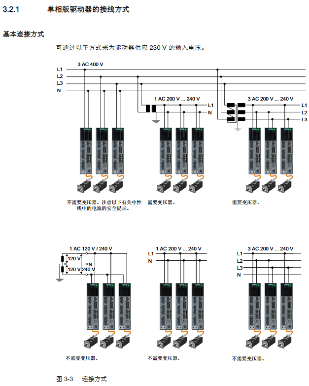
Power wiring: single-phase version is connected to L1/N, three-phase version is connected to L1/L2/L3, and a fuse (30A J level) is required.
Motor wiring: Connect U/V/W through OCC cable, and integrate the encoder and brake into the same cable.
Braking resistor: Internal braking resistor is standard, while external braking resistor needs to be matched with resistance value (150-30 Ω) and power (50-3250W).
Communication wiring: PROFINET interface X150 P1/P2, supports RJ45 FastConnect.
Configuration and Debugging
1. Debugging tools and processes
Debugging method is applicable to the core functions of the scenario
Network server local/remote debugging parameter configuration, one click optimization, security function debugging, fault diagnosis
Startdrive complex system integration hardware configuration, firmware updates, batch parameter import
Batch debugging and parameter backup/recovery of storage cards, supporting fast replication of configurations across multiple drives
2. Key debugging steps
Initial setup: Set the Administrator password (≥ 8 characters, including uppercase and lowercase letters/numbers/special characters), and configure the driver name.
One click optimization (OBT): Select dynamic characteristics (conservative/standard/dynamic), set rotation angle (recommended ≥ 360 °), optimize speed controller parameters.
Security function configuration: Select the control mode (PROFINET/onboard terminal), set parameters such as SS1 delay time and SLS speed limit.
Batch debugging: Save the configuration through a storage card or backup the parameter file (Backup. zip) on the network, and import it in batches to other drives.
3. Details of Security Features
(1) Basic Functions (standard)
STO (Safe Torque Off): Compliant with EN 60204-1 stop category 0, cutting off motor torque to prevent accidental restart.
SS1 (Safe Stop 1): Time controlled shutdown, triggering STO after delay, supporting OFF3 slope braking or external stop.
SBC (Safe Brake Control): controls the motor brake to prevent the hanging load from sagging, and needs to be used in conjunction with STO.
(2) Extended Functions (license required)
Includes STO/SS1/SBC enhanced version, with 11 new features including SS2 (Safe Shutdown 2), SOS (Safe Operation Stop), SLS (Safe Speed Limit), etc.
Support speed/acceleration/direction monitoring, controlled through PROFIsafe message 901, with a trial period of 3 segments x 300 hours.
Diagnosis and maintenance
1. Fault diagnosis
Status display: Three digit display+RDY/COMLED (green constant light=ready, red flashing=fault).
Fault response: After eliminating the cause, respond by pressing the OK button, restarting the network server, or turning off the power.
Common faults: DC bus overvoltage (F30002), brake resistor overload, PROFINET communication failure.
2. Maintenance points
Maintenance project cycle/condition operation instructions
Replace the motor bearings directly when the shaft height is ≤ AH50 after 25000 operating hours, and replace the bearings separately when the shaft height is ≥ AH63
Support network server (HTTPS) or storage card upgrade when a version update is required for firmware upgrade of the drive
After parameter backup and debugging are completed, backup the network to a file or storage card, including the Administrator password
Fan replacement is only required for the three-phase version driver after 40000 operating hours. Please refer to the spare parts order number for replacement
3. Restore factory settings
Scenario: Forgetting password, changing motor, parameter confusion.
Operation: Import the updater.inf file from the storage card, power off and restart to restore, and re debug is required.
Technical data and application scenarios
1. Key technical parameters
Environmental temperature: driver -25~70 ℃, motor -40~60 ℃ (beyond 40 ℃, capacity reduction is required).
Protection level: driver IP20, motor IP64 (with shaft sealing ring IP65).
Communication speed: PROFINET supports 10/100Mb/s and IRT synchronization.
2. Typical application scenarios
Robots and robotic arm systems: high dynamic response adapted for fast positioning.
Packaging/Plastic/Textile Machinery: Compact design saves installation space.
Wood/glass/stone processing machinery: precise positioning ensures processing accuracy.
Printing machine: synchronous control meets the requirements of high-speed printing.
- YOKOGAWA
- Reliance
- ADVANCED
- SEW
- ProSoft
- WATLOW
- Kongsberg
- FANUC
- VSD
- DCS
- PLC
- man-machine
- Covid-19
- Energy and Gender
- Energy Access
- Renewable Integration
- Energy Subsidies
- Energy and Water
- Net zero emission
- Energy Security
- Critical Minerals
- A-B
- petroleum
- Mine scale
- Sewage treatment
- cement
- architecture
- Industrial information
- New energy
- Automobile market
- electricity
- Construction site
- HIMA
- ABB
- Rockwell
- Schneider Modicon
- Siemens
- xYCOM
- Yaskawa
- Woodward
- BOSCH Rexroth
- MOOG
- General Electric
- American NI
- Rolls-Royce
- CTI
- Honeywell
- EMERSON
- MAN
- GE
- TRICONEX
- Control Wave
- ALSTOM
- AMAT
- STUDER
- KONGSBERG
- MOTOROLA
- DANAHER MOTION
- Bentley
- Galil
- EATON
- MOLEX
- Triconex
- DEIF
- B&W
- ZYGO
- Aerotech
- DANFOSS
- KOLLMORGEN
- Beijer
- Endress+Hauser
- schneider
- Foxboro
- KB
- REXROTH
- YAMAHA
- Johnson
- Westinghouse
- WAGO
- TOSHIBA
- TEKTRONIX
- BENDER
- BMCM
- SMC
- HITACHI
- HIRSCHMANN
- XP POWER
- Baldor
- Meggitt
- SHINKAWA
- Other Brands
- UniOP
- KUKA
- IBA
- Beckhoff
-
LTI SC52.0040.0012.0000.0 - Servo Drive
-
Lti SC52.0040.0012.0000.0 - Servo Drive
-
Milton Industries LTI Tool By Milton LT1240 - 1/2" Drive Lugnut Remover
-
LTi Drives SO84.200.P030.0000.0-W - Servo Spindle Drive
-
LTI DRIVES LSP08-035-320-30-B0R1PY170 - Servo Motor
-
LTI DRIVES SE84.200.SC00.0001.0-W - Servo Drive
-
Lust CDE34.005.W2.2 - Lti Drives Controller
-
LTi SO84.012.0030.0011.2 - ServoOne Servo Drive
-
LTi Drives SO CM-P.0010.11.00.0 - Servo Drive Controller
-
LTi CDE34.017.W3.0 - Servo Drive
-
LTI Drives CDB32.004, C2.0,SH - Positioning Controller
-
LUST CM-CAN1 - LTi DRIVES Communication Module
-
LTi SO84.012.1030.0000.2 - Servo Drive
-
LTI MOOG CDE54.044 - PITCHMASTER FREQUENCY CONVERTER 181-01019
-
MOOG LTI 181-01019 CDE54.044 - PITCHMASTER FREQUENCY CONVERTER
-
Lust LTi Drives CDE34.010,D2.0 - Servo Drive Controller
-
LTI SO84.032.0003.0101.2 - Servo Drive
-
Seagate 9CC132-302 Harris LTI-CS IRT-34-0021-01 - Hard Drive 160GB
-
LTI SO84.032.0003.0001.2 - Servo Drive
-
LTI SO24.007.0070.0000.1 - SERVO CONTROLLER
-
LTi drive CDA32.003.C3.0.H05-01.PC1 - Servo Drive
-
LTI SO84.016.0030.0000.2 - SERVO CONTROLLER
-
LUST LTI CD A34.008,W1.4, BR - SERVO DRIVE
-
MOOG LTI 181-01019 CDE54.044 - PITCHMASTER FREQUENCY CONVERTER
-
LTI MOOG 181-01019 - PITCH Master Servo Drive CDE54.044
-
LTI SERVO ONE SO84.045.0030.0001.2-W - Drive
-
LUST LTi SO84.032.0040.0000.2 - SERVO ONE DRIVE
-
LTi Drives LSH-074-2-30-3 20/T1,G6.1M - SERVO MOTOR
-
LTI SO84.016.0000.0101.2 - servo drive
-
LTI SA54.0550.0033.0000.0 - Servo Drive
-
LTI SA54.0550.0033.0000.0 - Servo Drive
-
LTI LT 4850 - 3/8" Drive 3-Pc Twist Socket Transmission Drain Plug Removal System
-
LTI Tools LT4400-30 Lock Technology - 3/4" Twist Socket 1/2" Drive Lugnut Remover
-
LTI Tools LT-1400C - 1/2 Drive Wheel Torque Extension Tool
-
LTI Tools LT1250 - 1/2" Drive Dual Sided Socket Lug Nut Remover Tool
-
LTI SO84.032.0003.0101.2 - Servo Drive
-
LTI MOOG 181-01019 - PITCH Master Servo Drive CDE54.044
-
MOOG LTI 181-01019 CDE54.044 - PITCHMASTER FREQUENCY CONVERTER
-
MOOG LTI 181-01019 CDE54.044 - PITCHMASTER FREQUENCY CONVERTER
-
MOOG LTI 181-01019 CDE54.044 - PITCHMASTER FREQUENCY CONVERTER
-
LTI SA54.0550.0033.0000.0 - Servo Drive
-
LTI Tools LT-4800 - 7 Piece Twist Socket 3/8" Drive Oil Drain Plug Removal Set
-
LTI SA54.0550.0033.0000.0 - Servo Drive
-
LTI Drive SO24.007.00300000.0 - Servo Drive
-
LTI TOOLS LTI 1400-I - Drive Wheel Torque Extension
-
LTI Tools LT4400-3 - 3/4" 19mm Twist Socket 1/2" Drive Lugnut
-
LTI TOOLS LTI 1400-BB - Drive Wheel Torque Extension
-
LTI SO84.032.0003.0101.2 - Servo Drive
-
LTI Tools LT-4512 - 3/8" Drive 12mm Twist Socket
-
LTI MOTION Luster SO84.032.0003.0001.2 - Servo Drive
-
LTI Tool By Milton LT1600P - 1" Drive Torx Stick
-
LTI Lust VF1424L,HF,OP2,S56 - Variable Frequency Drive
-
LUST CDA32.004,C1.4,H08,B0 - SERVO DFRIVE CM-CAN1 Module
-
LTI SO84.045.0002.0001.2-W - Drive
-
LTI Lust VF1404M,C9,PT1,BR1 - Inverter Type VF1404M
-
LTI SA54.0550.0033.0000.0 - Servo Drive
-
LTI Tools LT-1400C - 1/2" Drive Wheel Torque Extension
-
Lust LTI DRiVES CDA32.006, C3.0, H09 - Variateur De Fr茅quence Frequency Inverter
-
LTI MOOG CDE54.044 - PITCH master SERVO DRIVE
-
LTI MOOG CDE54.044 - PITCH master SERVO DRIVE
-
LTI SO84.143.0020.0101.2-W - servo drive
-
LTI MOTION SC34.0200.0011.0000.0 - Servo drives
-
LTI SO84.032.0003.0001.2 - Servo Drive
-
LTI DRIVES GmbH MS100 - Assembly Set Mounting Kit
-
LTI SO84.032.0003.0001.2 - Servo Drive
-
LTI SO84.032.0003.0001.2 - Servo Drive
-
LTI MOTION SO84.032.0003.0101.2 - servo drive
-
LTI SO84.032.0003.0101.2 - Servo Drive
-
LTI MOOG CDE54.044 - PITCH master SERVO DRIVE
-
LTI MOTION CDE32.004.C2.4 - Servo drives
-
LTI CDD34.032锛學x.x锛孊R锛孭C1 - Servo Drive
-
Lust LTI DRiVES CDA32.006, C3.0, H09 - Inversor De Frecuencia Frequency Inverter
-
Lust SO84.008.0030.1000.0 - Servo One LTi Drive
-
LTI MOTION SO84.032.0003.0101.2 - Servo drives
-
LUST LTi CDA32.004,C1.4 - SERVO DRIVE
-
LTI MOOG CDE54.044 - PITCH Master SERVO DRIVE
-
LTI KEBA CDB32.004 C2.7, SH - PN: 08673530 Frequency Inverter
-
LTI Tools LT-1400C - 1/2" Drive Wheel Torque Extension
-
LTI LT1400-E - 1/2" Drive Wheel Torque Extension
-
LTI MOOG 181-01019 - PITCH master SERVO DRIVE CDE54.044
-
LTI LSN-097-0510-30-560/T1 - Actuator Motor
-
LTI Tools LT 4800 - 7 Piece 3/8" Drive Twist Socket Oil Drain Plug Removal System
-
LTI DRIVES GmbH MS100 - MONTAGESET Assembly Set Mounting Kit
-
Lti SC52.0040.0012.0000.0 - Servo Drive
-
LTI DRIVES GmbH MS100 - Juego De Montaje Assembly Set Mounting Kit
-
LTi DSM4-14.2-21R83-200 - Drives servomoteur Servo Motor
-
MOOG CDE 54.044.GDA - Pitch Master Industrielle Turbine Lti Drive
-
LTI SO24.004.0030.1000.0 - Servo Drive Controller
-
Lti MOOG CDE54.044 - Pitch Master Servo Drive
-
Lust LTI DRiVES CDA32.006, C3.0, H09 - Inverter
-
LTI MOTION GMBH CDB34.006,W3.0,PC1,H39 - Frequency inverter
-
LTI SO84.032.0003.0001.2 - Servo Drive
-
MOOG CDE 54.044.D - Pitch Master Industrielle Turbine Lti Drive
-
LTI TOOLS LT-1460 - 1/2" DRIVE WHEEL TORQUE EXTENSION KIT 5 PIECE SET
-
Lust Cdb32.003, C2.4 - Lti Drives Servoregulador Frecuencia Servo Controller Inverter
-
Lust LTI DRIVES CDA32.006, C3.0, H09 - Frequency Inverter
-
Lust Lti SO82.004.0030.0000.2 - Servo Drive
-
LTI MOTION SC34.0200.0011.0000.0-SL - Servo drives
-
LTI MOTION SA54.0075.0033.0000.0 - Servo drives
-
LTI MOTION SC32.0075.1011.0000.0 - Servo drives
-
LTI Servo-One Junior SO22.006.0080.1000.0 - Servo Controller Servoregler
-
LUST CDA32.004, C1.4, H08, B0 - Servo Drive & LTI CM-CAN1 Module
-
LTI DRIVES LSP08-035-320-30-B0R1PY170 - Servo Motor
-
LUST LTI CDA32.004,C1.4.H08.B0 - SERVO CONTROLLER DRIVES
-
LUST LTi DRiVES CDS44.072LC1.2 - Servo Drive
-
Lti Servo-One Junior SO22.006.0082.1000.0 - Servo Controller Servoregler
-
LUST CDA32.008,C2.0,HF - Lti DRIVES Spindle Drive Inverter
-
LTI SO22.003.0082.0000.0 - Servo Drives One junior Servo Controller Servoregler
-
Lust Lti Drives CM-CAN1 - Communication Module
-
LUST Lti Drives Vf1202s, G8, I6 - Frequency Inverter Drive
-
LTI DRIVES BR-090.03.540.UR.H38 - Bremswiderstand Brake Resistor
-
LTi DRIVES PM-E40.2DRA054P - Wind Turbine Pitch Control Inverter
-
LTi Drives GmbH br-110.01.540-UR - Brake Resistor
-
LTI Drives LSN-097-0960-30-0560/T1,S4,B - Servo Motor
-
LUST CDA34.006.C2.0 - LTI Drives Servoregler
-
LUST LTI DRIVES SERVO ONE JUNIOR SO24.002.0020.0000.1 - Servo Drive Controller
-
LTI MOTION SO84.032.0003.0001.2 - Servo drives
-
LTI DDTD750V2-120 - IBOP ACTUATOR CYLINDER FOR TOP DRIVE
-
LTI CDE32.004, C2.4 - SERVO DRIVE
-
LUST LTI DRIVES CDD34.017 W3.4PC1 - Servo Drive Controller
-
LTI CDA3208,C3,0,HF - AC SERVO DRIVE
-
LUST LTI DRIVES LSH-074-3-30-560/T1,G6.1S - SERVO MOTOR
-
LUST Lti CDB32.004.C2.4.SH - AC Servo Drive
-
LTi CDA32.006, C3.0, H09 - Servo Drive
-
LTI SO22.003.0010.0000.0 - Servo Drive Servo one junior Servoregler Controller
-
LTi Drives DSM4-14.2-21R83-200 - Servo Motor
-
LUST Lti Drives Lsh-097-1-30-560/T1, 1R - Servomotor
-
LTI 1237 - 7 Piece 1/2" Drive Flip Socket Set

K-JIANG

Add: Jimei North Road, Jimei District, Xiamen, Fujian, China
Tell:+86-15305925923