
K-WANG


SINUMERIK System 800 General Interface Planning Guide
SINUMERIK System 800 General Interface Planning Guide
The SINUMERIK System 800 Universal Interface Planning Guide (December 1995 edition) is a technical document aimed at machine tool manufacturers, supporting multiple series of control systems such as SINUMERIK 805/810/820/840/850/880. The core content covers the technical specifications of V.24 (RS232C), 20 mA current loop, and RS 422 serial interfaces (signal definition, level polarity, drive receiving module), interface adaptation (pin allocation, transmission format setting), data transmission timing (line control/character control equipment), interface configuration of various models of control systems, as well as practical connection schemes (cable models, parameter settings, wiring diagrams) for more than 30 types of I/O devices such as printers, tape drives, and programmers. It also clarifies different types of I/O devices. The maximum transmission distance of the interface, electromagnetic compatibility requirements, and equipment adaptation principles.
Three core interface technical specifications
2.1 V.24 (RS232C) interface
Signal definition: Following DIN 66020/CCITT V.24/V.28 standard, including data line (D1=TxD, D2=RxD), control line (S2=RTS, S1.2=DTR), message line (M1=DSR, M2=CTS), grounding line (E1=protective ground, E2=signal ground).
Level and polarity: The logic L of the data/control signal is+3~+15V, the logic H is -3~-15V, the signal reference ground is E2, and the transition interval (± 3V) state is undefined.
Drive and receive modules: Drive module 75188 (power supply ± 15V, maximum output current 10mA), receive module 75189 (maximum input voltage ± 30V, input resistance 390 Ω).
Transmission restriction: The maximum cable length is 30m and cannot be connected simultaneously with a 20mA interface.
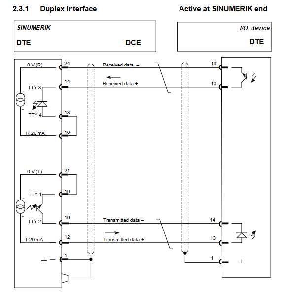
2.2 20 mA current loop interface
Signal characteristics: transmitted as a current signal, with logic L corresponding to 20mA (± 30%), logic H corresponding to 0-2mA, and SINUMERIK providing a 12V current source.
Working mode: Duplex dual line pair, supporting SINUMERIK active (providing current)/passive (external device providing current) mode, switched through cable pin allocation.
Device connection: It is necessary to distinguish between active/passive mode wiring, and verify the 20mA current value when closing the circuit, which is equivalent to the V.24 signal function (TxD=TTY2, RxD=TTY4, etc.).
Transmission limit: Maximum cable length of 1km.
2.3 RS 422 interface
Core advantage: Combining the modulation and demodulation control capability of V.24 with the long-distance transmission advantage of 20mA, adopting dual line differential transmission.
Level specification: Drive output VoL ≤ 0.5V, VoH ≥ 2.5V, differential voltage 2~5V, reference AM26 LS 31/33 module voltage.
Drive and receive: AM26 LS 31 drive module (powered by 5V), AM26 LS 33 receive module (input parallel resistance of 150 Ω).
Extension function: Supports level conversion from V.24 to RS 422 (dedicated cable integrated converter), with a maximum transmission distance of 1km.
Interface adaptation and configuration
3.1 Pin allocation
Interface type, connector specifications, key pin functions
V. 24/20mA universal 25 pin D-Sub socket V.24:2=* TxD, 3=* RxD, 4=RTS, 5=CTS; 20mA:10=TTY2、12=T 20mA、13=TTY4
RS 422 25 pin D-Sub socket 2=* TxD, 3=* RxD, 4=RTS, 5=CTS, 15=TxD, 16=RxD
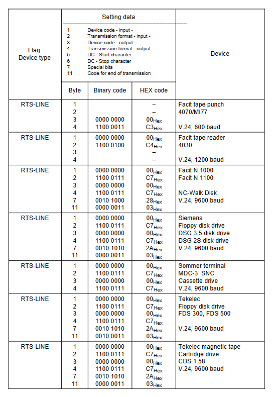
3.2 Transmission Format Settings
Core parameters: 15 byte set data, including device encoding (line control/character control/dedicated equipment), transmission format (baud rate 110~9600 baud, parity (presence/absence/parity), stop bits (1/1.5/2)).
Special configuration: Xon/Xoff character definition, EIA code special character substitution (@/:/=, etc.), transmission termination character setting.
Adaptation principle: Line control equipment relies on DSR/DTR/CTS/RTS lines, character control equipment relies on Xon/Xoff characters, and uncontrolled equipment adopts asynchronous transmission.
3.3 Data transmission timing sequence
Line control equipment: When inputting, NC confirms equipment readiness through DTR/DSR, and RTS controls data reception; When outputting, NC confirms that the device buffer is idle through CTS, and the transmission terminates at ETX or program end.
Character control device: When inputting, NC sends Xon to allow data transmission, Xoff pauses; When outputting, NC starts transmission after receiving Xon, and supports direct startup without first Xon (set byte 7 bit 7).
Key time limit: timeout monitoring defaults to 60 seconds (can be turned off) to avoid transmission lag.
Interface configuration of each control system
Control system model, interface quantity, interface type, special instructions
SINUMERIK 805 1 standard+1 optional standard V.24/20mA, optional V.24 (supports RS422 conversion) 25 pin D-Sub socket
SINUMERIK 810 GA3/820 GA3 1 standard+1 optional standard V.24/20mA, optional V.24 (supports RS422 conversion) operation panel front and rear interface
SINUMERIK 840 1 standard+1 optional standard V.24/20mA, optional V.24 (supports RS422 conversion) machine control panel front-end interface
SINUMERIK 850 supports up to 4 V.24/20mA/RS422 central controllers+operation panel interfaces
SINUMERIK 880 supports up to 4 V.24/20mA/RS422 slot configurations to distinguish different models
Practical Connection Scheme for I/O Devices
5.1 Equipment Classification and Adaptation List
Covering over 30 types of devices, the core categories include:
Printing equipment: Siemens PT 80/PT 88 printer
Magnetic tape/floppy disk devices: SINUMERIK T30/T40/T50/T60 tape drive, Siemens DSG 3.5/2S floppy disk drive
Programming equipment: SIMATIC PG 670/675/685/750 programmer
Data carrier: GNT 7101 NC data carrier CAN NC Recorder FD/FH
Workstation: SINUMERIK WS 800/WS 800A Programming Workstation
5.2 Connection Core Parameters (Example)
Equipment Name Interface Type Baud Rate Cable Model Key Settings
Siemens PT 80 printer V.24/20mA 300 baud 6FC9 340-8C (V.24) 8 data bits, 2 stop bits
SINUMERIK T60 tape drive V.24 9600 baud 6FC9 344-2C DIP switch 8-position OFF
SIMATIC PG 750 programmer V.24 9600 baud 6FC9 344-4R even parity, 2 stop bits
RS 422 conversion from V.24 to RS422 adaptation device 6FC9 344-2VZ maximum transmission 100m
5.3 Cable and wiring requirements
Cable specification: Shielded cable (such as 8 × 2 × 0.18mm ²), with power and control lines laid separately.
Grounding requirements: The shielding layer is grounded at both ends, and the protective grounding (E1) complies with DIN VDE 0160 standard.
Ordering information: Clearly specify the cable ordering number and maximum length (mainly 30m, some up to 100m) for each type of equipment.
Key specifications and precautions
Electromagnetic compatibility: Follow VDI 2880 guidelines, cable grouping and routing to avoid interference.
Equipment adaptation: The connection between DTE equipment (SINUMERIK) and DTE equipment requires cross wiring (sending → receiving).
Encoding conversion: Missing characters (such as @/:) in EIA codes need to be replaced by setting data definitions.
Transmission restrictions: Strictly adhere to the maximum transmission distance of each interface, and use RS 422 or conversion scheme for exceeding the distance.
- YOKOGAWA
- Reliance
- ADVANCED
- SEW
- ProSoft
- WATLOW
- Kongsberg
- FANUC
- VSD
- DCS
- PLC
- man-machine
- Covid-19
- Energy and Gender
- Energy Access
- Renewable Integration
- Energy Subsidies
- Energy and Water
- Net zero emission
- Energy Security
- Critical Minerals
- A-B
- petroleum
- Mine scale
- Sewage treatment
- cement
- architecture
- Industrial information
- New energy
- Automobile market
- electricity
- Construction site
- HIMA
- ABB
- Rockwell
- Schneider Modicon
- Siemens
- xYCOM
- Yaskawa
- Woodward
- BOSCH Rexroth
- MOOG
- General Electric
- American NI
- Rolls-Royce
- CTI
- Honeywell
- EMERSON
- MAN
- GE
- TRICONEX
- Control Wave
- ALSTOM
- AMAT
- STUDER
- KONGSBERG
- MOTOROLA
- DANAHER MOTION
- Bentley
- Galil
- EATON
- MOLEX
- Triconex
- DEIF
- B&W
- ZYGO
- Aerotech
- DANFOSS
- KOLLMORGEN
- Beijer
- Endress+Hauser
- schneider
- Foxboro
- KB
- REXROTH
- YAMAHA
- Johnson
- Westinghouse
- WAGO
- TOSHIBA
- TEKTRONIX
- BENDER
- BMCM
- SMC
- HITACHI
- HIRSCHMANN
- XP POWER
- Baldor
- Meggitt
- SHINKAWA
- Other Brands
- UniOP
- KUKA
- IBA
- Beckhoff
-
LTI SC52.0040.0012.0000.0 - Servo Drive
-
Lti SC52.0040.0012.0000.0 - Servo Drive
-
Milton Industries LTI Tool By Milton LT1240 - 1/2" Drive Lugnut Remover
-
LTi Drives SO84.200.P030.0000.0-W - Servo Spindle Drive
-
LTI DRIVES LSP08-035-320-30-B0R1PY170 - Servo Motor
-
LTI DRIVES SE84.200.SC00.0001.0-W - Servo Drive
-
Lust CDE34.005.W2.2 - Lti Drives Controller
-
LTi SO84.012.0030.0011.2 - ServoOne Servo Drive
-
LTi Drives SO CM-P.0010.11.00.0 - Servo Drive Controller
-
LTi CDE34.017.W3.0 - Servo Drive
-
LTI Drives CDB32.004, C2.0,SH - Positioning Controller
-
LUST CM-CAN1 - LTi DRIVES Communication Module
-
LTi SO84.012.1030.0000.2 - Servo Drive
-
LTI MOOG CDE54.044 - PITCHMASTER FREQUENCY CONVERTER 181-01019
-
MOOG LTI 181-01019 CDE54.044 - PITCHMASTER FREQUENCY CONVERTER
-
Lust LTi Drives CDE34.010,D2.0 - Servo Drive Controller
-
LTI SO84.032.0003.0101.2 - Servo Drive
-
Seagate 9CC132-302 Harris LTI-CS IRT-34-0021-01 - Hard Drive 160GB
-
LTI SO84.032.0003.0001.2 - Servo Drive
-
LTI SO24.007.0070.0000.1 - SERVO CONTROLLER
-
LTi drive CDA32.003.C3.0.H05-01.PC1 - Servo Drive
-
LTI SO84.016.0030.0000.2 - SERVO CONTROLLER
-
LUST LTI CD A34.008,W1.4, BR - SERVO DRIVE
-
MOOG LTI 181-01019 CDE54.044 - PITCHMASTER FREQUENCY CONVERTER
-
LTI MOOG 181-01019 - PITCH Master Servo Drive CDE54.044
-
LTI SERVO ONE SO84.045.0030.0001.2-W - Drive
-
LUST LTi SO84.032.0040.0000.2 - SERVO ONE DRIVE
-
LTi Drives LSH-074-2-30-3 20/T1,G6.1M - SERVO MOTOR
-
LTI SO84.016.0000.0101.2 - servo drive
-
LTI SA54.0550.0033.0000.0 - Servo Drive
-
LTI SA54.0550.0033.0000.0 - Servo Drive
-
LTI LT 4850 - 3/8" Drive 3-Pc Twist Socket Transmission Drain Plug Removal System
-
LTI Tools LT4400-30 Lock Technology - 3/4" Twist Socket 1/2" Drive Lugnut Remover
-
LTI Tools LT-1400C - 1/2 Drive Wheel Torque Extension Tool
-
LTI Tools LT1250 - 1/2" Drive Dual Sided Socket Lug Nut Remover Tool
-
LTI SO84.032.0003.0101.2 - Servo Drive
-
LTI MOOG 181-01019 - PITCH Master Servo Drive CDE54.044
-
MOOG LTI 181-01019 CDE54.044 - PITCHMASTER FREQUENCY CONVERTER
-
MOOG LTI 181-01019 CDE54.044 - PITCHMASTER FREQUENCY CONVERTER
-
MOOG LTI 181-01019 CDE54.044 - PITCHMASTER FREQUENCY CONVERTER
-
LTI SA54.0550.0033.0000.0 - Servo Drive
-
LTI Tools LT-4800 - 7 Piece Twist Socket 3/8" Drive Oil Drain Plug Removal Set
-
LTI SA54.0550.0033.0000.0 - Servo Drive
-
LTI Drive SO24.007.00300000.0 - Servo Drive
-
LTI TOOLS LTI 1400-I - Drive Wheel Torque Extension
-
LTI Tools LT4400-3 - 3/4" 19mm Twist Socket 1/2" Drive Lugnut
-
LTI TOOLS LTI 1400-BB - Drive Wheel Torque Extension
-
LTI SO84.032.0003.0101.2 - Servo Drive
-
LTI Tools LT-4512 - 3/8" Drive 12mm Twist Socket
-
LTI MOTION Luster SO84.032.0003.0001.2 - Servo Drive
-
LTI Tool By Milton LT1600P - 1" Drive Torx Stick
-
LTI Lust VF1424L,HF,OP2,S56 - Variable Frequency Drive
-
LUST CDA32.004,C1.4,H08,B0 - SERVO DFRIVE CM-CAN1 Module
-
LTI SO84.045.0002.0001.2-W - Drive
-
LTI Lust VF1404M,C9,PT1,BR1 - Inverter Type VF1404M
-
LTI SA54.0550.0033.0000.0 - Servo Drive
-
LTI Tools LT-1400C - 1/2" Drive Wheel Torque Extension
-
Lust LTI DRiVES CDA32.006, C3.0, H09 - Variateur De Fr茅quence Frequency Inverter
-
LTI MOOG CDE54.044 - PITCH master SERVO DRIVE
-
LTI MOOG CDE54.044 - PITCH master SERVO DRIVE
-
LTI SO84.143.0020.0101.2-W - servo drive
-
LTI MOTION SC34.0200.0011.0000.0 - Servo drives
-
LTI SO84.032.0003.0001.2 - Servo Drive
-
LTI DRIVES GmbH MS100 - Assembly Set Mounting Kit
-
LTI SO84.032.0003.0001.2 - Servo Drive
-
LTI SO84.032.0003.0001.2 - Servo Drive
-
LTI MOTION SO84.032.0003.0101.2 - servo drive
-
LTI SO84.032.0003.0101.2 - Servo Drive
-
LTI MOOG CDE54.044 - PITCH master SERVO DRIVE
-
LTI MOTION CDE32.004.C2.4 - Servo drives
-
LTI CDD34.032锛學x.x锛孊R锛孭C1 - Servo Drive
-
Lust LTI DRiVES CDA32.006, C3.0, H09 - Inversor De Frecuencia Frequency Inverter
-
Lust SO84.008.0030.1000.0 - Servo One LTi Drive
-
LTI MOTION SO84.032.0003.0101.2 - Servo drives
-
LUST LTi CDA32.004,C1.4 - SERVO DRIVE
-
LTI MOOG CDE54.044 - PITCH Master SERVO DRIVE
-
LTI KEBA CDB32.004 C2.7, SH - PN: 08673530 Frequency Inverter
-
LTI Tools LT-1400C - 1/2" Drive Wheel Torque Extension
-
LTI LT1400-E - 1/2" Drive Wheel Torque Extension
-
LTI MOOG 181-01019 - PITCH master SERVO DRIVE CDE54.044
-
LTI LSN-097-0510-30-560/T1 - Actuator Motor
-
LTI Tools LT 4800 - 7 Piece 3/8" Drive Twist Socket Oil Drain Plug Removal System
-
LTI DRIVES GmbH MS100 - MONTAGESET Assembly Set Mounting Kit
-
Lti SC52.0040.0012.0000.0 - Servo Drive
-
LTI DRIVES GmbH MS100 - Juego De Montaje Assembly Set Mounting Kit
-
LTi DSM4-14.2-21R83-200 - Drives servomoteur Servo Motor
-
MOOG CDE 54.044.GDA - Pitch Master Industrielle Turbine Lti Drive
-
LTI SO24.004.0030.1000.0 - Servo Drive Controller
-
Lti MOOG CDE54.044 - Pitch Master Servo Drive
-
Lust LTI DRiVES CDA32.006, C3.0, H09 - Inverter
-
LTI MOTION GMBH CDB34.006,W3.0,PC1,H39 - Frequency inverter
-
LTI SO84.032.0003.0001.2 - Servo Drive
-
MOOG CDE 54.044.D - Pitch Master Industrielle Turbine Lti Drive
-
LTI TOOLS LT-1460 - 1/2" DRIVE WHEEL TORQUE EXTENSION KIT 5 PIECE SET
-
Lust Cdb32.003, C2.4 - Lti Drives Servoregulador Frecuencia Servo Controller Inverter
-
Lust LTI DRIVES CDA32.006, C3.0, H09 - Frequency Inverter
-
Lust Lti SO82.004.0030.0000.2 - Servo Drive
-
LTI MOTION SC34.0200.0011.0000.0-SL - Servo drives
-
LTI MOTION SA54.0075.0033.0000.0 - Servo drives
-
LTI MOTION SC32.0075.1011.0000.0 - Servo drives
-
LTI Servo-One Junior SO22.006.0080.1000.0 - Servo Controller Servoregler
-
LUST CDA32.004, C1.4, H08, B0 - Servo Drive & LTI CM-CAN1 Module
-
LTI DRIVES LSP08-035-320-30-B0R1PY170 - Servo Motor
-
LUST LTI CDA32.004,C1.4.H08.B0 - SERVO CONTROLLER DRIVES
-
LUST LTi DRiVES CDS44.072LC1.2 - Servo Drive
-
Lti Servo-One Junior SO22.006.0082.1000.0 - Servo Controller Servoregler
-
LUST CDA32.008,C2.0,HF - Lti DRIVES Spindle Drive Inverter
-
LTI SO22.003.0082.0000.0 - Servo Drives One junior Servo Controller Servoregler
-
Lust Lti Drives CM-CAN1 - Communication Module
-
LUST Lti Drives Vf1202s, G8, I6 - Frequency Inverter Drive
-
LTI DRIVES BR-090.03.540.UR.H38 - Bremswiderstand Brake Resistor
-
LTi DRIVES PM-E40.2DRA054P - Wind Turbine Pitch Control Inverter
-
LTi Drives GmbH br-110.01.540-UR - Brake Resistor
-
LTI Drives LSN-097-0960-30-0560/T1,S4,B - Servo Motor
-
LUST CDA34.006.C2.0 - LTI Drives Servoregler
-
LUST LTI DRIVES SERVO ONE JUNIOR SO24.002.0020.0000.1 - Servo Drive Controller
-
LTI MOTION SO84.032.0003.0001.2 - Servo drives
-
LTI DDTD750V2-120 - IBOP ACTUATOR CYLINDER FOR TOP DRIVE
-
LTI CDE32.004, C2.4 - SERVO DRIVE
-
LUST LTI DRIVES CDD34.017 W3.4PC1 - Servo Drive Controller
-
LTI CDA3208,C3,0,HF - AC SERVO DRIVE
-
LUST LTI DRIVES LSH-074-3-30-560/T1,G6.1S - SERVO MOTOR
-
LUST Lti CDB32.004.C2.4.SH - AC Servo Drive
-
LTi CDA32.006, C3.0, H09 - Servo Drive
-
LTI SO22.003.0010.0000.0 - Servo Drive Servo one junior Servoregler Controller
-
LTi Drives DSM4-14.2-21R83-200 - Servo Motor
-
LUST Lti Drives Lsh-097-1-30-560/T1, 1R - Servomotor
-
LTI 1237 - 7 Piece 1/2" Drive Flip Socket Set

K-JIANG

Add: Jimei North Road, Jimei District, Xiamen, Fujian, China
Tell:+86-15305925923