
K-WANG


SIEMIENS SIPART PS2 (6DR5...) Electrical Positioner Operation Guide
SIEMIENS SIPART PS2 (6DR5...) Electrical Positioner Operation Guide
Basic and Product Overview
Overview
The compact operation guide for SIPART PS2 (6DR5...) electric pneumatic positioner covers core contents such as product introduction, safety instructions, installation and mounting, connection, debugging, maintenance, technical parameters, and appendices. It is clear that the positioner is suitable for continuous control of process valves in multiple industries such as chemical, oil and gas, and energy. It emphasizes that the use in hazardous areas must comply with explosion-proof standards (such as ATEX, IECEx), and installation and debugging must follow specific steps (such as automatic/manual initialization). At the same time, detailed technical data (such as working temperature -30~+80 ° C, protection level IP66) and adaptation information for each module (alarm, position feedback, etc.) are provided to ensure safe and compliant operation of the equipment.
Product Usage and Compatibility
Usage: Used in 8 major industries including chemical, oil and gas, energy, food and beverage, papermaking, water supply and drainage, pharmaceuticals, and offshore platforms to achieve continuous control of valves in pneumatic drive processes
Compatibility: Different document versions need to match specific device firmware (FW) and integrated software versions, as shown in the table below:
Communication protocol document version, device firmware requirements, compatible with integrated software (including EDD version)
HART 05/2018 FW: 5.01.00 and above; Device version 6 and above SIMATIC PDM V9.0(EDD:23.00.00+)、AMS Device Manager V12.5(EDD:23.00.00+) wait
PROFIBUS PA 05/2018 FW: 6.00.00 and above SIMATIC PDM V9.0 (EDD: 22.00.00+), SITRANS DTM V4.1 (EDD: 22.00.01+), etc
FOUNDATION Fieldbus 05/2018 FW: 3.00.00 and above; Device version 3 SITRANS DTM V4.1(EDD:3.00.00+)、AMS Device Manager V12.5(EDD:3.00.00+) wait
Goods inspection and nameplate
Goods inspection: After receiving the goods, it is necessary to check whether the packaging/items are damaged and verify the consistency between the order and the shipping documents; Prohibit the use of damaged or incomplete equipment (there is a risk of explosion in hazardous areas)
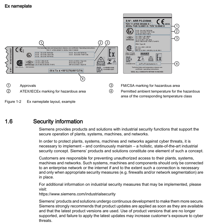
Nameplate information: including key information such as manufacturer, protection level (e.g. IP66), software and hardware versions, explosion-proof identification (e.g. Ex d IIC T6/T4), serial number, etc. The explosion-proof nameplate needs to be additionally labeled with ATEX/IECEx/FM/CSA certification information
Safety instructions (core risk prevention and control)
Warning level system
DANGER: Failure to take preventive measures may result in death or serious personal injury
Warning: Failure to take preventive measures may result in death or serious personal injury
CAUTION: Failure to take preventive measures may result in minor personal injury
NOTICE: Failure to take preventive measures may result in property damage
Requirements for use in hazardous areas
Operator: Must have the qualification to operate equipment in hazardous areas and be familiar with electrical, high-voltage, and hazardous medium safety regulations
Explosion proof requirements: Only use equipment labeled with the corresponding explosion-proof level (such as II 2 G Ex d IIC T6/T4 Gb), and prohibit the use of equipment suitable for non hazardous areas; If the equipment has been used in non hazardous areas, its explosion-proof label must be permanently removed
Special Warning: The pneumatic terminal board of 6DR5. 6 locator is a safety component of explosion-proof shell, and its fixing screws must not be loosened
Other safety regulations
Equipment modification: Only modifications are allowed according to the document instructions. Unauthorized modifications will cancel the warranty and certification
Power requirements: It is necessary to connect a safety isolated Extra Low Voltage (SELV) to avoid voltage flashover; Dangerous area connection equipment must be carried out in a power-off state (except for Ex i version)
Cable requirements: Use cable glands/plugs that meet explosion-proof standards. Unused cable entrances must be sealed, and shielded cables are only allowed to be grounded at one end (when crossing hazardous areas)
Installation and mounting
Basic security prerequisites
Pneumatic actuators have high operating force and must follow their safety instructions; The mounting kit with position detection lever poses a risk of compression, and it is prohibited to insert limbs into the range of motion of the lever
Only use Siemens original accessories/spare parts to avoid the risk of explosion in hazardous areas; Before installation, confirm that there is no visible damage to the equipment and that the sealing gasket is correctly positioned to avoid damage during cover installation
Different mounting methods for actuators
Linear actuator: Use 6DR4004-8V mounting kit, suitable for stroke 3-35mm; for stroke exceeding 35mm, an additional 6DR4004-8L lever needs to be ordered
Angular stroke actuator: VDI/VDE 3845 mounting surface (thickness>4mm with reinforcement) needs to be provided on the actuator side, paired with 6DR4004-8D kit or TGX: 16300-1556 stainless steel coupling
Vibration/acceleration environment treatment
The equipment is equipped with a friction clutch and a gear lock with a transmission ratio selector to cope with strong vibrations/accelerations (such as emergency shut-off valves, steam shock scenarios)
Locking steps: Ensure that the gear lock is in the neutral position → Confirm the gear ratio selector (33 ° or 90 °) → Lock the gear lock with a 4mm screwdriver → Secure the friction clutch (non explosion proof shell version), ensuring that the gear ratio selector is set to the same position as the gear lock (to avoid position detection delay)
Optional module installation
Optional modules for standard/intrinsic safety versions: position feedback module, alarm module, SIA module, mechanical limit switch module, EMC filtering module, NCS sensor, internal NCS module
Optional modules for explosion-proof shell version: only supports position feedback module, alarm module, and internal NCS module; The internal NCS module is used for wear free position detection and is installed in the same slot as the position feedback module
Connection (electrical and pneumatic)
electrical connection
Basic requirement: When the environmental temperature difference exceeds 20 ° C, it should be left to stand for several hours before being powered on (to avoid condensation); When the ambient temperature is ≥ 60 ° C, cables with a temperature resistance of ≥ 80 ° C must be used; The 2-wire version prohibits connecting the voltage source to the current input terminal (I2w, terminals 6/7) and requires the use of a high impedance power supply
Wiring for different communication versions:
With/without HART: Supports 2/3/4 wire system, 2-wire current input 4-20mA (terminals 6+, 7-)
PROFIBUS PA: Bus circuit connection terminals 6/7, equipped with safety shutdown input (terminals 81+, 82-)
FOUNDATION Fieldbus: Bus circuit connection terminals 6/7, supporting simulation enable function
M12 connector adaptation: The M12 pins of different modules correspond to different functions, such as the 61+pin 1 (brown) and 62- pin 3 (blue) of the position feedback module 6DR4004-6J/8J
Pneumatic connection
Interface specifications: All are G ¼ or ¼ "NPT internal threads, Y1 is the driving pressure for single/double acting actuators 1, Y2 is the driving pressure for double acting actuators 2
Interface positions for different models:
6DR5. 0/1/2/3: The pneumatic interface is located on the right side of the locator, including Y1, Y2, air source PZ, and exhaust port with muffler
6DR5. 5/6 (Explosion proof enclosure): The pneumatic interface is on the right side, including Y1/Y2 flow restrictor, enclosure ventilation port, and exhaust port
Safe location settings:
When power is off: single acting actuator Y1 releases pressure; Double acting actuator Y1 applies pressure (maximum driving pressure) and Y2 releases pressure; Fail in Place actuator maintains the current pressure of Y1/Y2
Usage of flow restrictor: When the actuator travel time T>1.5s, rotate the Y1/Y2 flow restrictor clockwise to reduce the air output. It is recommended to close it first and then slowly open it. The double acting valve should ensure that the two flow restrictors are set close to each other
Debugging (Commissioning)
Basic safety precautions
Installation and connection must be completed before debugging in hazardous areas, and equipment must be turned off (except for Ex i version); If there may be water in the compressed air pipeline, the purge air selector should be set to "OUT" (then set to "IN" after drainage)
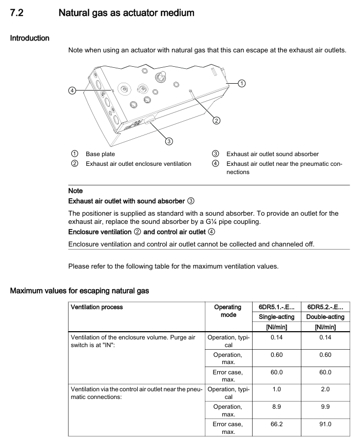
Special requirements for natural gas operation: Only intrinsically safe (Ex ia) equipment can be used; Prohibited from operating in enclosed spaces; Adequate ventilation is required (see technical data for maximum ventilation capacity); Prohibit the use of mechanical limit switch modules; Relieve pressure for at least 2 minutes before maintenance
Initialization type and process
Initialization type:
Automatic initialization: Automatically detect the direction of action, actuator stroke/rotation angle, stroke time, and adapt control parameters, with a time consumption of ≤ 15 minutes
Manual initialization: manually set stroke/rotation angle, and automatically detect other parameters (applicable to PTFE lined valves)
Data replication: Copy the initialization data of the original device when replacing it to avoid process interruption
Core parameters (1-5):
Parameter function applicable to actuators, optional parameter value units
1. YFCT action direction/detection type linear/angular stroke linear: WAY/- WAY/FWAY/- FWAY/LWAY; Angular travel: turn/- turn; NCS adaptation: ncSt/ncSL/ncSLL, etc-
2. YAGL locator shaft rated rotation angle stroke 33, 90 degrees
3. YWAY travel range (optional) Linear (WAY/- WAY/ncSLL/- ncLL) OFF, 5, 10, 15, 20 (33 ° short lever); 25, 30, 35 (90 ° short leverage); 40~130 (90 ° long lever) mm
4. InitiatA automatically initializes all NOINI (uninitialized) and Strt (start)-
5. InitiatM manually initializes all NOINI (uninitialized) and Strt (start)-
Automatic initialization steps for linear actuators:
Press and hold the button for 5 seconds to enter configuration mode → Call 2. YAGL to confirm consistency with the transmission ratio selector → Set 3. YWAY (optional) → Call 4. InitiatA and press and hold for 5 seconds to start → Display "FINSH" after completion
Automatic initialization of angular actuator: Similar to linear actuator, default 2. YAGL=90 °, and display the total rotation angle after initialization
Maintenance and upkeep
Basic security requirements
Only authorized personnel from Siemens are authorized to perform repairs; The surface area of equipment in hazardous areas with dust exceeding 5mm needs to be cleaned (to avoid overheating); When cleaning, use a damp cloth or neutral cleaner, and do not use solvents such as acetone (to avoid damaging the plastic/paint surface)
After maintenance, it is necessary to correctly connect the equipment and close the casing to ensure the explosion-proof level; Button lock only allows authorized personnel to cancel (to avoid parameter errors affecting process safety)
Filter cleaning (core maintenance item)
Cleaning methods for different shell materials:
Polycarbonate (6DR5. 0), Aluminum Shell (6DR5. 3), Explosion proof Aluminum Shell (6DR5. 5): Disconnect the air source → Remove the pipeline → Open the cover → Unscrew the 3 screws of the pneumatic terminal board → Remove the filter screen/O-ring → Clean with compressed air → Reinstall in the original order (polycarbonate shell screws are self tapping screws, need to first find the thread counterclockwise before tightening)
Stainless steel shell (6DR5. 2), explosion-proof stainless steel shell (6DR5. 6), single acting aluminum shell (6DR5. 1): Disconnect the air source → remove the pipeline → remove the metal filter → clean and reinstall
Repair and Disposal
Repair: The faulty equipment needs to be sent for repair along with the fault information, and the original equipment serial number needs to be provided when ordering replacement equipment; Prohibition of unauthorized repairs (cancellation of warranty and certification)
Return: Please provide the waybill, return documents, and proof of cleaning. If there is no proof of cleaning, a cleaning fee will be charged
Disposal: Compliant with the WEEE Directive (2012/19/EC), municipal waste disposal is prohibited and must be returned to the supplier or local compliant recycling agency
Technical data
General Parameters
Working conditions: temperature -30~+80 ° C (-40~+80 ° C with Z M40 order code), altitude ≤ 2000m, humidity 0~100%, protection level IP66 (NEMA 4X), anti vibration (2~27Hz: 3.5mm amplitude); 27~300Hz: 98.1m/s ² acceleration
Pneumatic data: Air source pressure of 1.4~7 bar (fault holding double acting 3~7 bar), air quality meets ISO 8573-1 (solid particle Class3, pressure dew point Class3, oil content Class3), valve leakage<6 × 10 ⁻⁴ Nm ³/h, controlled air consumption<3.6 × 10 ⁻² Nm ³/h
Various versions of electrical data (excerpt)
With/without HART: 2-wire system maintaining current ≥ 3.6mA; without HART version (6DR50.) typical load voltage 6.36V (318 Ω), maximum 6.48V (324 Ω); The typical load voltage for the HART version (6DR52.) is 8.4V (420 Ω), with a maximum of 8.8V (440 Ω)
PROFIBUS PA/Foundation Fieldbus: Bus voltage 9~32V (intrinsic safety type 9~24V), current consumption 11.5mA ± 10%, safe shutdown input (terminal 81/82) electrically isolated from the bus circuit
Optional module parameters (excerpt)
Alarm module (6DR4004-6A/8A): 3-channel binary output, intrinsically safe maximum input 30V/100mA/1W, signal high level>2.1mA, low level<1.2mA
Position feedback module (6DR4004-6J/8J): 4-20mA current output (2-wire system), transmission error ≤ 0.3%, temperature impact 0.1%/10K, intrinsic safety type only applicable to T4 temperature level
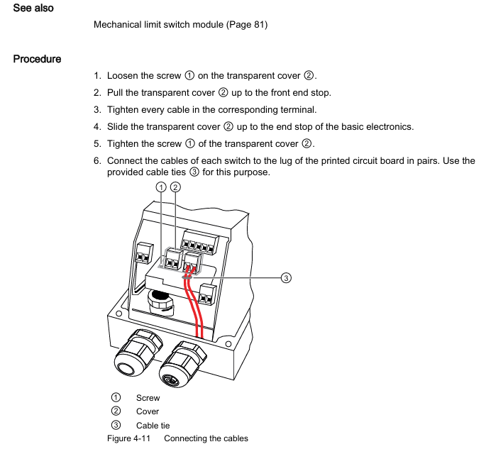
Mechanical limit switch module (6DR4004-6K/8K): 2 limit contacts, maximum switch current 4A (AC/DC), intrinsic safety maximum voltage 30V, UL certified version (6DR4004-6K) maximum voltage 30V AC/DC, 8K version without UL certification
- YOKOGAWA
- Reliance
- ADVANCED
- SEW
- ProSoft
- WATLOW
- Kongsberg
- FANUC
- VSD
- DCS
- PLC
- man-machine
- Covid-19
- Energy and Gender
- Energy Access
- Renewable Integration
- Energy Subsidies
- Energy and Water
- Net zero emission
- Energy Security
- Critical Minerals
- A-B
- petroleum
- Mine scale
- Sewage treatment
- cement
- architecture
- Industrial information
- New energy
- Automobile market
- electricity
- Construction site
- HIMA
- ABB
- Rockwell
- Schneider Modicon
- Siemens
- xYCOM
- Yaskawa
- Woodward
- BOSCH Rexroth
- MOOG
- General Electric
- American NI
- Rolls-Royce
- CTI
- Honeywell
- EMERSON
- MAN
- GE
- TRICONEX
- Control Wave
- ALSTOM
- AMAT
- STUDER
- KONGSBERG
- MOTOROLA
- DANAHER MOTION
- Bentley
- Galil
- EATON
- MOLEX
- Triconex
- DEIF
- B&W
- ZYGO
- Aerotech
- DANFOSS
- KOLLMORGEN
- Beijer
- Endress+Hauser
- schneider
- Foxboro
- KB
- REXROTH
- YAMAHA
- Johnson
- Westinghouse
- WAGO
- TOSHIBA
- TEKTRONIX
- BENDER
- BMCM
- SMC
- HITACHI
- HIRSCHMANN
- XP POWER
- Baldor
- Meggitt
- SHINKAWA
- Other Brands
- UniOP
- KUKA
- IBA
- Beckhoff
-
Basler Electric DECS-250-CN1SN1N Automatic Voltage Regulator for Generator Excitation Control
-
ADLINK CPCI-6860A - 51-31310-OB10 industrial motherboard CompactPCI SBC
-
ADLINK AmITX-SL-G-H110 - 51-7A104-0A30 Mini-ITX Industrial Motherboard
-
ADLINK PXI-2005-003 - CPCI Industrial PC Data Acquisition Card Multi-Function DAQ
-
ADLINK DININ-814M - 51-14032-0A3D SCSI-100P cable connection Interface Terminal Board
-
ADLINK CPCI-3920NA/C2D15/M1G - 3U CompactPCI Intel Core 2 Duo Single Board Computer
-
ADLINK PCIE-8560 - 51-18014-0A20 Communication Card High Speed DAQ
-
ADLINK PCI-C154+ - Motion Control Card 4-axis Motion Controller Board
-
ADLINK PCI-RTV24 - image capture card Analog Video Frame Grabber
-
ADLINK NuPRO-842LV/P - 51-41360-0B30 Industrial Motherboard CPU Board
-
ADLINK cBP-3208/3208R - CPCI Board 3U 8-Slot CompactPCI Backplane
-
ADLINK PCI-8164 - 4-Axis Motion Controller PCI Card 51-12406-0A40
-
ADLINK PCIe-GIE64+ - 4-CH GigE Vision PoE+ Frame Grabber Video Capture Card
-
ADLINK CPCI-6860 / 6860A - CompactPCI Dual Xeon Single Board Computer
-
ADLINK IEC-915GV - REV 1.1 Industrial motherboard CPU Board
-
ADLINK ND-6520 - Technology RS-232 to RS-422RS-485 Converter NuDAM Module
-
ADLINK RTV-24 / PCI-MP4S - 51-12519-1C30 4-Channel Real Time Video Capture Board
-
ADLINK cPCI-6910 / cPCI-6910AM/M1G - cPCI-6910AM/DXL16/M1G/S80G(G)-3120 BOARD CompactPCI SBC
-
ADLINK NUPRO-A40H - Linghua 51-41807-1A30 Industrial Control Computer Motherboard
-
ADLINK USB-3488A - USB to GPIB INTERFACE USB-3488A(G) Controller Module
-
ADLINK PCI-8134A - motion control card 4-Axis Controller Card
-
ADLINK PCI-7432 - Board 32-Channel input / 32-output Isolated Digital I/O PCI Card
-
ADLINK PCI-8134A - 51-12421-0A10 motion controller card tested
-
ADLINK LPCIe-7230 - 32 CH Isolated Input/output Card 2 Interrupts Low Profile PCIe
-
ADLINK NuPRO-E340 - industrial computer motherboard 51-47807-0A30 PICMG 1.3 SHB
-
ADLINK PCI-7434 - High-speed Digital Acquisition Card 64-CH Isolated DO Card
-
ADLINK NuPRO-E330 - 51-41805-0A20 Indsutrial Board SHB Single Board Computer
-
ADLINK PCI-7248 - OPTO-22 48 CHANNEL DIO DIGITAL TTL/DTL I/O 51-12006-0A40 GP
-
ADLINK PCI-8134 - Motion control card 4-Axis Controller Card
-
ADLINK AMP-208C - Movimiento Control Tarjeta 51-12420-1A20 W/Expansión & Breakout
-
ADLINK PCI-8164 - 51-12406-0A40 PCB Board 4-Axis Motion Controller Card
-
ADLINK DIN-68Y-SGII / DIN-68M-J3A - Terminal Board Connector Interface Block
-
ADLINK PCIe-7432 - Technology 51-18402-0A10 PCIe Card With High Input Range
-
ADLINK PCI-8144 / PCI-8144N - Motion control card 4-Axis Stepper Controller Card
-
ADLINK HSL-HUB3/REPEATER - HIGH SPEED LINK EXTENSION MODULES Distributed Hub Module
-
ADLINK ND-6017 - Data Logging + Acquisition 8CH A/D input Mod NuDAM Module
-
ADLINK LPCIe-7250 - data acquisition card Low Profile 8-CH Relay Output Card
-
ADLINK PCI-7432 - I/O card 64-CH Isolated Digital Input Output PCI Card
-
ADLINK IMB-M43H - industrial control computer motherboard Q87 Chip Micro-ATX
-
ADLINK MP-C154 - Motion control Card 4-Axis Motion Controller Board
-
ADLINK PCI-RTV24 - image capture card Video Frame Grabber Card
-
ADLINK PCI-7250 - 8-CH Relay Output & 8-CH Isolated DI Card
-
ADLINK PCI-6308V - 8-CH 12-Bit Isolated Analog Output PCI Card PCB-I-E-1148=6EX2
-
ADLINK PCI-7248 - capture card 48-CH Opto-22 Compatible DIO Card
-
ADLINK HSL-AI16A02-M-VV - Analog Input Output Distributed Module
-
ADLINK NuPRO-A301 - Rev:1.4 NUPRO-A301 PICMG Full-Size Single Board Computer
-
ADLINK PCI-6208V-GL - 8-CH Voltage Analog Output PCI Card
-
ADLINK PCI-8134A - 51-12421-0A10 4-Axis Motion Controller Card
-
ADLINK MNET-S23 - TECHNOLOGY MNET S23 - SERVO DRIVER CONTROL MODULE
-
ADLINK M-342 - ATX I3 I5 I7 Q67 Industrial Motherboard
-
ADLINK NUPRO-780 - Industrial Motherboard CPU Board PICMG SBC
-
ADLINK MP-C154 / MP-C152 - 4-Axis Motion Control Card Pulse-Train Controller
-
ADLINK NuPRO-935A/LV10B0 - Motherboard 51-41802-0A10 GP w/RAM Industrial Control Board
-
ADLINK MP-C154 - Motion control card 4-Axis Motion Controller Mainboard
-
ADLINK PCI-7250 - PCI Acquisition Card 8-CH Relay Output Isolated DI Card
-
ADLINK ACL-7124 - Technology Inc.24 DIO Card Digital Input Output Card
-
ADLINK PCI-8554 A2 - Timer/Counter Data Acquisition Card
-
ADLINK DIN-825-GP4 - Terminal Block Interface Board Breakout Module
-
ADLINK NuPR0-761 - REV:1.1 Industrial motherboard Full-Size PICMG SBC
-
ADLINK MXE-1401/M8G (G) - Matrix Fanless Embedded Computer Industrial PC
-
ADLINK HSL-DI16DO16-UD-NN - Digital 16 Channel I/O Mod Distributed I/O Module
-
ADLINK ND6520 - NUDAM INTELLIGENT DA&C MODULE RS232-RS-422/RS485 CONVERTOR
-
ADLINK NUPRO-761 - REV:1.1 Industrial Motherboard CPU Board
-
ADLINK AMP-208C - Motion Control Card 51-12420-1A20 DSP-based 8-axis
-
ADLINK NuPRO-A301REV 1.4 - with packaging industrial computer motherboard PICMG SBC
-
ADLINK PCM-9112+ - 51-12300-0A2 industrial motherboard Multi-Function DAQ PC/104 Module
-
ADLINK PCM-7250+ - 8-CH Relay Outputs & 8-CH Isolated DI Module PC/104
-
ADLINK PCI-RTV24 - Image capture card Analog Video Frame Grabber
-
ADLINK PCI-8134 - Motion Controller PCI Card 4-Axis Controller Board
-
ADLINK PCI-7432 - Isolated Digital I/O PCI Card
-
ADLINK PCI-8554 A2 - acquisition card Timer/Counter Card
-
ADLINK PCI-8132 - Rev.A2 2-Axis Servo & Stepper Motion Controller Card
-
ADLINK PCI-8132 - Data Acquisition card 2-Axis Motion Controller Card
-
ADLINK EBP-13E4 - 51-46703-0A30 Industrial Backplane Board Passive Backplane
-
ADLINK PCI-800L - Electronic Card Interface Controller Card
-
ADLINK PCIe-GIE72 - 51-18531-0A10 PCB Board GigE Vision Frame Grabber
-
ADLINK DAQ-2010(G)-OOBO - Simultaneous-Sampling Multi-Function DAQ Card
-
ADLINK PCI-9112 - REV.B1 Multifunction DAQ Card Data Acquisition Card
-
ADLINK PCI-7230 - 51-12003-DA60 32-CH Isolated Digital I/O Card
-
ADLINK PCI-7432 - Data Acquisition Card Isolated Digital I/O PCI Card
-
ADLINK ETX-AT-N270-18/LXE - 51-71111-0A20 ETX CPU Module Motherboard
-
ADLINK HSL-DI32-UD-N - DIGITAL INPUT 32 POINTS MODULE Distributed I/O
-
ADLINK AMP-204C - Motion Control card DSP-Based 4-Axis Advanced Controller
-
ADLINK MNET-4XMOG-0050 - Four-axis Motion Controller Distributed Motion Module
-
ADLINK AMP-204C - Motion control card DSP-Based 4-Axis Pulse-Train Controller
-
ADLINK PCI-7442 - Switch card 64-Channel Datalogging & Acquisition Card
-
ADLINK M-302 - Industrial control motherboard ATX PC Board
-
ADLINK NUPRO-852 / NUPRO-852LV - Industrial motherboard Single Board Computer
-
ADLINK PCI-8134 - REV.B1. 4-Axis Motion Controller Card
-
ADLINK PCI-GIE62 + - 51-18502-0A20 2-CH GigE Vision Frame Grabber PoE Card
-
ADLINK PCI-MPG24 - 51-12523-0B20 MPEG4 Card Video Compression Hardware
-
ADLINK HSL-TB32-M-DIN - 32-CH I/O TERMINAL W/ HSL-AI16AO2-M-VV MODULE
-
ADLINK PCI-M114-GL - PCB Ver 2.1 Motion Controller Axis Card
-
ADLINK IMB-M40H - SYM76996H61 motherboard Industrial Computer Mainboard
-
ADLINK NUPRO-A40H - 51-41807-1A20 industrial control motherboard H61 Chip
-
ADLINK PCI-M114-GL - Axis Card Data Acquisition Card PCB VER2.2 Motion Controller
-
ADLINK PCI-8134 - Motion Controller PCI Card 4-Axis Controller Board
-
ADLINK PCI-8102 - Motion control card 2-Axis Servo & Stepper Controller
-
ADLINK NuPRO-841REV:3.0 - motherboard Industrial Control PC Board
-
ADLINK HSL-TB32-U-DIN REV A1 - Breakout Terminal Board Field I/O Module
-
ADLINK AMP-204C - Motion Control card DSP-Based 4-Axis Pulse-Train Controller
-
ADLINK NUPRO-A40H - 51-41807-1A20 industrial control motherboard H61 PC Board
-
ADLINK PCI-6308A / PCI-6308V - 51-12202-0A50 Isolated Analog Output Card
-
ADLINK AMP-204C - DSP-Based 4-Axis Advanced Pulse-Train Motion Controller
-
ADLINK PCI-7434 - Technology 64-Channel Isolated Digital I/O PCI Cards
-
ADLINK CPCI-6840 / CPCI-6840V / PM16/M1G-12G0 - CompactPCI Single Board Computer CPU Module
-
ADLINK PCIE-GIE74 - Motherboard Video Capture Card 51-18531-0A10 Frame Grabber
-
ADLINK NuPRO-E330 - industrial computer equipment motherboard Control Mainboard
-
ADLINK AMP-208C / 51-12420-1A20 - Motion Control Card W/ Expansion & Breakout Board
-
ADLINK HPCI-14S12U - industrial computer baseboard Passive Backplane 14 Slots
-
ADLINK PCI-8164 - 4-Axis Motion Controller PCI Card W/ 1x Cable, 1x Breakout Box
-
ADLINK PCIe-RTV24 - 51-18016-0A20 Image Acquisition Video Capture Card
-
ADLINK M-342 - 5 PCI ATX Motherboard Industrial PC Mainboard
-
ADLINK PCI-FIW64 - 4/2 Channel IEEE1394B Image Capture Card FireWire Frame Grabber
-
ADLINK PCI-7432 - digital IO card 64-CH Isolated Digital Input Output Card
-
ADLINK 51-12001-0C20 - Circuit Board PCI-7200 Data Acquisition Controller Card
-
ADLINK PXI-3920 - PXI 3U cPCI Industrial Controller Embedded System CPU Board
-
ADLINK NuPRO-841REV:2.0 - motherboard Industrial Control PC Board
-
ADLINK NuPro-E330 - 51-41805-0A20 PCB Industrial Control Computer Motherboard
-
ADLINK PCI-RTV24 - Image capture card Analog Video Frame Grabber
-
ADLINK PCI-7442 - Switch card 64-Channel Datalogging & Acquisition Card
-
ADLINK HPX-13S4 - device baseboard Passive Backplane Riser Card
-
ADLINK PCI-9112 REV A.1 - Multi Function DA&C Board Data Acquisition Card
-
ADLINK PCI-7248 - 51-12006-0A40 Card Control 48-CH Digital I/O Module
-
ADLINK CPCI-6860 / 6860A - motherboard CompactPCI Dual Xeon Single Board Computer
-
ADLINK DPAC-3020-11(G) - Embedded PC Automation Controller Machine Control Board
-
ADLINK NuPRO-841 REV:1.0 - industrial control motherboard CPU Board
-
ADLINK MNET-4XMOG-0050 - Four-axis Motion Controller MNET Motion Control Card

K-JIANG

Add: Jimei North Road, Jimei District, Xiamen, Fujian, China
Tell:+86-15305925923