
K-WANG


ABB SPAU 341 C Voltage Regulator
Core value: Supports independent voltage regulation of a single transformer and parallel operation of multiple transformers, with functions such as line voltage drop compensation, overcurrent/undervoltage lockout, overvoltage detection, etc., to meet the stability requirements of industrial power supply;
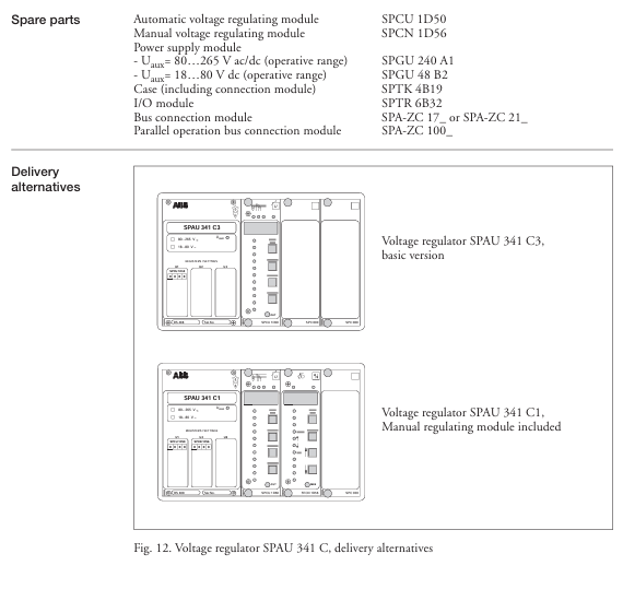
Module composition: It consists of an automatic voltage regulation module (SPCU 1D50), a manual voltage regulation module (SPCN 1D56), a power module (SPGU 240 A1/SPGU 48 B2), an I/O module (SPTR 6B32), and a motherboard. It supports fiber optic serial bus communication (requires SPA-ZC series bus modules).
ABB SPAU 341 C Voltage Regulator
Product basic positioning and core functions
1. Product positioning
Application scenario: Designed specifically for on load tap changers in distribution substations, the secondary voltage of the transformer is regulated by controlling tap changers to ensure stable load voltage and adapt to 50/60Hz power grids;
Core value: Supports independent voltage regulation of a single transformer and parallel operation of multiple transformers, with functions such as line voltage drop compensation, overcurrent/undervoltage lockout, overvoltage detection, etc., to meet the stability requirements of industrial power supply;
Module composition: It consists of an automatic voltage regulation module (SPCU 1D50), a manual voltage regulation module (SPCN 1D56), a power module (SPGU 240 A1/SPGU 48 B2), an I/O module (SPTR 6B32), and a motherboard. It supports fiber optic serial bus communication (requires SPA-ZC series bus modules).
2. Core Function List
Functional categories, specific abilities, and application value
Voltage control with automatic/manual dual-mode voltage regulation, adjusting the voltage to adapt to load changes through the "Raise/Lower" signal of the tap changer, and maintaining stable secondary voltage
Compensation function circuit voltage drop compensation (U ₐ), compensating for voltage loss caused by circuit resistance (R) and reactance (X) to ensure that the voltage at the remote load end meets the standard, avoiding high near end voltage/low far end voltage
Protection lockout overcurrent lockout (I>), undervoltage lockout (U<), overvoltage detection (U>), external lockout input prevents the tap changer from operating in fault states (such as short circuit, abnormal voltage), extending equipment life
Parallel operation supports three parallel control principles: Master/Slave, Negative Reaction, and Minimizing Circulating Current. When multiple transformers supply power to the same bus, they balance the load and circulating current to avoid equipment overload
Real time self inspection of self-monitoring hardware/software, triggering IRF (Internal Relay Fault) alarm in case of failure, blocking output to improve system reliability, and reducing the risk of fault expansion
Data exchange with digital display of set/measured values, RS485 serial interface, fiber optic bus communication for convenient on-site debugging and remote monitoring, compatible with substation automation systems
Core working principle and key parameters
1. Voltage regulation core logic
Control voltage calculation: The controller calculates the target control voltage (U ₚ) through "reference voltage (U ₛ) ± line voltage drop compensation (U_z) ± circulating current compensation (U_ci) - set voltage drop (U_rsv)", and the formula is:
Uₚ = Uₛ ± U_z ± U_ci - U_rsv
Adjustment trigger mechanism:
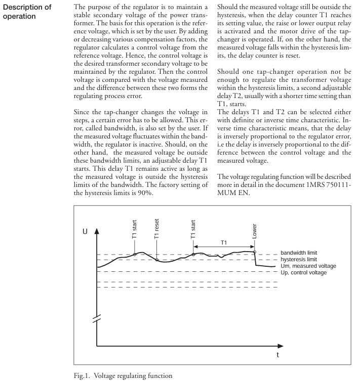
Compare the measured voltage (U ₘ) with the control voltage (U ₚ). If U ₘ exceeds the "bandwidth (∆ U ₛ)" range (default ± 1.5% U ₙ), initiate the first delay (T1, default 60s);
If U ₘ still exceeds the hysteresis range (∆ U ₕ, default 90% ∆ U ₛ) during the delay period, the tap changer will be triggered;
If a single action does not cause U ₘ to return to bandwidth, initiate the second delay (T2, default 30s) and repeat the adjustment until the voltage meets the standard;
The delay feature supports both "definite time limit" and "inverse time limit" (the delay is inversely proportional to the voltage deviation, and the larger the deviation, the shorter the delay).
2. Key technical parameters (core indicators)
Specific specifications for parameter categories
Voltage input rated voltage U ₙ: 100V/110V/120V (line voltage), continuous withstand voltage 2U ₙ, power consumption<0.5VA, suitable for different regional power grid rated voltages
Current input rated current I ₙ: 1A/5A (optional), 1A model can withstand 4A and 25A continuously for 10 seconds; 5A model can withstand 20A and 100A continuously for 10 seconds, compatible with current transformers (CT) of different transformation ratios
Output contact adjustment contact (Raise/Power): 250V AC/DC, continuous 5A, 0.5s on-off 30A; signal contact (lockout/alarm): 250V AC/DC, continuous 5A, compatible with tap changer drive circuit and alarm circuit
Power module SPGU 240 A1: 80~265V AC/DC (compatible with 110/230V mainstream voltage); SPGU 48 B2: 18~80V DC (compatible with low-voltage DC system) to meet different substation power configurations
Environmental adaptability: working temperature -10~+55 ℃, storage temperature -40~+70 ℃, humidity 5%~95%, non condensing, protection level IP54 (embedded installation), suitable for industrial harsh environment, dustproof and splash proof
Communication capability: Fiber optic serial bus, ASCII encoding, speed 4800/9600 Bd, supports SPA-ZC series modules (SPA-ZC 17/21 for plastic fiber optic and SPA-ZC 17 MM/21 MM for glass fiber optic) to achieve data exchange among multiple regulators, supports parallel operation and remote monitoring
Core configuration and operation process
1. Key configurations before installation (mandatory steps)
(1) Hardware wiring specifications
Core input/output wiring:
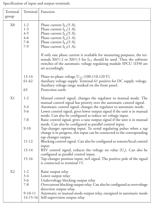
Voltage input: X0/13-14 terminals are connected to the secondary side line voltage of the transformer (U ₁₂, 100/110/120V);
Current input: Connect the X0 terminal to three-phase current (1A to 1-3/4-6/7-9, 5A to 1-2/4-5/7-8), and a single transformer can only measure the L1 phase current (selected through SGF2/6/7 software switch);
Control output: X2 terminal outputs Raise/Power signal to the tap changer, X1 terminal connects external control signal (automatic/manual switching, external locking);
Grounding requirement: Connect the protective ground through the X0/63 terminal to ensure reliable grounding between the module and chassis, avoiding electromagnetic interference.
(2) Core parameter setting (configured through panel buttons or serial port)
Parameter Name Setting Range Default Values Key Role
Reference voltage U ₛ 0.85~1.15U ₙ 1.00U ₙ Set target secondary voltage
Bandwidth ∆ U ₛ 0.60~9.00% U ₙ 1.50% U ₙ Voltage fluctuation tolerance range, avoiding frequent adjustments
Delay T1/T2 0.0~300s 60s/30s to prevent momentary voltage fluctuations from triggering misoperations
Overcurrent lockout I>1.00~2.00I ₙ 2.00I ₙ When overcurrent occurs, voltage regulation is prohibited to protect the tap changer
Line compensation U ᵣ/U ₓ 0.0~25.0% U ₙ 0.0% U ₙ Compensation line impedance voltage drop, U ᵣ=√ 3I ₗₒₐ𝒹 R × 100/U ₙ, U ₓ=√ 3I ₗₒₐ𝒹 X × 100/U ₙ
2. Operation mode and process
(1) Automatic voltage regulation mode (default, SPCU 1D50 dominant)
Trigger condition: If U ₘ exceeds the range of ∆ U ₛ and lasts for T1 time, the controller outputs Raise/Power signal to drive the tap changer;
Compensation logic: Based on the load current (I ₗₒₐ𝒹) and the line parameters (R/X), U_z is automatically calculated to increase the remote voltage (such as a line voltage drop of 2V, U_ is automatically increased by 2V).
(2) Manual voltage regulation mode (dominated by SPCN 1D56)
Activation method: Switch through the panel "MAN" button or external "MAN '" input, and the MAN indicator light will turn on;
Operation steps: Press the "Raise"/"Lower" button, the corresponding indicator light flashes → Confirm that there is no lock (I>/U<light is not on) → Press the corresponding button again to trigger the tap changer action, and the TCO light is on to indicate that the tap changer is running.
(3) Multiple transformers running in parallel (three modes)
Parallel mode is suitable for key configurations in applicable scenarios
Master/Slave mode: The main regulator of a transformer with the same capacity and tap voltage measures voltage/current and controls it. The slave regulator follows the action of the main regulator and needs to be directly wired to connect the master slave "up/down" output and input
Negative Reaction mode: Transformers with different capacities and tap voltages do not require physical connections. The "load phase shift" parameter is set, and the controller compensates for the voltage deviation between the measured phase shift and the set value, adapting to the parallel connection of dispersed substations
In scenarios where there are large differences in transformation ratio/capacity and large fluctuations in reactive load, the Minimum Circulating Current mode needs to be paired with the SPA-ZC 100 bus module. Multiple regulators exchange current/phase shift data, calculate and minimize circulating current, and support up to 3 parallel regulators
Fault handling and maintenance
1. Interpretation of status indicator lights (core fault diagnosis basis)
Suggestions for handling the meaning of indicator light status
Module status (MS): red, constantly on, unrecoverable fault (such as hardware damage). Power off and restart, if ineffective, check the connection between the I/O module and the motherboard, and contact after-sales service
Overcurrent lockout (I>), red constant light. If the current exceeds the set value, check if the load is overloaded and if the CT wiring is normal. After troubleshooting, reset
Under voltage lockout (U<), red constant light, voltage lower than U<set value (default 0.7U ₙ), check the grid voltage. If the grid is normal, adjust U<set value
Overvoltage detection (U>): The red constant light indicates that the voltage is higher than the set value (default is 1.25U ₙ), triggering "rapid voltage reduction" without manual intervention. After the voltage is restored, it will automatically exit
Self check fault (IRF): The hardware/software fault record of the red module is constantly on, and the display screen shows the fault code (such as 1-030=program memory fault). Contact after-sales maintenance for assistance
2. Common fault codes and their solutions
Fault code, fault type, handling measures
1-004 voltage regulation control circuit fault check tap changer "up/down" coil wiring, confirm power module output voltage
1-030 Program Memory (ROM) malfunction module internal failure, SPCU 1D50 module needs to be replaced
1-050 working memory (RAM) failure, power off and restart. If the failure persists, replace the motherboard
1-051 Parameter Memory (EEPROM) Failure: Format EEPROM with V167 parameters and reconfigure parameters
3. Key points of daily maintenance
Regular inspection: Check the terminal wiring for looseness and proper heat dissipation every month, and clean the module dust screen (if any) every quarter;
Parameter backup: Backup parameters (such as U ₛ, ∆ U ₛ, U ᵣ/U ₓ) through serial software to avoid module failure causing parameter loss;
Spare parts preparation: It is recommended to reserve key spare parts such as power module (SPGU 240 A1) and I/O module (SPTR 6B32) to shorten the time for fault repair.
Installation and selection suggestions
1. Installation requirements
Environmental conditions: Avoid high temperature heat sources (such as the transformer body), installation location temperature ≤ 55 ℃, humidity ≤ 95% non condensing, protection level IP54 (requires compatible casing);
Wiring specifications: Voltage/current signal lines and power lines should be laid separately. The length of the fiber optic bus cable should be ≤ 100m (plastic fiber)/2km (glass fiber), and the bending radius should be ≥ 10 times the cable diameter;
Size and fixation: Adopting embedded installation, the panel opening size needs to match (214 × 139mm ± 1mm), and the installation depth can be adjusted through the SPA-ZX series height increasing frame (3 specifications).
2. Selection and matching
Power module selection: Select SPGU 240 A1 (80~265V AC/DC) for conventional scenarios, and SPGU 48 B2 (18~80V DC) for low-voltage DC systems;
Bus module selection: SPA-ZC 17 BB/21 BB for plastic fiber optic, SPA-ZC 17 MM/21 MM for glass fiber optic, and SPA-ZC 100 BB/MM for parallel minimum circulating current;
Cable selection: 100V shielded wire is used for voltage signals, CT dedicated shielded wire is used for current signals, and ABB recommends plastic/glass fiber optic cables (such as SPA-ZP 25A05) for optical fibers.
- YOKOGAWA
- Reliance
- ADVANCED
- SEW
- ProSoft
- WATLOW
- Kongsberg
- FANUC
- VSD
- DCS
- PLC
- man-machine
- Covid-19
- Energy and Gender
- Energy Access
- Renewable Integration
- Energy Subsidies
- Energy and Water
- Net zero emission
- Energy Security
- Critical Minerals
- A-B
- petroleum
- Mine scale
- Sewage treatment
- cement
- architecture
- Industrial information
- New energy
- Automobile market
- electricity
- Construction site
- HIMA
- ABB
- Rockwell
- Schneider Modicon
- Siemens
- xYCOM
- Yaskawa
- Woodward
- BOSCH Rexroth
- MOOG
- General Electric
- American NI
- Rolls-Royce
- CTI
- Honeywell
- EMERSON
- MAN
- GE
- TRICONEX
- Control Wave
- ALSTOM
- AMAT
- STUDER
- KONGSBERG
- MOTOROLA
- DANAHER MOTION
- Bentley
- Galil
- EATON
- MOLEX
- Triconex
- DEIF
- B&W
- ZYGO
- Aerotech
- DANFOSS
- KOLLMORGEN
- Beijer
- Endress+Hauser
- schneider
- Foxboro
- KB
- REXROTH
- YAMAHA
- Johnson
- Westinghouse
- WAGO
- TOSHIBA
- TEKTRONIX
- BENDER
- BMCM
- SMC
- HITACHI
- HIRSCHMANN
- XP POWER
- Baldor
- Meggitt
- SHINKAWA
- Other Brands
- UniOP
- KUKA
- IBA
- Beckhoff
- ADLINK
-
ADLINK HPCI-14S12U - Industrial Control Backplane 12PCI Backplane PCI-14S Passive Backplane
-
ADLINK PCIe-GIE74C - image acquisition card 4-CH GigE Vision PoE+ Frame Grabber
-
ADLINK PCI-8164 - control card 4-Axis Advanced Motion Controller Board
-
ADLINK PCIe-U304 - 4 Port USB3 PCIe Frame Grabbers USB Screw Hole Card
-
ADLINK PCI-9112 - Multi-Function Data Acquisition Card DAQ Card
-
ADLINK PCI-7432 - 51-12013-0A50 4-CH Isolated Numérique I/O PCI Cartes Digital I/O Card
-
ADLINK PCA-6106P3-0C1 REV.C1 - backplane 6-Slot Passive Backplane Board
-
ADLINK PCI-7224 - 24-CH Opto-Isolated Digital I/O PCI Board
-
ADLINK CPCI-7433R(G) - Digital Input Board Rear I/O CompactPCI Card
-
ADLINK EBP-13E4 - 51-46703-0A30 Industrial PC Backplane Passive Backplane
-
ADLINK PCIE-HDV62 - Image acquisition card High Definition Video Frame Grabber
-
ADLINK EBP-13E4 - 51-46703-0A30 Industrial Backplane Board Passive Backplane
-
ADLINK 90111-B1 / CPCI-6770 - PCB CPU MODULE CompactPCI Single Board Computer
-
ADLINK PCI-7248 - DATA ACQUISITION PCI CARD 48-CH Parallel Digital I/O Board
-
ADLINK PCI-7230 - 51-12003-0a50 board PCI7230 32-CH Isolated Digital I/O Card
-
ADLINK PCI2A000CB - 51-20000-0B30 Multi-Function DAQ Card Baseboard
-
ADLINK PCI-8134-005 - 4-Axis Motion Controller Card
-
ADLINK PCI-7224 - 24-CH Opto-Isolated Digital I/O PCI Card
-
ADLINK PCI-7434 - 64-CH Isolated Digital Output Card
-
ADLINK PCI-8132 - motion control card 2-Axis Servo & Stepper Controller
-
ADLINK PCI-8134 - Motion Controller PCI Card 4-Axis Controller Board
-
ADLINK PCI-8164 - Motion Control Card 51-12406-0A40 4-Axis Controller
-
ADLINK 51-12001-0C20 - Circuit Board Data Acquisition Interface Module Hardware
-
ADLINK NuPR0-840 - industrial control motherboard Full-Size PICMG CPU Board
-
ADLINK PCI-7444 - 51-12023-0A10 card 128-CH Isolated Digital Output Board
-
ADLINK PCI-1612B - data acquisition card 4-Port RS-232/422/485 Serial Communication Card
-
ADLINK PCI-6208V 009 - 8/16-CH 16-Bit Analog Output Cards PCB-I-E-482=6BX3
-
ADLINK NUPRO-935A/LV - industrial control motherboard Full-Size PICMG SBC Board
-
ADLINK PCI-9114DG - Multi-Function DAQ Card Data Acquisition PCI Card
-
ADLINK ACL-7130 - Data acquisition card Isolated Digital I/O Board
-
ADLINK ABX-6300D-4E1-BP - board ABX6300D4E1BP Video Interface Expansion Card
-
ADLINK CPCI-6940 - CPCI-6940/D1539/M16-0(EA)-000E 6U CompactPCI Processor Board
-
ADLINK NuPRO-760 - industrial control motherboard Half-Size PICMG SBC CPU Board
-
ADLINK IMB-M42H (G)-0020 - industrial control motherboard LGA1155 Micro-ATX Mainboard
-
ADLINK RTV-24 / PCI-MP4S - 51-12519-1C30 4-Channel Real Time Video Capture Board
-
ADLINK PCI-8134 - 4-Axis Servo & Stepper Motion Controller Card
-
ADLINK MXC-6101D - V.PC000.002.ST.00 Box PC Configurable Embedded Computer
-
ADLINK PCI-8134A - 51-12421-0A10 Motion Control Card 4-Axis Controller Card
-
ADLINK DIN-100S / DIN-100SA1 - Technology SCSI-II TB 100-PIN Terminal Block Board
-
ADLINK DIN-812M001 / DIN812M001 - 51-14034-0A1 51140340A1 Terminal Module Breakout Interface
-
ADLINK PCI-8164 - Servo motion control 4-Axis Advanced Controller Card
-
ADLINK PCIe-GIE64 - Acquisition card GigE Vision PoE+ Frame Grabber
-
ADLINK M-302 - Industrial control motherboard ATX PC Board Mainboard
-
ADLINK PCI-8134 - Motion Controller PCI Card 4-Axis Controller Board
-
ADLINK PCI-RTV24 - Image capture card Analog Video Frame Grabber
-
ADLINK PCI-8102 - Motion control card 2-Axis Servo & Stepper Controller Board
-
ADLINK PCI-9112 REV.B1 - Card Multi-Function Data Acquisition Card
-
ADLINK HSI-DI32-M-N / HSL-TB32-M-DIN - Discrete I/O MODULE Distributed Automation Module System
-
ADLINK PCI-7296 - IO card REV.A3 96-CH Parallel Digital I/O Card
-
ADLINK DIN-814P-A4 / 814Y - terminal board Motion Control Interface Block
-
ADLINK DIN-814P-A4 - 51-14056-0A10 PCB-I-E-2736=ZA01 Screw Terminal Board Breakout
-
ADLINK M-322 - motherboard Industrial Control Computer Mainboard
-
ADLINK NUPRO-406 REV:B1 - industrial control motherboard Full-Size PICMG CPU Board
-
ADLINK AMP-204C - card DSP-Based 4-Axis Advanced Pulse-Train Controller
-
ADLINK HPCI14S REV.B1 - industrial computer baseboard 14-Slot Passive Backplane
-
ADLINK PCI-7250 - 8-CH Relay Output & 8-CH Isolated DI PCI Card
-
ADLINK EBP-13E2 - baseplate Passive Backplane Industrial Computer Chassis Board
-
ADLINK LPCI-3488A - PCI-GPIB card 51-12801-0A30 acquisition card IEEE-488 Interface Board
-
ADLINK PCI-6216V-GL - 51-12201-0C30 16-CH 16-Bit Voltage Analog Output Card
-
ADLINK ACL-8454 - 16-CH Isolated Digital I/O & 4-CH Counter Card
-
ADLINK HPCI-9S7U - backplane Passive Backplane Compatible with NuPRO-A301 852 841 842
-
ADLINK DAQ-2010-007 - Simultaneous-Sampling Multi-Function Data Acquisition Card
-
ADLINK MP-C154 - 51-64205-0A10 Motion Control Card 4-Axis Controller Board
-
ADLINK MXE-202/mSSD16B/WiFi-BT - Matrix Rugged I/O Platform Embedded Fanless Computer
-
ADLINK CM-920-R-17 - PC/104-Plus Single Board Computer Module Intel Celeron M
-
ADLINK PCI-7250 NSMP - 8-CH Relay Output & 8-CH Isolated DI Card
-
ADLINK PCI-8164 - 4-Axis Motion Controller PCI Card W/ Cable and Breakout Box
-
ADLINK EMX-100 - Ethernet-based 4-axis Motion Controllers Distributed Motion Module
-
ADLINK PCI-8134A - Press control card 4-Axis Motion Controller Board
-
ADLINK M-845EG REV:3.2 - industrial motherboard Pentium 4 Socket 478 Micro-ATX
-
ADLINK PCI-9114A Rev A2 DG - card High-Resolution Multi-Function Data Acquisition Board
-
ADLINK IEC-915GV - REV 1.1 Industrial motherboard Socket 478 CPU Board
-
ADLINK PCI-9111DG(G) - Data Acquisition Card Multi-Function DAQ Card
-
ADLINK HPCI-15S10 REV:B2 - Industrial computer base plate Passive Backplane Board
-
ADLINK NuPR0-840 / NuPR0-840DV - industrial control motherboard Full-size PICMG CPU Board
-
ADLINK RTV-24 / PCI-MP4S - 51-12519-1C30 4-Channel Real Time Video Capture Board
-
ADLINK NUPRO-780 - industrial control motherboard Pentium III Single Board Computer
-
ADLINK PCI-7296 - 0050 card 96-CH Opto-Isolated Parallel DIO Card Set
-
ADLINK NUPRO-780 - industrial control motherboard PICMG Full-Size SBC
-
ADLINK PCI-7248 - 51-12006-0A3 002 Pci 7248 48-CH Parallel Digital I/O Card
-
ADLINK cPCI-6626 - 6U CompactPCI 2.0 Blades i7-2710QE PCB-I-E-2570=9N41
-
ADLINK MXC-6322D(G) - Industrial Fanless Computer
-
ADLINK cPCI-8168-004 - CompactPci NulPC Motion Control Board 51-36402-0A3
-
ADLINK CPCI-7300[G] - COMPACTPCI Digital I/O Card Data Acquisition
-
ADLINK CPCI-6626/2710/M4G - COMPACTPCI COMPUTER BOARD
-
ADLINK cPCI-8168-009 - cPCI NulPC Motion Control Board
-
ADLINK cPCI-6626/2710/M4G - VME CPU Board Computer Board
-
ADLINK CPCI-R6200(G)-0040 - COMPACTPCI CONTROL BOARD
-
ADLINK CPCI-3840/PM18/M1G(G)-3650 - COMPACTPCI CPU Module Single Board Computer
-
ADLINK cPCI-7248 - 48-CH Opto-22 Compatible Digital I/O Module
-
ADLINK DLAP-211-JNX - NVIDIA Jetson Xavier NX Edge AI Inference Platform
-
ADLINK cPCI-3544 - Series 4-Port RS-422/485 Isolated Serial Communications Card
-
ADLINK CM1-86DX3 - PC/104 SBC Stanley Vortex86DX3 CPU 2GB Ram
-
ADLINK DLAP-211-JNX - NVIDIA Jetson Xavier NX Edge AI Inference Platform
-
ADLINK cPCI-3544 - Series 4-Port RS-422/485 Isolated Serial Communications Card
-
ADLINK CM1-86DX3 - PC/104 SBC Stanley Vortex86DX3 CPU 2GB Ram
-
ADLINK PCI-7433 - switch value acquisition card Isolated Digital Input Card
-
ADLINK PCI-9112 - 51-12252-0D20 Multi-Function Data Acquisition Card
-
ADLINK NUPRO-A301 REV:1.4 - industrial control motherboard PICMG Full-Size SBC
-
ADLINK 51-18502-0A10 - Frame Grabber Image Acquisition Interface Card
-
ADLINK PCI-7296 - 51-12009-0A50 PCB-I-E-925=6DX1 96-CH Parallel Digital I/O Board
-
ADLINK PCI-8132 GP A2 - Motion Control Card 2-Axis Servo & Stepper Controller
-
ADLINK PCI-7442 - switch quantity card data acquisition card 64-CH Isolated Card
-
ADLINK HPX-13S4 - baseboard PICMG 1.3 Passive Backplane Chassis Baseplate
-
ADLINK NuPRO-590 / NTC-567-ZM-F36 - Single Board Computer PCB-I-E-1853=9L21 Half-Size SBC
-
ADLINK PCIe-8332 - 16-axis plate Motion Control Hardware Card
-
ADLINK NuPRO-775 REV.B1 - motherboard Pentium 4 Full-Size PICMG SBC
-
ADLINK PXI-3920 - Embedded Controller 3U PXI cPCI System Intelligence Board
-
ADLINK PCI-8134 - driver card motion control card 4-Axis Controller Board
-
ADLINK HSL-DI32-M-N-011 / HSL-TB32-M-DIN - Digital Input & Base Module PLC Distributed I/O System
-
ADLINK PCI-6216V-206 / PCI-208V 009 - 16 CH 16bit analog output card
-
ADLINK NuPro-E330 - 51-41805-0A20 PCB Single Board Computer Host Board
-
ADLINK PCI-1622C - Card 8-Port RS-232/422/485 PCI Serial Communication Board
-
ADLINK PCIe-7432 - 51-18402-0A10 Carte PCIe Avec Plage D'Entrée Élevée Isolated DIO Card
-
ADLINK PCI-7250 - PCI Acquisition Card 8-CH Relay Output Isolated DI Card
-
ADLINK PCI-7230 - 32-CH Isolated Digital I/O Card
-
ADLINK PCI-8164 - PCB 4-Axis Motion Controller Card
-
ADLINK PCI-7854 - Collection card High-Speed Link Distributed Motion Controller
-
ADLINK NuPRO-935A/LV - industrial control computer motherboard Full-Size PICMG SBC
-
ADLINK IMB-M40H - motherboard IH61-AA4 1155 LGA1155 Micro-ATX Mainboard
-
ADLINK PCI-7248 - Linhua 51-12006-0A40 48-CH Parallel Digital I/O Card
-
ADLINK HPCI-14S12U - Linhua industrial computer baseboard Passive Backplane
-
ADLINK PCI-8132 Rev.A2 - 2-Axis Servo & Stepper Motion Controller Card
-
ADLINK ACL-8111 - ISA card Multi-Function DAQ Card
-
ADLINK ACL-8111 - ISA card Multi-Function Data Acquisition Board
-
ADLINK PCI-7200 REV.A3 - Digital I/O card 12MB/s High-Speed Parallel Digital I/O
-
ADLINK PCI-7296 REV.A3 - 96-CH High-Density Opto-Isolated DIO Card
-
ADLINK PCI-7434 - 64-CH Isolated Digital Output Card

K-JIANG

Add: Jimei North Road, Jimei District, Xiamen, Fujian, China
Tell:+86-15305925923