
K-WANG


Eckardt SRI986 Intelligent Valve Positioner
Eckardt SRI986 Intelligent Valve Positioner
Eckardt SRI986 is an intelligent electrical valve positioner launched by the Eckardt brand under Emerson. It is designed specifically for pneumatic actuators in industrial process control and achieves high-precision adjustment of valve opening through precise electrical pneumatic signal conversion and closed-loop control. This product integrates non-contact position detection, modular structure, and intelligent diagnostic functions, and is compatible with industrial communication protocols such as HART and PROFIBUS PA. It is widely used in industries such as petrochemicals, power, water treatment, and pharmaceuticals, and is suitable for both linear and rotary pneumatic actuators. Its core advantages lie in high adjustment accuracy, low maintenance requirements, and strong environmental adaptability.
Core positioning and technological advantages of the product
1. Core functions and applicable scenarios
High precision positioning control: using non-contact Hall effect position sensors, the adjustment accuracy reaches ± 0.5% of the full range (Span), and the repeatability accuracy is ± 0.1%. It is suitable for scenarios that require strict flow/pressure control, such as chemical reactor feed valves and power plant steam control valves.
Intelligent diagnosis and communication: Supports HART 7.0 (standard) and PROFIBUS PA (optional) protocols, and can remotely read valve operation data (such as opening, gas supply pressure, fault codes) through a handheld device (such as Rosemount 475) or control system to achieve predictive maintenance.
Wide range adaptation: compatible with single acting (Spring Return) and double acting (Double Acting) pneumatic actuators, with a gas source pressure range of 0.2-1.0 MPa (2-10 bar), and output force/torque covering multiple actuator specifications (maximum linear thrust of 40 kN, maximum angular torque of 500 N · m).
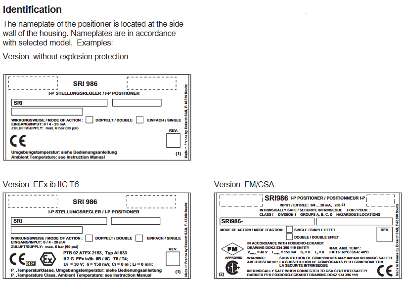
Environmental tolerance: Protection level IP66/IP67 (standard), IP68 (optional), temperature range -40~+85 ℃ (conventional), -55~+100 ℃ (high temperature option), certified by ATEX, IECEx, CSA and other explosion-proof certifications, can be used in Zone 1/2 (Class I hazardous areas) and corrosive environments (optional corrosion-resistant coating).
2. Key technological highlights
Non contact position detection: Abandoning traditional mechanical linkage detection, adopting Hall sensor+magnetic ring structure, no mechanical wear, with a lifespan of over 1 million cycles, reducing maintenance frequency.
Adaptive control algorithm: Built in "Auto Tune" function, automatically recognizes the characteristics of the actuator (such as stroke and response speed) after power on, optimizes PID control parameters, eliminates the need for manual debugging, and shortens installation time.
Modular design: divided into control unit (electronic module), pneumatic module (solenoid valve+air circuit) and connecting components, each module is independently disassembled and can be replaced separately in case of failure, reducing maintenance costs and downtime.
Hardware structure and technical specifications
1. Core components and functions
Component Category Key Component Function Description
Electronic control unit Hall position sensor, microprocessor, communication chip 1. Receive 4-20mA/HART/PROFIBUS PA input signals;
2. Check the actual position of the valve (resolution 0.01% of full range);
3. Execute PID control algorithm and output control signal to pneumatic module;
4. Store operational data and diagnostic information, and support remote communication.
Pneumatic module piezoelectric valve, pressure sensor, pneumatic block 1. Convert electronic signals into pneumatic signals (output pressure 0.2-1.0 MPa);
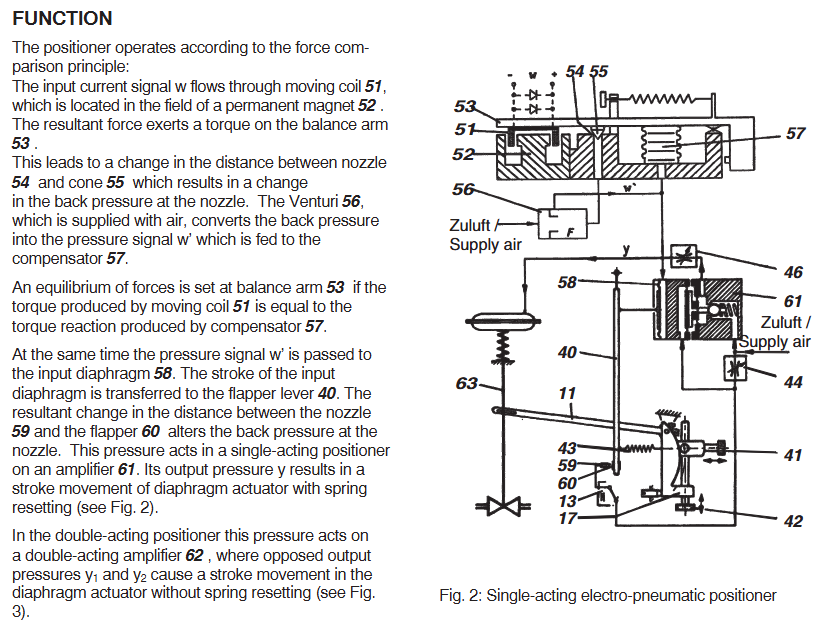
2. Single acting mechanism: controls the "on/off" side pressure (spring reset);
3. Double acting mechanism: independently controls the pressure on both sides of "on" and "off";
4. Built in pressure sensor, real-time monitoring of gas supply and output pressure.
Connecting and installing component brackets, connecting shafts, explosion-proof enclosures. 1. The bracket is compatible with straight stroke (ISO 5211 standard flange) and angular stroke (shaft diameter 10-30mm) actuators;
2. The connecting shaft supports ± 5 ° angle deviation compensation, simplifying installation alignment requirements;
3. The shell is made of aluminum alloy (conventional) or stainless steel (corrosion-resistant option), with an explosion-proof rating of Ex d IIC T6 (ATEX).
2. Key technical parameters
(1) Control performance
Parameter linear actuator angular actuator
Travel range 2-100 mm (standard), 100-300 mm (extended), 0-90 ° (standard), 0-180 °/0-360 ° (optional)
Adjustment accuracy ± 0.5% full range ± 0.5% full range
Response time ≤ 0.3 seconds (step signal 10% -90%) ≤ 0.5 seconds (step signal 10% -90%)
Dead zone ≤ 0.1% of full range (adjustable through software) ≤ 0.1% of full range
(2) Electrical and Pneumatic Parameters
Input signal:
Standard: 4-20 mA DC (load resistance 250-600 Ω)+HART 7.0;
Optional: PROFIBUS PA (IEC 61158-2, transmission rate 31.25 kbps).
Power requirements:
HART version: 12-30 V DC (typical power consumption 1.5 W);
PROFIBUS PA version: 9-32 V DC (compliant with IEC 61158-3 power supply standard).
Gas source requirements:
Pressure: 0.2-1.0 MPa (clean and dry compressed air, filtration accuracy ≤ 5 μ m, dew point 10 ℃ lower than ambient temperature);
Gas consumption: Double acting ≤ 0.3 Nm ³/h (steady state), single acting ≤ 0.2 Nm ³/h (steady state).
(3) Environment and Certification
Protection level: IP66 (dustproof and waterproof), IP67 (short-term immersion), IP68 (long-term immersion, optional);
Temperature range: -40~+85 ℃ (conventional), -55~+100 ℃ (high temperature option), -20~+60 ℃ (intrinsic safety version);
Explosion proof certification:
ATEX:Ex d IIC T6 Ga(Zone 1)、Ex nA IIC T6 Gc(Zone 2);
IECEx:Ex d IIC T6 Ga、Ex nA IIC T6 Gc;
CSA:Class I Div 1/2,Groups A-D,T6。
Operation and configuration process
1. Installation and initialization
(1) Mechanical installation
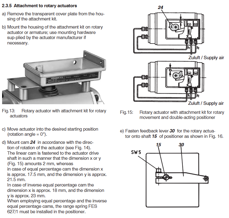
Bracket fixation: Select the corresponding bracket according to the type of actuator (straight stroke/angular stroke), and fix the locator with ISO 5211 flange (straight stroke) or shaft sleeve (angular stroke) to ensure that the connecting shaft is coaxial with the actuator shaft (deviation ≤ 5 °).
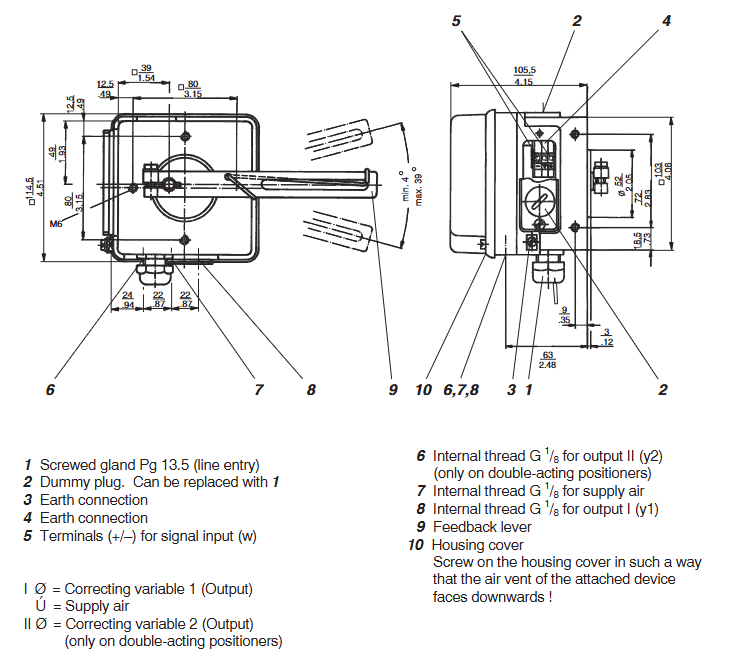
Air source connection: Connect clean compressed air to the "Supply" port (G1/4 thread) of the locator. Single acting mechanisms need to distinguish between "Output" (working side) and "Exhaust" (exhaust side), while double acting mechanisms need to distinguish between "Open" and "Close" ports.
Electrical wiring: The HART version is connected to a 12-30 V DC power supply and a 4-20 mA signal (two-wire system); The PROFIBUS PA version is connected to the bus power and signal lines (two-wire system), and the wiring terminals must meet explosion-proof sealing requirements (such as using explosion-proof gland heads).
(2) Auto Tune
Starting conditions: Ensure that the air source pressure is normal (0.2-1.0 MPa), the actuator is not stuck, and the locator is powered on (power light is always on).
Trigger self-tuning:
Local: Long press the "Auto Tune" button on the locator (3 seconds), the indicator light will flash (red), and enter self-tuning mode;
Remote: Send the "Auto Tune" command through a HART controller or control system.
Process and completion: The locator automatically drives the actuator to run throughout the entire stroke (2-3 times), records parameters such as stroke time and response characteristics, and optimizes PID parameters; After the self-tuning is completed, the indicator light turns green and stays on, and the system enters normal control mode.
2. Daily operations and diagnosis
(1) Local operation
Status indication: Judging the operating status through 3 LED lights——
Green constantly on: normal operation; Green flashing: self-tuning in progress;
Yellow constantly on: warning (such as low gas supply pressure, slight jamming); Yellow flashing: communication failure;
Red constantly on: serious malfunction (such as position sensor failure, actuator jamming); Red flashing: Over range alarm.
Manual adjustment: Long press the "Manual" button (3 seconds) to enter manual mode, adjust the valve opening through the "Up"/"Down" buttons, and release the button for 5 seconds to automatically return to automatic mode (to prevent misoperation).
(2) Remote diagnosis (HART/PROFIBUS PA)
The following key data and diagnostic information can be read through a handheld device or control system:
Operating data: actual valve opening (%), set value (%), supply pressure (MPa), output pressure (MPa), working temperature (℃);
Diagnostic information:
Mild malfunction: low gas supply pressure (<0.2 MPa), slow response of the actuator (jamming warning);
Severe faults: position sensor failure, piezoelectric valve failure, communication interruption;
Maintenance tips: valve action frequency (cumulative), last maintenance time, recommended maintenance cycle (such as checking the air circuit every 100000 actions).
Configuration options and ordering information
1. Core configuration options
Applicable scenarios for configuring category options
Communication protocol HART 7.0 (standard), PROFIBUS PA (optional) HART: for small and medium-sized systems, low cost; PROFIBUS PA: A large-scale bus system that requires multiple devices to be networked
Type of actuator: Linear, Rotary. Linear: Globe valve, gate valve; Angular stroke: butterfly valve, ball valve
Explosion proof rating Ex d IIC T6 (standard), Ex ia IIC T4 (intrinsic safety, optional) Ex d: Zone 1/2, suitable for high-risk areas; Ex ia:Zone 0/1, Suitable for extremely high-risk areas
Protection level IP66/IP67 (standard), IP68 (optional, water depth 1m/24h) IP68: humid environment (such as sewage treatment plant, outdoor during rainy season)
Materials and coatings: Aluminum alloy shell (conventional), stainless steel shell (optional), corrosion-resistant coating (PTFE, optional) Stainless steel+PTFE: corrosive environment (such as chemical acid/alkali gas)
2. Typical ordering models
Eckardt SRI986 model coding rule: SRI986- [Protocol] - [Type of actuator] - [Explosion proof level] - [Protection level], example as follows:
SRI986-H-LD-67: HART protocol, linear actuator, Ex d explosion-proof, IP67 protection;
SRI986-P-R-IA-68: PROFIBUS PA protocol, angular actuator, Ex ia intrinsic safety, IP68 protection;
SRI986-H-R-D-66: HART protocol, angular travel actuator, Ex d explosion-proof, IP66 protection (standard selection).
3. Common accessories
Installation accessories: Straight stroke bracket (SRI986Mount-L), angular stroke shaft sleeve (SRI986-Shift-R-20mm), explosion-proof gland head (M20, Ex d certified);
Maintenance accessories: piezoelectric valve spare parts (SRI986-Piezo-01), air filter (precision 5 μ m, with drainage), HART handheld controller (Rosemount 475);
Calibration tools: SRI986 Calibrator, pressure sensor calibration kit.
Application scenarios and core values
1. Typical application areas
Petrochemical industry: The feed control valve of the catalytic cracking unit and the reflux valve of the fractionation tower are controlled with high precision (± 0.5%) to ensure stable reaction temperature and pressure, avoiding the risk of overheating and overpressure;
Power industry: steam regulating valves for steam turbines in thermal power plants, outlet valves for cooling water pumps in nuclear power plants, suitable for high temperature environments (+85 ℃) and explosion-proof requirements, supporting PROFIBUS PA bus integration into DCS systems;
Water treatment: Water treatment plant dosing valve, sewage treatment plant aeration valve, IP68 protection suitable for humid environments, self-tuning function simplifies on-site debugging;
Pharmaceutical industry: mixing speed control valve for drug reaction kettle, flow valve for sterile filling line, stainless steel shell+PTFE coating to meet corrosion resistance and hygiene requirements, intelligent diagnosis to reduce unplanned downtime.
2. Core user value
Improve control accuracy: ± 0.5% adjustment accuracy reduces process fluctuations and enhances product qualification rate (such as chemical product purity and drug dosage accuracy);
Reduce maintenance costs: Non contact sensors have no wear and tear, modular design simplifies maintenance, predictive diagnosis provides early warning of faults, and reduces downtime (MTBF increases by more than 30%);
Simplified integration and debugging: compatible with mainstream communication protocols, self-tuning function does not require professional personnel, shortening project deployment cycle (reducing debugging time by 50%);
Adapt to harsh environments: wide temperature range, high protection, explosion-proof design, covering the vast majority of harsh working conditions in industrial sites, without the need for additional protective measures.
Maintenance and Precautions
Regular maintenance:
Every 3 months: Check the air source pressure and filter (clean impurities, drain water);
Every 6 months: calibrate the accuracy of the locator (perform "accuracy calibration" through a HART handheld device), and check the looseness of the connecting shaft;
Every year: Replace the air filter element and check the response performance of the piezoelectric valve (through diagnostic function).
Fault handling:
Low gas supply pressure: Check the pressure of the air compressor and clean the filter;
Position sensor malfunction: Check if the magnetic ring has come off and replace the sensor module;
Communication interruption: Check the wiring terminals to confirm that there is no short circuit or grounding on the HART/PROFIBUS PA bus.
Safety regulations:
Power off is required for maintenance in explosion-proof areas, explosion-proof tools should be used, and live disassembly and assembly are strictly prohibited;
The intrinsic safety version (Ex ia) must ensure that the bus power supply complies with the IEC 61158-3 standard to avoid excessive power supply;
Calibration and maintenance must be carried out by Eckardt certified engineers, using original spare parts to avoid affecting explosion-proof and precision performance.
- YOKOGAWA
- Reliance
- ADVANCED
- SEW
- ProSoft
- WATLOW
- Kongsberg
- FANUC
- VSD
- DCS
- PLC
- man-machine
- Covid-19
- Energy and Gender
- Energy Access
- Renewable Integration
- Energy Subsidies
- Energy and Water
- Net zero emission
- Energy Security
- Critical Minerals
- A-B
- petroleum
- Mine scale
- Sewage treatment
- cement
- architecture
- Industrial information
- New energy
- Automobile market
- electricity
- Construction site
- HIMA
- ABB
- Rockwell
- Schneider Modicon
- Siemens
- xYCOM
- Yaskawa
- Woodward
- BOSCH Rexroth
- MOOG
- General Electric
- American NI
- Rolls-Royce
- CTI
- Honeywell
- EMERSON
- MAN
- GE
- TRICONEX
- Control Wave
- ALSTOM
- AMAT
- STUDER
- KONGSBERG
- MOTOROLA
- DANAHER MOTION
- Bentley
- Galil
- EATON
- MOLEX
- Triconex
- DEIF
- B&W
- ZYGO
- Aerotech
- DANFOSS
- KOLLMORGEN
- Beijer
- Endress+Hauser
- schneider
- Foxboro
- KB
- REXROTH
- YAMAHA
- Johnson
- Westinghouse
- WAGO
- TOSHIBA
- TEKTRONIX
- BENDER
- BMCM
- SMC
- HITACHI
- HIRSCHMANN
- XP POWER
- Baldor
- Meggitt
- SHINKAWA
- Other Brands
- UniOP
- KUKA
- IBA
- Beckhoff
- ADLINK
-
ADLINK HPCI-14S12U - Industrial Control Backplane 12PCI Backplane PCI-14S Passive Backplane
-
ADLINK PCIe-GIE74C - image acquisition card 4-CH GigE Vision PoE+ Frame Grabber
-
ADLINK PCI-8164 - control card 4-Axis Advanced Motion Controller Board
-
ADLINK PCIe-U304 - 4 Port USB3 PCIe Frame Grabbers USB Screw Hole Card
-
ADLINK PCI-9112 - Multi-Function Data Acquisition Card DAQ Card
-
ADLINK PCI-7432 - 51-12013-0A50 4-CH Isolated Numérique I/O PCI Cartes Digital I/O Card
-
ADLINK PCA-6106P3-0C1 REV.C1 - backplane 6-Slot Passive Backplane Board
-
ADLINK PCI-7224 - 24-CH Opto-Isolated Digital I/O PCI Board
-
ADLINK CPCI-7433R(G) - Digital Input Board Rear I/O CompactPCI Card
-
ADLINK EBP-13E4 - 51-46703-0A30 Industrial PC Backplane Passive Backplane
-
ADLINK PCIE-HDV62 - Image acquisition card High Definition Video Frame Grabber
-
ADLINK EBP-13E4 - 51-46703-0A30 Industrial Backplane Board Passive Backplane
-
ADLINK 90111-B1 / CPCI-6770 - PCB CPU MODULE CompactPCI Single Board Computer
-
ADLINK PCI-7248 - DATA ACQUISITION PCI CARD 48-CH Parallel Digital I/O Board
-
ADLINK PCI-7230 - 51-12003-0a50 board PCI7230 32-CH Isolated Digital I/O Card
-
ADLINK PCI2A000CB - 51-20000-0B30 Multi-Function DAQ Card Baseboard
-
ADLINK PCI-8134-005 - 4-Axis Motion Controller Card
-
ADLINK PCI-7224 - 24-CH Opto-Isolated Digital I/O PCI Card
-
ADLINK PCI-7434 - 64-CH Isolated Digital Output Card
-
ADLINK PCI-8132 - motion control card 2-Axis Servo & Stepper Controller
-
ADLINK PCI-8134 - Motion Controller PCI Card 4-Axis Controller Board
-
ADLINK PCI-8164 - Motion Control Card 51-12406-0A40 4-Axis Controller
-
ADLINK 51-12001-0C20 - Circuit Board Data Acquisition Interface Module Hardware
-
ADLINK NuPR0-840 - industrial control motherboard Full-Size PICMG CPU Board
-
ADLINK PCI-7444 - 51-12023-0A10 card 128-CH Isolated Digital Output Board
-
ADLINK PCI-1612B - data acquisition card 4-Port RS-232/422/485 Serial Communication Card
-
ADLINK PCI-6208V 009 - 8/16-CH 16-Bit Analog Output Cards PCB-I-E-482=6BX3
-
ADLINK NUPRO-935A/LV - industrial control motherboard Full-Size PICMG SBC Board
-
ADLINK PCI-9114DG - Multi-Function DAQ Card Data Acquisition PCI Card
-
ADLINK ACL-7130 - Data acquisition card Isolated Digital I/O Board
-
ADLINK ABX-6300D-4E1-BP - board ABX6300D4E1BP Video Interface Expansion Card
-
ADLINK CPCI-6940 - CPCI-6940/D1539/M16-0(EA)-000E 6U CompactPCI Processor Board
-
ADLINK NuPRO-760 - industrial control motherboard Half-Size PICMG SBC CPU Board
-
ADLINK IMB-M42H (G)-0020 - industrial control motherboard LGA1155 Micro-ATX Mainboard
-
ADLINK RTV-24 / PCI-MP4S - 51-12519-1C30 4-Channel Real Time Video Capture Board
-
ADLINK PCI-8134 - 4-Axis Servo & Stepper Motion Controller Card
-
ADLINK MXC-6101D - V.PC000.002.ST.00 Box PC Configurable Embedded Computer
-
ADLINK PCI-8134A - 51-12421-0A10 Motion Control Card 4-Axis Controller Card
-
ADLINK DIN-100S / DIN-100SA1 - Technology SCSI-II TB 100-PIN Terminal Block Board
-
ADLINK DIN-812M001 / DIN812M001 - 51-14034-0A1 51140340A1 Terminal Module Breakout Interface
-
ADLINK PCI-8164 - Servo motion control 4-Axis Advanced Controller Card
-
ADLINK PCIe-GIE64 - Acquisition card GigE Vision PoE+ Frame Grabber
-
ADLINK M-302 - Industrial control motherboard ATX PC Board Mainboard
-
ADLINK PCI-8134 - Motion Controller PCI Card 4-Axis Controller Board
-
ADLINK PCI-RTV24 - Image capture card Analog Video Frame Grabber
-
ADLINK PCI-8102 - Motion control card 2-Axis Servo & Stepper Controller Board
-
ADLINK PCI-9112 REV.B1 - Card Multi-Function Data Acquisition Card
-
ADLINK HSI-DI32-M-N / HSL-TB32-M-DIN - Discrete I/O MODULE Distributed Automation Module System
-
ADLINK PCI-7296 - IO card REV.A3 96-CH Parallel Digital I/O Card
-
ADLINK DIN-814P-A4 / 814Y - terminal board Motion Control Interface Block
-
ADLINK DIN-814P-A4 - 51-14056-0A10 PCB-I-E-2736=ZA01 Screw Terminal Board Breakout
-
ADLINK M-322 - motherboard Industrial Control Computer Mainboard
-
ADLINK NUPRO-406 REV:B1 - industrial control motherboard Full-Size PICMG CPU Board
-
ADLINK AMP-204C - card DSP-Based 4-Axis Advanced Pulse-Train Controller
-
ADLINK HPCI14S REV.B1 - industrial computer baseboard 14-Slot Passive Backplane
-
ADLINK PCI-7250 - 8-CH Relay Output & 8-CH Isolated DI PCI Card
-
ADLINK EBP-13E2 - baseplate Passive Backplane Industrial Computer Chassis Board
-
ADLINK LPCI-3488A - PCI-GPIB card 51-12801-0A30 acquisition card IEEE-488 Interface Board
-
ADLINK PCI-6216V-GL - 51-12201-0C30 16-CH 16-Bit Voltage Analog Output Card
-
ADLINK ACL-8454 - 16-CH Isolated Digital I/O & 4-CH Counter Card
-
ADLINK HPCI-9S7U - backplane Passive Backplane Compatible with NuPRO-A301 852 841 842
-
ADLINK DAQ-2010-007 - Simultaneous-Sampling Multi-Function Data Acquisition Card
-
ADLINK MP-C154 - 51-64205-0A10 Motion Control Card 4-Axis Controller Board
-
ADLINK MXE-202/mSSD16B/WiFi-BT - Matrix Rugged I/O Platform Embedded Fanless Computer
-
ADLINK CM-920-R-17 - PC/104-Plus Single Board Computer Module Intel Celeron M
-
ADLINK PCI-7250 NSMP - 8-CH Relay Output & 8-CH Isolated DI Card
-
ADLINK PCI-8164 - 4-Axis Motion Controller PCI Card W/ Cable and Breakout Box
-
ADLINK EMX-100 - Ethernet-based 4-axis Motion Controllers Distributed Motion Module
-
ADLINK PCI-8134A - Press control card 4-Axis Motion Controller Board
-
ADLINK M-845EG REV:3.2 - industrial motherboard Pentium 4 Socket 478 Micro-ATX
-
ADLINK PCI-9114A Rev A2 DG - card High-Resolution Multi-Function Data Acquisition Board
-
ADLINK IEC-915GV - REV 1.1 Industrial motherboard Socket 478 CPU Board
-
ADLINK PCI-9111DG(G) - Data Acquisition Card Multi-Function DAQ Card
-
ADLINK HPCI-15S10 REV:B2 - Industrial computer base plate Passive Backplane Board
-
ADLINK NuPR0-840 / NuPR0-840DV - industrial control motherboard Full-size PICMG CPU Board
-
ADLINK RTV-24 / PCI-MP4S - 51-12519-1C30 4-Channel Real Time Video Capture Board
-
ADLINK NUPRO-780 - industrial control motherboard Pentium III Single Board Computer
-
ADLINK PCI-7296 - 0050 card 96-CH Opto-Isolated Parallel DIO Card Set
-
ADLINK NUPRO-780 - industrial control motherboard PICMG Full-Size SBC
-
ADLINK PCI-7248 - 51-12006-0A3 002 Pci 7248 48-CH Parallel Digital I/O Card
-
ADLINK cPCI-6626 - 6U CompactPCI 2.0 Blades i7-2710QE PCB-I-E-2570=9N41
-
ADLINK MXC-6322D(G) - Industrial Fanless Computer
-
ADLINK cPCI-8168-004 - CompactPci NulPC Motion Control Board 51-36402-0A3
-
ADLINK CPCI-7300[G] - COMPACTPCI Digital I/O Card Data Acquisition
-
ADLINK CPCI-6626/2710/M4G - COMPACTPCI COMPUTER BOARD
-
ADLINK cPCI-8168-009 - cPCI NulPC Motion Control Board
-
ADLINK cPCI-6626/2710/M4G - VME CPU Board Computer Board
-
ADLINK CPCI-R6200(G)-0040 - COMPACTPCI CONTROL BOARD
-
ADLINK CPCI-3840/PM18/M1G(G)-3650 - COMPACTPCI CPU Module Single Board Computer
-
ADLINK cPCI-7248 - 48-CH Opto-22 Compatible Digital I/O Module
-
ADLINK DLAP-211-JNX - NVIDIA Jetson Xavier NX Edge AI Inference Platform
-
ADLINK cPCI-3544 - Series 4-Port RS-422/485 Isolated Serial Communications Card
-
ADLINK CM1-86DX3 - PC/104 SBC Stanley Vortex86DX3 CPU 2GB Ram
-
ADLINK DLAP-211-JNX - NVIDIA Jetson Xavier NX Edge AI Inference Platform
-
ADLINK cPCI-3544 - Series 4-Port RS-422/485 Isolated Serial Communications Card
-
ADLINK CM1-86DX3 - PC/104 SBC Stanley Vortex86DX3 CPU 2GB Ram
-
ADLINK PCI-7433 - switch value acquisition card Isolated Digital Input Card
-
ADLINK PCI-9112 - 51-12252-0D20 Multi-Function Data Acquisition Card
-
ADLINK NUPRO-A301 REV:1.4 - industrial control motherboard PICMG Full-Size SBC
-
ADLINK 51-18502-0A10 - Frame Grabber Image Acquisition Interface Card
-
ADLINK PCI-7296 - 51-12009-0A50 PCB-I-E-925=6DX1 96-CH Parallel Digital I/O Board
-
ADLINK PCI-8132 GP A2 - Motion Control Card 2-Axis Servo & Stepper Controller
-
ADLINK PCI-7442 - switch quantity card data acquisition card 64-CH Isolated Card
-
ADLINK HPX-13S4 - baseboard PICMG 1.3 Passive Backplane Chassis Baseplate
-
ADLINK NuPRO-590 / NTC-567-ZM-F36 - Single Board Computer PCB-I-E-1853=9L21 Half-Size SBC
-
ADLINK PCIe-8332 - 16-axis plate Motion Control Hardware Card
-
ADLINK NuPRO-775 REV.B1 - motherboard Pentium 4 Full-Size PICMG SBC
-
ADLINK PXI-3920 - Embedded Controller 3U PXI cPCI System Intelligence Board
-
ADLINK PCI-8134 - driver card motion control card 4-Axis Controller Board
-
ADLINK HSL-DI32-M-N-011 / HSL-TB32-M-DIN - Digital Input & Base Module PLC Distributed I/O System
-
ADLINK PCI-6216V-206 / PCI-208V 009 - 16 CH 16bit analog output card
-
ADLINK NuPro-E330 - 51-41805-0A20 PCB Single Board Computer Host Board
-
ADLINK PCI-1622C - Card 8-Port RS-232/422/485 PCI Serial Communication Board
-
ADLINK PCIe-7432 - 51-18402-0A10 Carte PCIe Avec Plage D'Entrée Élevée Isolated DIO Card
-
ADLINK PCI-7250 - PCI Acquisition Card 8-CH Relay Output Isolated DI Card
-
ADLINK PCI-7230 - 32-CH Isolated Digital I/O Card
-
ADLINK PCI-8164 - PCB 4-Axis Motion Controller Card
-
ADLINK PCI-7854 - Collection card High-Speed Link Distributed Motion Controller
-
ADLINK NuPRO-935A/LV - industrial control computer motherboard Full-Size PICMG SBC
-
ADLINK IMB-M40H - motherboard IH61-AA4 1155 LGA1155 Micro-ATX Mainboard
-
ADLINK PCI-7248 - Linhua 51-12006-0A40 48-CH Parallel Digital I/O Card
-
ADLINK HPCI-14S12U - Linhua industrial computer baseboard Passive Backplane
-
ADLINK PCI-8132 Rev.A2 - 2-Axis Servo & Stepper Motion Controller Card
-
ADLINK ACL-8111 - ISA card Multi-Function DAQ Card
-
ADLINK ACL-8111 - ISA card Multi-Function Data Acquisition Board
-
ADLINK PCI-7200 REV.A3 - Digital I/O card 12MB/s High-Speed Parallel Digital I/O
-
ADLINK PCI-7296 REV.A3 - 96-CH High-Density Opto-Isolated DIO Card
-
ADLINK PCI-7434 - 64-CH Isolated Digital Output Card

K-JIANG

Add: Jimei North Road, Jimei District, Xiamen, Fujian, China
Tell:+86-15305925923