
K-WANG


Rockwell Automation SmartGuard 600 Controller
Controller positioning: Programmable Electronic Safety System (PES), supporting 16 digital inputs, 8 digital outputs, 4 test pulse outputs, 1752-L24BBBE with additional support for EtherNet/IP communication;
Safety certification: meets high safety level requirements - IEC 61508 SIL 3, ISO 13849-1 PL (e), EN 954-1 CAT 4, suitable for hazardous environments (North American Class I Div 2 Groups A-D).
Rockwell Automation SmartGuard 600 Controller
Basic and Controller Core Positioning
1. Basic information
Document purpose: To guide the installation, parameter configuration, wiring, and status interpretation of safety controllers, suitable for deployment in industrial safety scenarios such as emergency stop and safety door monitoring;
Controller positioning: Programmable Electronic Safety System (PES), supporting 16 digital inputs, 8 digital outputs, 4 test pulse outputs, 1752-L24BBBE with additional support for EtherNet/IP communication;
Safety certification: meets high safety level requirements - IEC 61508 SIL 3, ISO 13849-1 PL (e), EN 954-1 CAT 4, suitable for hazardous environments (North American Class I Div 2 Groups A-D).
2. Comparison of Model Differences
Model Core Differences Communication Interface Applicable Scenarios
1752-L24BBB Basic Security Control USB+DeviceNet Security Scenarios without Ethernet Requirements (such as Single Device Security Monitoring)
1752-L24BBBE adds Ethernet functionality USB+DeviceNet+EtherNet/IP for distributed security systems that require remote Ethernet monitoring (such as production line level security linkage)
Key configurations before installation (mandatory steps)
1. Safety prerequisite requirements
Precautions for hazardous environments:
It is strictly prohibited to plug and unplug wires with electricity (which may cause arcing and explosion). Power must be cut off or the environment must be confirmed to be in a non hazardous area first;
Prohibition of replacing non original components (which may damage Class I Div 2 compatibility);
Battery replacement is only allowed in non hazardous areas.
Electrostatic protection: Before operation, touch a grounded object to discharge electricity, wear an anti-static wristband, prohibit touching circuit board pins, and store in anti-static packaging when idle.
2. Core parameter configuration (power-off operation)
(1) DeviceNet node address setting
Configuration method: Set through the two rotary switches (ten position+one position) on the front of the controller, with a range of 00~63 (default 63);
Software configuration compatibility: If setting the address through RSNetWorx for DeviceNet software, the rotary switch needs to be turned to 64~99;
Key reminder: Avoid duplicate node addresses, otherwise communication errors may be triggered.
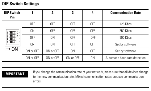
(2) DeviceNet communication rate setting
Default speed: 125 kbps, supports three speeds of 125/250/500 kbps, configured through a 4-digit DIP switch:
DIP switch (1-4) communication rate description
OFF-OFF-OFF-OFF 125 kbps default value
ON-OFF-OFF-OFF 250 kbps medium range networking
OFF-ON-OFF-OFF 500 kbps short distance high throughput scenario
The software configuration of ON-ON-OFF-OFF needs to be set through RSNetWorx
Speed and distance matching: The higher the speed, the shorter the supported cable length (such as 75m for flat cables and 100m for thick cables at 500 kbps), which needs to be selected according to the network size.
(3) EtherNet/IP IP Address Setting (1752-L24BBBE only)
Default mode: BOOTP enabled, IP needs to be allocated through BOOTP server (recommended Rockwell free tool, download link: http://www.ab.com/networks/bootp.html );
Configuration steps:
Run the BOOTP tool and double-click on the device MAC address;
Enter the target IP in the pop-up window and click confirm;
The IP address of the controller can be viewed on the display screen through the front "IP Address Display Switch" (long press for more than 1 second), and error code "n4" indicates abnormal Ethernet configuration.
Controller installation and wiring specifications
1. Physical installation (DIN rail fixation)
Installation requirements:
Only supports EN 50022 standard DIN rails (35x7.5mm or 35x15mm), horizontal installation (vertical installation may affect heat dissipation);
Heat dissipation gap: at least 50mm (2.0in) up and down, and at least 5mm (0.20in) left and right, avoiding installation above heating equipment;
Installation steps:
Hang the top card slot of the controller on the DIN rail;
Press the bottom of the controller and tighten the bottom buckle (1752-L24BBB single buckle, 1752-L24BBBE double buckle);
Install end plates at both ends of the guide rail to ensure stability.
Grounding requirements: Chassis grounding is achieved through DIN rails, which require the use of galvanized yellow chromium steel rails (aluminum/plastic rails may cause poor grounding), and the rails should be fixed every 200mm (7.8in).
2. Power wiring (safety power supply is the core)
Power specifications:
External power supply: 24V DC (allowable range 20.4~26.4V DC), output holding time ≥ 20ms;
Safety compliance: Must meet SELV/PELV (CE LVD), Class 2 (UL 508), and recommend Rockwell 1606 series power supplies (such as 1606-XLP30E, 1606-XL60DR);
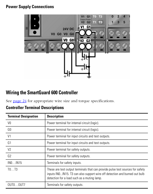
Terminal wiring:
The controller includes 3 sets of V/G terminals (V0/G0: internal logic power supply; V1/G1: Input and test output power supply; V2/G2: Safe output power supply);
The V0/G0 two sets of terminals are internally connected, only one set needs to be connected, and the other set can be used to distribute power to other devices.
3. I/O and communication wiring (according to scene specifications)
(1) Input wiring (compatible with two types of devices)
Mechanical contact equipment (such as emergency stop button): It is necessary to simultaneously connect the "safety input terminal (INx)" and the "test output terminal (Tx)" to achieve CAT 4 level, with a wiring length of ≤ 30m;
PNP semiconductor devices (such as safety light curtains): only connected to the safety input terminal (INx), no need to test the output, typical current is 4.5mA.
(2) Output wiring (distinguishing between safety and test outputs)
Safe output (OUT0~OUT7): Maximum load 0.5A, wiring beyond the rated value is strictly prohibited, and it is not allowed to be used as a test output;
Test output (T0~T3): Only used for input circuit testing, T3 additionally supports wire breakage/bulb burnout detection and cannot be connected to safety loads.
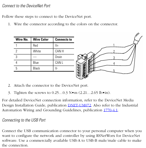
(3) Communication wiring
DeviceNet wiring: 5-wire connector, corresponding by color (red V+, white CAN H, blue CAN L, black V -, empty Drain), screw torque 0.25~0.3N · m;
USB wiring: only for temporary configuration (non permanent connection), cable length ≤ 3m, USB-A to USB-B male to male cable is required;
EtherNet/IP wiring (only 1752-L24BBBE): RJ45 interface, CAT5e/CAT5 cable, length ≤ 100m, pins 1 (TD+), 2 (TD -), 3 (RD+), 6 (RD -).
Interpretation of Status Indicators and Troubleshooting
1. Meaning of core indicator lights (sorted by classification)
(1) Module status (MS) indicator light
Suggestions for handling the meaning of indicator light status
Turn off the power supply and check the power wiring. Restart the power supply
Green constantly on, normal operation (Run mode), no operation required
Green flashing standby mode (Idle) to confirm if the configuration is complete
Red flashing can restore faults (such as configuration errors). Check the switch configuration and reset the configuration data
The red light is constantly on and cannot be restored due to a fault (such as hardware damage). Check the wiring, eliminate interference, and contact after-sales service
Red green alternating flashing self-test/configuration download waiting for completion. If it continues to flash, it needs to be reconfigured
(2) Network status indicator light
DeviceNet (NS D): Green constant light=online and connected, red constant light=MAC address conflict/bus disconnection, address and cable need to be checked;
EtherNet/IP (NS E, BE only): Green constant light indicates Ethernet connection, red constant light indicates IP address conflict, IP needs to be reassigned.
(3) I/O status indicator light
Yellow constant light=signal normal, red constant light/flashing=circuit fault (such as disconnection, short circuit, overcurrent), wiring and load need to be checked.
2. Interpretation of Display Screen Information
Normal state: Display node address (00~63), standalone mode displays "nd";
Fault status: alternately display error codes and node addresses (such as F0=MAC conflict, F1=bus disconnection);
Special function: Press the "Service Switch" to display the security configuration signature (verifying that the program has not been tampered with), press the "IP Display Switch" to display the Ethernet IP.
Key specifications and supporting resources
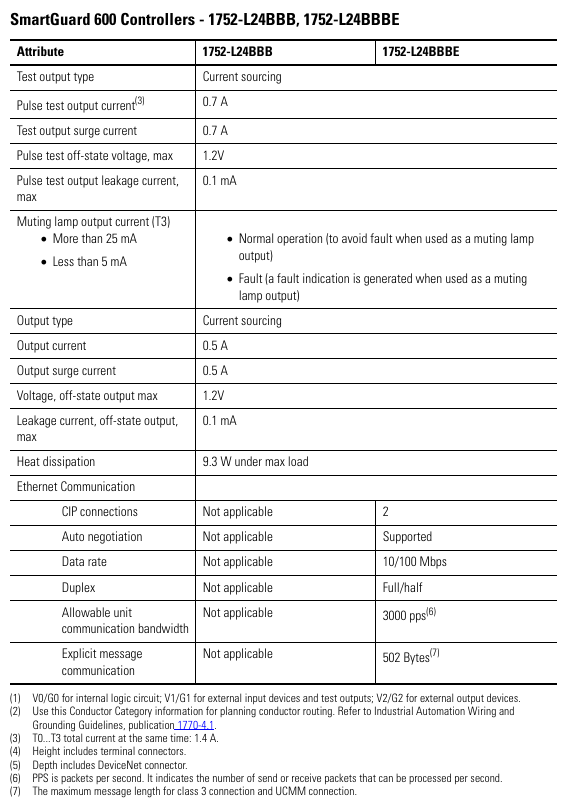
1. Core technical parameters
Specification item 1752-L24BBB 1752-L24BBBE
Size (HxWxD) 99x99.4x131.4mm 99x113x131.4mm
Weight 460g 575g
Working temperature -10~55 ℃ (14~131 ℉) same as left
Protection level IP20, same as left
Input current 4.5mA (per channel) same as left
Output current 0.5A (per channel, maximum) same as left
Ethernet speed -10/100Mbps (full/half duplex)
2. Supporting resources
Key manuals:
SmartGuard 600 User Manual (1752-UM001): Controller Configuration and Troubleshooting;
SmartGuard 600 Safety Reference Manual (1752-RM001): Safety Concepts and PFD/PFH Calculations;
tool
Configuration software: RSNetWorx for DeviceNet (DeviceNet configuration), BOOTP tool (IP configuration);
Core safety operation reminder
Prohibited behavior:
Test outputs cannot be used as safety outputs, and safety signals cannot be transmitted using DeviceNet standard I/O data;
It is prohibited to disassemble/modify the controller (which may damage safety functions);
Do not allow the 24V DC line to accidentally touch the output terminal to avoid starting the load.
Wiring specifications:
Input/output cables should be arranged separately from high-voltage/high current cables to avoid interference;
Stranded wires require the installation of DIN 46228-4 standard insulated Ferrules (non-standard Ferrules may not match the terminals).

- YOKOGAWA
- Reliance
- ADVANCED
- SEW
- ProSoft
- WATLOW
- Kongsberg
- FANUC
- VSD
- DCS
- PLC
- man-machine
- Covid-19
- Energy and Gender
- Energy Access
- Renewable Integration
- Energy Subsidies
- Energy and Water
- Net zero emission
- Energy Security
- Critical Minerals
- A-B
- petroleum
- Mine scale
- Sewage treatment
- cement
- architecture
- Industrial information
- New energy
- Automobile market
- electricity
- Construction site
- HIMA
- ABB
- Rockwell
- Schneider Modicon
- Siemens
- xYCOM
- Yaskawa
- Woodward
- BOSCH Rexroth
- MOOG
- General Electric
- American NI
- Rolls-Royce
- CTI
- Honeywell
- EMERSON
- MAN
- GE
- TRICONEX
- Control Wave
- ALSTOM
- AMAT
- STUDER
- KONGSBERG
- MOTOROLA
- DANAHER MOTION
- Bentley
- Galil
- EATON
- MOLEX
- Triconex
- DEIF
- B&W
- ZYGO
- Aerotech
- DANFOSS
- KOLLMORGEN
- Beijer
- Endress+Hauser
- schneider
- Foxboro
- KB
- REXROTH
- YAMAHA
- Johnson
- Westinghouse
- WAGO
- TOSHIBA
- TEKTRONIX
- BENDER
- BMCM
- SMC
- HITACHI
- HIRSCHMANN
- XP POWER
- Baldor
- Meggitt
- SHINKAWA
- Other Brands
- UniOP
- KUKA
- IBA
- Beckhoff
- ADLINK
-
ADLINK HPCI-14S12U - Industrial Control Backplane 12PCI Backplane PCI-14S Passive Backplane
-
ADLINK PCIe-GIE74C - image acquisition card 4-CH GigE Vision PoE+ Frame Grabber
-
ADLINK PCI-8164 - control card 4-Axis Advanced Motion Controller Board
-
ADLINK PCIe-U304 - 4 Port USB3 PCIe Frame Grabbers USB Screw Hole Card
-
ADLINK PCI-9112 - Multi-Function Data Acquisition Card DAQ Card
-
ADLINK PCI-7432 - 51-12013-0A50 4-CH Isolated Numérique I/O PCI Cartes Digital I/O Card
-
ADLINK PCA-6106P3-0C1 REV.C1 - backplane 6-Slot Passive Backplane Board
-
ADLINK PCI-7224 - 24-CH Opto-Isolated Digital I/O PCI Board
-
ADLINK CPCI-7433R(G) - Digital Input Board Rear I/O CompactPCI Card
-
ADLINK EBP-13E4 - 51-46703-0A30 Industrial PC Backplane Passive Backplane
-
ADLINK PCIE-HDV62 - Image acquisition card High Definition Video Frame Grabber
-
ADLINK EBP-13E4 - 51-46703-0A30 Industrial Backplane Board Passive Backplane
-
ADLINK 90111-B1 / CPCI-6770 - PCB CPU MODULE CompactPCI Single Board Computer
-
ADLINK PCI-7248 - DATA ACQUISITION PCI CARD 48-CH Parallel Digital I/O Board
-
ADLINK PCI-7230 - 51-12003-0a50 board PCI7230 32-CH Isolated Digital I/O Card
-
ADLINK PCI2A000CB - 51-20000-0B30 Multi-Function DAQ Card Baseboard
-
ADLINK PCI-8134-005 - 4-Axis Motion Controller Card
-
ADLINK PCI-7224 - 24-CH Opto-Isolated Digital I/O PCI Card
-
ADLINK PCI-7434 - 64-CH Isolated Digital Output Card
-
ADLINK PCI-8132 - motion control card 2-Axis Servo & Stepper Controller
-
ADLINK PCI-8134 - Motion Controller PCI Card 4-Axis Controller Board
-
ADLINK PCI-8164 - Motion Control Card 51-12406-0A40 4-Axis Controller
-
ADLINK 51-12001-0C20 - Circuit Board Data Acquisition Interface Module Hardware
-
ADLINK NuPR0-840 - industrial control motherboard Full-Size PICMG CPU Board
-
ADLINK PCI-7444 - 51-12023-0A10 card 128-CH Isolated Digital Output Board
-
ADLINK PCI-1612B - data acquisition card 4-Port RS-232/422/485 Serial Communication Card
-
ADLINK PCI-6208V 009 - 8/16-CH 16-Bit Analog Output Cards PCB-I-E-482=6BX3
-
ADLINK NUPRO-935A/LV - industrial control motherboard Full-Size PICMG SBC Board
-
ADLINK PCI-9114DG - Multi-Function DAQ Card Data Acquisition PCI Card
-
ADLINK ACL-7130 - Data acquisition card Isolated Digital I/O Board
-
ADLINK ABX-6300D-4E1-BP - board ABX6300D4E1BP Video Interface Expansion Card
-
ADLINK CPCI-6940 - CPCI-6940/D1539/M16-0(EA)-000E 6U CompactPCI Processor Board
-
ADLINK NuPRO-760 - industrial control motherboard Half-Size PICMG SBC CPU Board
-
ADLINK IMB-M42H (G)-0020 - industrial control motherboard LGA1155 Micro-ATX Mainboard
-
ADLINK RTV-24 / PCI-MP4S - 51-12519-1C30 4-Channel Real Time Video Capture Board
-
ADLINK PCI-8134 - 4-Axis Servo & Stepper Motion Controller Card
-
ADLINK MXC-6101D - V.PC000.002.ST.00 Box PC Configurable Embedded Computer
-
ADLINK PCI-8134A - 51-12421-0A10 Motion Control Card 4-Axis Controller Card
-
ADLINK DIN-100S / DIN-100SA1 - Technology SCSI-II TB 100-PIN Terminal Block Board
-
ADLINK DIN-812M001 / DIN812M001 - 51-14034-0A1 51140340A1 Terminal Module Breakout Interface
-
ADLINK PCI-8164 - Servo motion control 4-Axis Advanced Controller Card
-
ADLINK PCIe-GIE64 - Acquisition card GigE Vision PoE+ Frame Grabber
-
ADLINK M-302 - Industrial control motherboard ATX PC Board Mainboard
-
ADLINK PCI-8134 - Motion Controller PCI Card 4-Axis Controller Board
-
ADLINK PCI-RTV24 - Image capture card Analog Video Frame Grabber
-
ADLINK PCI-8102 - Motion control card 2-Axis Servo & Stepper Controller Board
-
ADLINK PCI-9112 REV.B1 - Card Multi-Function Data Acquisition Card
-
ADLINK HSI-DI32-M-N / HSL-TB32-M-DIN - Discrete I/O MODULE Distributed Automation Module System
-
ADLINK PCI-7296 - IO card REV.A3 96-CH Parallel Digital I/O Card
-
ADLINK DIN-814P-A4 / 814Y - terminal board Motion Control Interface Block
-
ADLINK DIN-814P-A4 - 51-14056-0A10 PCB-I-E-2736=ZA01 Screw Terminal Board Breakout
-
ADLINK M-322 - motherboard Industrial Control Computer Mainboard
-
ADLINK NUPRO-406 REV:B1 - industrial control motherboard Full-Size PICMG CPU Board
-
ADLINK AMP-204C - card DSP-Based 4-Axis Advanced Pulse-Train Controller
-
ADLINK HPCI14S REV.B1 - industrial computer baseboard 14-Slot Passive Backplane
-
ADLINK PCI-7250 - 8-CH Relay Output & 8-CH Isolated DI PCI Card
-
ADLINK EBP-13E2 - baseplate Passive Backplane Industrial Computer Chassis Board
-
ADLINK LPCI-3488A - PCI-GPIB card 51-12801-0A30 acquisition card IEEE-488 Interface Board
-
ADLINK PCI-6216V-GL - 51-12201-0C30 16-CH 16-Bit Voltage Analog Output Card
-
ADLINK ACL-8454 - 16-CH Isolated Digital I/O & 4-CH Counter Card
-
ADLINK HPCI-9S7U - backplane Passive Backplane Compatible with NuPRO-A301 852 841 842
-
ADLINK DAQ-2010-007 - Simultaneous-Sampling Multi-Function Data Acquisition Card
-
ADLINK MP-C154 - 51-64205-0A10 Motion Control Card 4-Axis Controller Board
-
ADLINK MXE-202/mSSD16B/WiFi-BT - Matrix Rugged I/O Platform Embedded Fanless Computer
-
ADLINK CM-920-R-17 - PC/104-Plus Single Board Computer Module Intel Celeron M
-
ADLINK PCI-7250 NSMP - 8-CH Relay Output & 8-CH Isolated DI Card
-
ADLINK PCI-8164 - 4-Axis Motion Controller PCI Card W/ Cable and Breakout Box
-
ADLINK EMX-100 - Ethernet-based 4-axis Motion Controllers Distributed Motion Module
-
ADLINK PCI-8134A - Press control card 4-Axis Motion Controller Board
-
ADLINK M-845EG REV:3.2 - industrial motherboard Pentium 4 Socket 478 Micro-ATX
-
ADLINK PCI-9114A Rev A2 DG - card High-Resolution Multi-Function Data Acquisition Board
-
ADLINK IEC-915GV - REV 1.1 Industrial motherboard Socket 478 CPU Board
-
ADLINK PCI-9111DG(G) - Data Acquisition Card Multi-Function DAQ Card
-
ADLINK HPCI-15S10 REV:B2 - Industrial computer base plate Passive Backplane Board
-
ADLINK NuPR0-840 / NuPR0-840DV - industrial control motherboard Full-size PICMG CPU Board
-
ADLINK RTV-24 / PCI-MP4S - 51-12519-1C30 4-Channel Real Time Video Capture Board
-
ADLINK NUPRO-780 - industrial control motherboard Pentium III Single Board Computer
-
ADLINK PCI-7296 - 0050 card 96-CH Opto-Isolated Parallel DIO Card Set
-
ADLINK NUPRO-780 - industrial control motherboard PICMG Full-Size SBC
-
ADLINK PCI-7248 - 51-12006-0A3 002 Pci 7248 48-CH Parallel Digital I/O Card
-
ADLINK cPCI-6626 - 6U CompactPCI 2.0 Blades i7-2710QE PCB-I-E-2570=9N41
-
ADLINK MXC-6322D(G) - Industrial Fanless Computer
-
ADLINK cPCI-8168-004 - CompactPci NulPC Motion Control Board 51-36402-0A3
-
ADLINK CPCI-7300[G] - COMPACTPCI Digital I/O Card Data Acquisition
-
ADLINK CPCI-6626/2710/M4G - COMPACTPCI COMPUTER BOARD
-
ADLINK cPCI-8168-009 - cPCI NulPC Motion Control Board
-
ADLINK cPCI-6626/2710/M4G - VME CPU Board Computer Board
-
ADLINK CPCI-R6200(G)-0040 - COMPACTPCI CONTROL BOARD
-
ADLINK CPCI-3840/PM18/M1G(G)-3650 - COMPACTPCI CPU Module Single Board Computer
-
ADLINK cPCI-7248 - 48-CH Opto-22 Compatible Digital I/O Module
-
ADLINK DLAP-211-JNX - NVIDIA Jetson Xavier NX Edge AI Inference Platform
-
ADLINK cPCI-3544 - Series 4-Port RS-422/485 Isolated Serial Communications Card
-
ADLINK CM1-86DX3 - PC/104 SBC Stanley Vortex86DX3 CPU 2GB Ram
-
ADLINK DLAP-211-JNX - NVIDIA Jetson Xavier NX Edge AI Inference Platform
-
ADLINK cPCI-3544 - Series 4-Port RS-422/485 Isolated Serial Communications Card
-
ADLINK CM1-86DX3 - PC/104 SBC Stanley Vortex86DX3 CPU 2GB Ram
-
ADLINK PCI-7433 - switch value acquisition card Isolated Digital Input Card
-
ADLINK PCI-9112 - 51-12252-0D20 Multi-Function Data Acquisition Card
-
ADLINK NUPRO-A301 REV:1.4 - industrial control motherboard PICMG Full-Size SBC
-
ADLINK 51-18502-0A10 - Frame Grabber Image Acquisition Interface Card
-
ADLINK PCI-7296 - 51-12009-0A50 PCB-I-E-925=6DX1 96-CH Parallel Digital I/O Board
-
ADLINK PCI-8132 GP A2 - Motion Control Card 2-Axis Servo & Stepper Controller
-
ADLINK PCI-7442 - switch quantity card data acquisition card 64-CH Isolated Card
-
ADLINK HPX-13S4 - baseboard PICMG 1.3 Passive Backplane Chassis Baseplate
-
ADLINK NuPRO-590 / NTC-567-ZM-F36 - Single Board Computer PCB-I-E-1853=9L21 Half-Size SBC
-
ADLINK PCIe-8332 - 16-axis plate Motion Control Hardware Card
-
ADLINK NuPRO-775 REV.B1 - motherboard Pentium 4 Full-Size PICMG SBC
-
ADLINK PXI-3920 - Embedded Controller 3U PXI cPCI System Intelligence Board
-
ADLINK PCI-8134 - driver card motion control card 4-Axis Controller Board
-
ADLINK HSL-DI32-M-N-011 / HSL-TB32-M-DIN - Digital Input & Base Module PLC Distributed I/O System
-
ADLINK PCI-6216V-206 / PCI-208V 009 - 16 CH 16bit analog output card
-
ADLINK NuPro-E330 - 51-41805-0A20 PCB Single Board Computer Host Board
-
ADLINK PCI-1622C - Card 8-Port RS-232/422/485 PCI Serial Communication Board
-
ADLINK PCIe-7432 - 51-18402-0A10 Carte PCIe Avec Plage D'Entrée Élevée Isolated DIO Card
-
ADLINK PCI-7250 - PCI Acquisition Card 8-CH Relay Output Isolated DI Card
-
ADLINK PCI-7230 - 32-CH Isolated Digital I/O Card
-
ADLINK PCI-8164 - PCB 4-Axis Motion Controller Card
-
ADLINK PCI-7854 - Collection card High-Speed Link Distributed Motion Controller
-
ADLINK NuPRO-935A/LV - industrial control computer motherboard Full-Size PICMG SBC
-
ADLINK IMB-M40H - motherboard IH61-AA4 1155 LGA1155 Micro-ATX Mainboard
-
ADLINK PCI-7248 - Linhua 51-12006-0A40 48-CH Parallel Digital I/O Card
-
ADLINK HPCI-14S12U - Linhua industrial computer baseboard Passive Backplane
-
ADLINK PCI-8132 Rev.A2 - 2-Axis Servo & Stepper Motion Controller Card
-
ADLINK ACL-8111 - ISA card Multi-Function DAQ Card
-
ADLINK ACL-8111 - ISA card Multi-Function Data Acquisition Board
-
ADLINK PCI-7200 REV.A3 - Digital I/O card 12MB/s High-Speed Parallel Digital I/O
-
ADLINK PCI-7296 REV.A3 - 96-CH High-Density Opto-Isolated DIO Card
-
ADLINK PCI-7434 - 64-CH Isolated Digital Output Card

K-JIANG

Add: Jimei North Road, Jimei District, Xiamen, Fujian, China
Tell:+86-15305925923